Crestron 3-Series Quick Start
Media presentation controller
Hide thumbs
Also See for 3-Series:
- Operation manual (62 pages) ,
- Supplemental manual (20 pages) ,
- Quick start manual (8 pages)
Advertisement
Quick Links
MPC3-101/MPC3-102
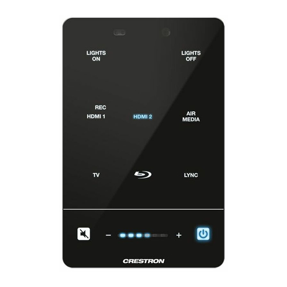
3-Series® Media Presentation Controller 101/102
The Crestron® MPC3-101 and MPC3-102 are wall-mounted, PoE (Power over Ethernet) powered
3-Series® automated processors and control panels all in one. The MPC3-101 and MPC3-102
offer fully-programmable functionality, support configuration and management via web or
cloud-based interfaces, and integrate with Crestron Fusion® software as part of a complete
managed enterprise solution.
NOTE:
For simplicity within this guide, the term "MPC3 device" is used to refer to both the
MPC3-101 and MPC3-102 unless otherwise noted.
Check the Box
Item
MPC3-101 or MPC3-102
Bit, Torx®, T8, Security (P/N 2025915)
Cable, Grounding (P/N 4509212)
Icon Chips, 30 Piece Set (P/N 4526558)
Screw, 4-40 x 3/16 in., Flat Head, Torx®, Black (P/N 2032041)
Screw, 4-40 x 1/4 in., Undercut Head, Phillips, Black (P/N 2007152)
Screw, 6-32 x 1/4 in., Pan Head, SEMS (P/N 2007214)
Screw, 6-32 x 1 in., Undercut Head, Phillips (P/N 2051398)
MPC3-101 Only
Connector, 2-Pin (P/N 2003574)
Connector, 3-Pin (P/N 2003575)
MPC3-102 Only
Connector, 3-Pin (P/N 2003575)
Connector, 5-Pin (P/N 2003577)
Attach the Mounting Plate
The MPC3 device is designed to install into a 1-gang U.S. electrical box.
NOTE:
The MPC3-101/102/201-RMB retrofit mounting bracket is also available to allow
installation over a 2-gang U.S. electrical box for replacing an older MPC-M5 series controller. For
more information, refer to the MPC3-101/102/201-RMB Quick Start (Doc. 8316) at
www.crestron.com/manuals.
Use the two included 6-32 x 1 in. screws to attach the MPC3 device mounting plate to the
electrical box.
1-gang U.S.
electrical box
Screws (2):
Mounting
6-32 x 1 in.
plate
Connect the Device
To comply with the European Directive (CE), Crestron recommends using shielded CAT5e cable
as a minimum for PoE power.
Route all necessary cables through the rear of the electrical box, and then make connections to
the MPC3 device as shown in the following illustrations.
NOTE:
Make all cable connections prior to attaching the MPC3 device assembly to the electrical
box.
MPC3-101 Cable Connections (Top and Rear Views)
LAN PoE:
Attach grounding cable
100BASE-TX
here (with 6-32 x 1/4 in.
Qty
Ethernet to LAN
SEMS screw)
1
1
1
1
1
5
1
2
1
1
3
MPC3-102 Cable Connections (Top and Rear Views)
1
LAN PoE:
Attach grounding cable
100BASE-TX
here (with 6-32 x 1/4 in.
Ethernet to LAN
SEMS screw)
Observe the following when making connections to the MPC3 device:
•
Use Crestron power supplies for Crestron equipment.
•
A single Ethernet cable provides power and data to the MPC3 device. A Crestron
PoE power supply, such as the PWE-4803RU, or a PoE-capable network switch is
recommended (both sold separately).
•
Ensure that the MPC3 device is grounded properly. Insert the 6-32 x 1/4 in. SEMS screw
through the terminal ring end of the included grounded cable, and then attach the screw
to the hole in the rear of the assembly as shown in the illustration above. Then, attach the
other end of the cable to a known earth ground (such as building steel).
•
Apply power to the MPC3 device after all connections have been made.
Install the Device
To install the MPC3 device:
1.
Once all cable connections have been made, use four of the included 4-40 x 1/4 in. Phillips
screws to attach the MPC3 device assembly to the mounting plate.
IR:
To IRP2 emitter or serial devices
NET:
To any Cresnet® network device
Screws (4):
4-40 x 1/4 in.
2.
Punch out the desired icon chips from the icon packaging sheet.
3.
Insert the chips, bottom side first, into the appropriate icon chip holders on the rear of the
assembly. Ensure that each chip is oriented so that its icon label is facing forward.
Icon chip
COM:
To any RS-232 device
I/O (1–3):
To digital or analog devices
IR:
To IRP2 emitter or serial devices
NET:
To any Cresnet® network device
RELAY:
To relay-controlled devices
NOTES:
•
Optional custom-engraved icon chips may be designed and ordered separately using
Crestron Engraver software. To download the latest software version, navigate to
https://www.crestron.com/en-US/Software-Firmware/Software/Engraver/
Crestron-Engraver/5-4-26-16.
•
To remove an icon chip from its holder, carefully pull the top of the chip away from
the assembly so that it can be grasped, and then pull the chip upward and out of the
holder.
Mounting
plate
MPC3 device
assembly
MPC3 assembly
(front view)
Icon chip holder (9)
Advertisement

Related Manuals for Crestron 3-Series


Summary of Contents for Crestron 3-Series
- Page 1 Connect the Device Install the Device 3-Series® automated processors and control panels all in one. The MPC3-101 and MPC3-102 offer fully-programmable functionality, support configuration and management via web or To comply with the European Directive (CE), Crestron recommends using shielded CAT5e cable To install the MPC3 device: cloud-based interfaces, and integrate with Crestron Fusion®...
- Page 2 Toolbox help file. assembly first Use the Device Discovery tool in Crestron Toolbox to discover the MPC3 device and its IP address Use a web browser to navigate to http://xxx.xxx.xxx.xxx/setup, where xxx.xxx.xxx.xxx is the on the network, and then perform any necessary programming via TCP/IP over an Ethernet IP address of the MPC3 device.