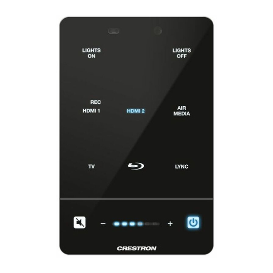
Crestron 3-Series Do Manual
Media presentation controller
Hide thumbs
Also See for 3-Series:
- Operation manual (62 pages) ,
- Supplemental manual (20 pages) ,
- Quick start manual (8 pages)
Advertisement
Quick Links
DO
GUIDE
MPC3-201
3-Series
Media Presentation Controller 201
®
DO
Attach the Mounting Plate
The Crestron
MPC3-201 3-Series
media presentation controller is designed to install into a 1-gang
®
®
European electrical box. Use the two included 4B x 3/4" screws to attach the MPC3-201 mounting plate
to the electrical box.
Screws (2):
Mounting
4B x 3/4"
plate
DO
Connect the Device
Route all necessary cables through the rear of the electrical box, and then make connections to the
MPC3-201 as shown in the following illustration.
NOTE:
All cable connections must be made prior to attaching the MPC3-201 assembly to the electrical
box.
LAN PoE:
10BASE-T / 100BASE-TX
Ethernet to LAN
A single Ethernet cable provides power and data to the MPC3-201. A Crestron PoE (Power over Ethernet)
power supply, such as the PWE-4803RU, or a PoE-capable network switch is recommended (both sold
separately). Apply power to the MPC3-201 after all connections have been made.
NOTE:
Use Crestron power supplies for Crestron equipment.
NOTE:
Ensure that the MPC3-201 is properly grounded. Insert the 6-32 x 1/4" SEMS screw through the
terminal ring end of the included grounding cable, and then attach the screw to the hole in the rear of
the assembly. (Refer to the illustration above.) Then, attach the other end of the cable to an earth ground
(building steel).
DO
Complete the Installation
1.
Once all cable connections have been made, use four of the included 4-40 x 1/4" Phillips
screws to attach the assembly to the mounting plate.
1-gang
European
electrical box
Screws (4):
4-40 x 1/4"
2.
Punch out the desired icon chips from the icon packaging sheet, and then insert the chips,
bottom side first, into the appropriate label holders on the rear of the assembly.
Icon chip
Attach
grounding
cable here
(with
6-32 x 1/4"
SEMS screw)
Optional custom-engraved icon chips for the MPC3-201 can be designed and ordered
NOTE:
separately by downloading the Crestron Engraver software from www.crestron.com/software.
NOTE:
To remove an icon chip from a label holder, carefully pull the top of the chip away from
the assembly so that it can be grasped, and then pull the chip upward and out of the holder.
DO
Check the Box
QUANTITY
PRODUCT
1
Bit, Torx
®
, T8, Security
1
Cable, Grounding
1
Icon Chips, 30 Piece Set
1
Screw, 4-40 x 1/4", Flat Head, Torx
5
Screw, 4-40 x 1/4", Undercut Head, Phillips
2
Screw, 4B x 3/4", Flat Head, Phillips
1
Screw, 6-32 x 1/4", Pan Head, SEMS
Mounting
plate
Assembly
Label
holders (6)
Assembly
(rear view)
COLOR
Black
Black
Black
3.
Hold the magnetic bezel over the assembly, and then attach the bezel to the assembly, top
side first, until the bezel magnetically snaps into place against the assembly.
Attach the top side
of the bezel to the
assembly rst
Bezel
NOTE:
If the bezel is removed and then reattached to the assembly, there is a 20-second
delay before the buttons are functional.
4.
(Optional) For a secure installation, screw either the remaining 4-40 x 1/4" Phillips screw or the
Torx
security screw (both included) into the screw hole on the bottom of the bezel to secure
®
the bezel to the assembly.
Insert security
screw here
Bezel and
assembly
(bottom view)
NOTE:
To remove the bezel from the assembly for accessing the icon chips and the reset
buttons, unscrew the security screw from the bottom of the bezel (if installed), and then gently
pull the bezel, bottom side first, away from the assembly until the magnetic hold is broken.
PART NUMBER
2025915
4509212
4526558
2025311
2007152
2019088
2007214
Assembly
Advertisement

Summary of Contents for Crestron 3-Series
- Page 1 A single Ethernet cable provides power and data to the MPC3-201. A Crestron PoE (Power over Ethernet) power supply, such as the PWE-4803RU, or a PoE-capable network switch is recommended (both sold separately).
- Page 2 Crestron, the Crestron logo, 3-Series, Crestron Fusion, Crestron Toolbox, and the MPC logo are either trademarks or registered trademarks of Crestron Electronics, Inc., in the United States and/or other countries.


