Crestron 3 Series Do Manual
Room media controller
Hide thumbs
Also See for 3 Series:
- Reference manual (68 pages) ,
- Operation manual (48 pages) ,
- Supplemental manual (22 pages)
Advertisement
Quick Links
DO
GUIDE
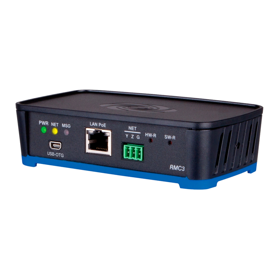
RMC3
3-Series
Room Media Controller
®
DO
Install the Device
The Crestron
®
RMC3 can be mounted onto a flat surface or
a standard DIN rail using the included mounting bracket. The
RMC3 is shipped with the mounting bracket attached.
CAUTION:
To prevent overheating, do not operate this product
in an area that exceeds the environmental temperature range
listed on the product web page.
NOTE:
Rack mount and pole mount kits (sold separately) are
also available as mounting options for the RMC3.
Surface Mounting
To mount the RMC3 onto a flat surface, use the following
procedure. (Refer to the image below.)
1. Detach the RMC3 from the mounting bracket by pulling the
left and right flanges of the bracket outward to release the
tabs that hold the RMC3 in place.
2. Attach the mounting bracket to the flat surface using the
four mounting holes in each corner of the bracket and the
appropriate mounting screws (not included).
3. Align the slots on the bottom of the RMC3 with the RMC3
mounting tabs on the bracket, and then press the RMC3
into the bracket until the RMC3 snaps into place.
4. (Optional) Secure the RMC3 in the mounting bracket by
screwing the two included 6-32 x 3/8" Phillips pan head
screws into the holes on the left and right of the assembly.
Left
ange
Right
ange
Mounting
bracket
Screws, Phillips
pan head (2):
6-32 x 3/8"
DO
QTY PRODUCT
1
1
1
2
DIN Rail Mounting
2
To mount the RMC3 onto a DIN
1
rail, use the following procedure.
2
(Refer to the image below.)
1. Detach the RMC3 from the
mounting bracket by pulling the left and right flanges of the
bracket outward to release the tabs that hold the RMC3 in
place.
2. Using a flat-head screwdriver, pull the DIN rail release tab
downward.
3. Position the DIN rail mounting tabs (located on the rear of
the bracket, not shown) over the top edge of the DIN rail,
and then push the DIN rail release tab upward to lock the
mounting bracket onto the rail.
4. Align the slots on the bottom of the RMC3 with the RMC3
mounting tabs on the bracket, and then press the RMC3
into the bracket until the RMC3 snaps into place.
5. (Optional) Secure the RMC3 in the mounting bracket by
screwing the two included 6-32 x 3/8" Phillips pan head
screws into the holes on the left and right of the assembly.
Mounting
Screws, Phillips
bracket
pan head (2):
6-32 x 3/8"
Right
ange
Left
ange
DIN rail
DIN rail
release tab
(not included)
DO
Make Connections
Make any necessary connections as called out in the diagrams
to the right. Apply power after all connections have been made.
NOTE:
A power supply is not included. The device requires a
PoE injector or a PoE switch (both sold separately).
Check the Box
Adapter, USB to USB Mini
Bracket, Mounting, Integrated DIN Rail Clip
Cable, USB 2.0, A - Mini B, 6' 6" (2 m)
Connector, 3-Pin
Connector, 4-Pin
Connector, 5-Pin
Screw, 6-32 x 3/8", Pan Head, Phillips
NOTE:
Ensure the unit is properly grounded by connecting the
chassis ground lug to an earth ground (building steel).
10 Base-T / 100 Base-TX
Ethernet to LAN
USB-OTG:
To computer console
or USB storage device
DIGITAL IN (1−2):
From control
devices
RELAY 1−2:
To controllable
devices
PORT RS-232
GND GND
TX
TX (from RMC3)
RX
RX (to RMC3)
RTS RTS (from RMC3)
CTS CTS (to RMC3)
1. RS-422 transmit and receive are balanced signals requiring two lines plus a ground in
each direction. RXD+ and TXD+ should idle high (going low at start of data transmission).
RXD- and TXD- should idle low (going high at start of data transmission). If necessary,
RXD+/RXD- and TXD+/TXD- may be swapped to maintain correct signal levels.
2. A ground terminal connection is recommended but not required.
COLOR
PART NUM.
2037338
Black
4519035
Black
2025146
2003575
2003576
2003577
Black
2007225
LAN PoE:
NET:
To any Cresnet
®
network device
IR 1−2:
To IR controlled
devices
Ground
COM: To/from
RS-232/422/485
devices
COM 1 Connections
RS-422
1
RS-485
GND
GND
2
TX- (from RMC3)
TX-/RX-
RX+(to RMC3)
Not Used
TX+ (from RMC3) TX+/RX+
RX- (to RMC3)
Not Used
Advertisement

Related Manuals for Crestron 3 Series


Summary of Contents for Crestron 3 Series
- Page 1 Connector, 3-Pin 2003575 Install the Device DIN Rail Mounting Connector, 4-Pin 2003576 The Crestron ® RMC3 can be mounted onto a flat surface or To mount the RMC3 onto a DIN Connector, 5-Pin 2003577 a standard DIN rail using the included mounting bracket. The rail, use the following procedure.
- Page 2 However, there is no guarantee that interference will not may be used in this document to refer to either the entities claiming the marks and names or their products. Crestron disclaims any proprietary interest in the marks and names of others.