Crestron 3-Series Quick Start Manual
Hide thumbs
Also See for 3-Series:
- Operation manual (62 pages) ,
- Supplemental manual (20 pages) ,
- Quick start manual (8 pages)
Advertisement
Quick Links
AV3 and PRO3
3-Series® Control System
The Crestron®
AV3
and
PRO3
are rack-mountable 3-Series control
processors offering immense power, expanded memory, numerous
integrated control ports, and optional control card expansion slots.
In the Box
1
AV3 or PRO3, 3-Series Control System
Additional Items
2
Bracket, Rack Ear, 2U (2032678)
4
Foot, 0.5 in. x 0.5 in. x 0.23 in., Adhesive (2002389)
4
Connector, 3-Pin (2003575)
1
Connector, 4-Pin (2003576)
2
Connector, 5-Pin (2003577)
4
Connector, 8-Pin (2003580)
1
Connector, 9-Pin (2003581)
1
Cable, Power, 6 ft 7 in. (2 m) (2001134)
Install the Device
The control system can be mounted into a rack or placed on a flat
surface.
Mount into a Rack
The control system occupies 2U of rack space. Use the three screws from
the front part of each side panel, and a #1 or #2 Phillips screwdriver to
attach the two included rack ears to the device, as shown in the following
illustration. Then mount the device into the rack using four mounting
screws (not included).
Rack Mounting Safety Precautions
Elevated Operating Ambient Temperature: If installed in a closed or
multi-unit rack assembly, the operating ambient temperature of the rack
environment may be greater than room ambient temperature. Therefore,
consideration should be given to installing the equipment in an
environment compatible with the maximum ambient temperature (Tma)
specified by the manufacturer.
Reduced Airflow: Installation of the equipment in a rack should be such
that the amount of airflow required for safe operation of the equipment
is not compromised.
Quick Start
1
Advertisement

Related Manuals for Crestron 3-Series


Summary of Contents for Crestron 3-Series
- Page 1 In the Box Mount into a Rack AV3 or PRO3, 3-Series Control System The control system occupies 2U of rack space. Use the three screws from the front part of each side panel, and a #1 or #2 Phillips screwdriver to...
- Page 2 Quick Start AV3 and PRO3 3-Series® Control System Mechanical Loading: Mounting of the equipment in the rack should be such that a hazardous condition is not achieved due to uneven mechanical loading. Circuit Overloading: Consideration should be given to the connection of the equipment to the supply circuit and the effect that overloading of the circuits might have on overcurrent protection and supply wiring.
-
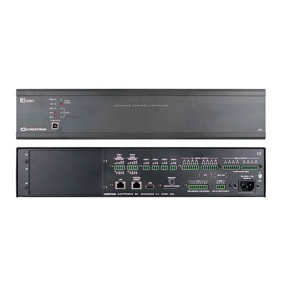
Page 3: Connect The Device
Quick Start AV3 and PRO3 3-Series® Control System Connect the Device Connect the Control System Connect the device as called out in the following illustrations. Connect power last. AV3 Front Panel PRO3 Front Panel... - Page 4 Quick Start AV3 and PRO3 3-Series® Control System Rear Panel Connections NOTE: Ensure the unit is properly grounded by connecting the chassis ground lug to an earth ground (building steel).
-
Page 5: Configure The Device
If necessary, RXD+/RXD- and TXD+/TXD- may be swapped to maintain correct signal levels. 1. Use Crestron Toolbox to set the time zone. For details, refer to the 2. A ground terminal connection is recommended but not required. Ground potential Crestron Toolbox help file. - Page 6 Use the front panel navigation pad and LCD display to configure and monitor the PRO3's operations. For details, refer to the PRO3 Supplemental Guide (Doc. 7330) at www.crestron.com/manuals. 4. Click the following options from the setup menu to configure the...
- Page 7 Crestron disclaims any proprietary interest in the marks and names of others. Crestron is not responsible for errors in typography or photography.