Table of Contents
Advertisement
Quick Links
Advertisement
Chapters
Table of Contents

Related Manuals for IBASE Technology IB704


Summary of Contents for IBASE Technology IB704
- Page 1 IB704 AMD Geode LX800 PC/104-Plus CPU Module USER’S MANUAL Version 1.0...
- Page 2 Acknowledgments Award is a registered trademark of Award Software International, Inc. PS/2 are trademarks of International Business Machines Corporation. Crusoe and LongRun are registered trademarks of Transmeta Corporation. Microsoft Windows is a registered trademark of Microsoft Corporation. Winbond is a registered trademark of Winbond Electronics Corporation.
-
Page 3: Table Of Contents
Checklist ................2 Specifications ..............3 Board Dimensions ............... 4 Installations ............5 Installing the Memory (SODIMM) ........6 Jumpers and Connector on IB704 ........7 BIOS Setup ............17 Drivers Installation ........35 Entertainment Encryption/Decryption Controller Driver . 36 VGA Drivers Installation .......... - Page 4 This page is intentionally left blank. IB704 User’s Manual...
-
Page 5: Introduction
AMD Geode LX 800@0.9W processor. With a compact 90mm x 96mm footprint standard, the IB704 is suited for space-constraint applications in factory automation, military, security, transportation and POS. The board does... -
Page 6: Checklist
INTRODUCTION Checklist Your IB704 package should include the items listed below. Damaged or missing items should be reported to your supplier. The IB704 CPU Module This User’s Manual One Driver CD Optional cable kit (IDE7, IDE6, PK3-2, PS2G, VGA8, RJ45A2, USB2-2, PK1-12, FF2) IB704 User’s Manual... -
Page 7: Specifications
INTRODUCTION Specifications PC/104+ Form Factor AMD Geode LX processor CPU Type LX800 @500MHz (IB704F) CPU Operating LX700 @433MHz (IB704) Frequency APM1.2 Green / APM Award BIOS (4MB FWH) BIOS AMD CS5536 I/O companion multi-function south Chipset bridge One DDR SODIMM socket, Max. Up to 1GB... -
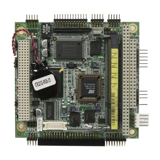
Page 8: Board Dimensions
INTRODUCTION Board Dimensions IB704 User’s Manual... -
Page 9: Installations
INSTALLATIONS Installations This section provides information on how to use the jumpers and connectors on the IB704 in order to set up a workable system. The topics covered are: Installing the Memory (SODIMM) ..........6 Jumpers and Connector on IB704 ..........7... -
Page 10: Installing The Memory (Sodimm)
INSTALLATIONS Installing the Memory (SODIMM) The IB704 has a 144-pin SODIMM socket. The SODIMM socket supports a maximum total memory of 1GB. Installing and Removing DIMMs To install the SODIMM, locate the memory slot on the CPU module and perform the following steps: 1. -
Page 11: Jumpers And Connector On Ib704
INSTALLATIONS Jumpers and Connector on IB704 Jumpers are used on the IB704 to select various settings and features according to your needs and applications. Contact your supplier if you have doubts about the best configuration for your needs. The following lists the connectors on IB704 and their respective functions. -
Page 12: Jumper And Connector Locations On Ib704
INSTALLATIONS Jumper and Connector Locations on IB704 Jumper and Connectors on IB704 ................Page J15 & J16: PC/104 Connector ..................9 PC/104-Plus Bus Signal Assignments ................. 10 PC/104 Bus Signal (Reference Only)................11 JP1: Clear CMOS Content ..................12 JP2: Panel Power Setting .................... 12 FDD1: Floppy Drive Connector ................. -
Page 13: J15 & J16: Pc/104 Connector
-12V LA19 IRQ15 LA18 IRQ14 +12V LA17 DACK0 IOCHRDY MEMR DRQ0 SMEMW MEMW DACK5 SMEMR DRQ5 DACK6 DRQ6 ZA15 A16 DACK3 DACK7 DRQ3 DRQ7 DACK1 DRQ1 MASTER REFRESH KEY PIN IRQ7 IRQ6 IRQ5 IRQ4 IRQ3 DACK2 BALE IB704 User’s Manual... -
Page 14: Pc/104-Plus Bus Signal Assignments
5.0V I/O signals and Pin-D30 will be modified in the same manner for 3.3V I/O. It is recommended that both KEY pins (A1 and D30) be electrically connnected for GND for shielding. IB704 User’s Manual... -
Page 15: Pc/104 Bus Signal (Reference Only)
LA18 SA15 DRQ3 DACK0* LA17 SA14 DACK1* DRQ0 MEMR* SA13 DRQ1 DACK5* MEMW* SA12 REFRESH* DRQ5 SA11 SYSCLK DACK6* SA10 IRQ7 DRQ5 SD10 IRQ6 DACK7* SD11 IRQ5 DRQ7 SD12 IRQ4 SD13 IRQ3 MASTER* SD14 DACK2* SD15 BALE IB704 User’s Manual... -
Page 16: Jp1: Clear Cmos Content
JP2: Panel Power Setting Setting Function Pin 1-2 Short/Closed Pin 2-3 +3.3V Short/Closed FDD1: Floppy Drive Connector Signal Name Pin # Pin # Signal Name INDEX DRV_SEL DSK_CH MOTOR DINST STEP WDATA EGATE TRACK WPROT RDATA SIDE IB704 User’s Manual... -
Page 17: Ide1: Ide Connector
Address 0 Address 2 Chip select 0 Chip select 1 Activity Ground Ground N.C. J1: Buzzer Connector Signal Name Buzzer+ Buzzer- J3: PC/104+ PCI J4, J5: USB Connector Signal Name Signal Name USB Power Ground Ground USB Power IB704 User’s Manual... -
Page 18: J6: Lan Connector
No connect Active LED+ No connect J8: LVDS Connector Signal Name Pin # Pin # Signal Name TX0- TX0+ Ground Ground TX1- TX1+ 5V/3.3V Ground TX3- TX3+ TX2- TX2+ Ground Ground TXC- TXC+ 5V/3.3V ENABKL +12V +12V IB704 User’s Manual... -
Page 19: J9: Parallel Port Connector
RTS, Request to send CTS, Clear to send RI, Ring indicator No Connect. J12: Front I/O Connector Signal Name Signal Name HDD LED+ Power LED+ HDD LED- Power LED- Reset- No connect Reset+ No connect No connect No connect IB704 User’s Manual... -
Page 20: J14: Vga Connector
J17: Power Connector Signal Name Ground Ground +12V J18: IrDA Connector Pin # Signal Name No connect Ir RX Ground Ir TX J19: Keyboard/Mouse Connector Pin # Signal Name Keyboard Data Keyboard Clock Mouse Data Mouse Clock Ground IB704 User’s Manual... -
Page 21: Bios Setup
............... 30 PNP/PCI Configurations ..............31 PC Health Status ................32 Load Fail-Safe Defaults ..............33 Load Optimized Defaults ..............33 Set Supervisor/User Password ............33 Save & Exit Setup ................33 Exit Without Saving ................. 33 IB704 User’s Manual... -
Page 22: Bios Introduction
<PgUp> and <PgDn> keys to change entries, <F1> for help and <Esc> to quit. When you enter the Setup utility, the Main Menu screen will appear on the screen. The Main Menu allows you to select from various setup functions and exit choices. IB704 User’s Manual... - Page 23 These defaults have been carefully chosen by both Award and your system manufacturer to provide the absolute maximum performance and reliability. Changing the defaults could cause the system to become unstable and crash in some cases. IB704 User’s Manual...
-
Page 24: Standard Cmos Setup
Sun to Sat Month : 1 to 12 Date : 1 to 31 Year : 1999 to 2099 To set the date, highlight the “Date” field and use the PageUp/ PageDown or +/- keys to set the current time. IB704 User’s Manual... - Page 25 These fields identify the types of floppy disk drive A or drive B that has been installed in the computer. The available specifications are: 360KB 1.2MB 720KB 1.44MB 2.88MB 5.25 in. 5.25 in. 3.5 in. 3.5 in. 3.5 in. IB704 User’s Manual...
- Page 26 The system boot will not be halted for a disk error; it will stop for all other errors. All, But Disk/Key The system boot will not be halted for a key- board or disk error; it will stop for all others. IB704 User’s Manual...
-
Page 27: Advanced Bios Features
SCSI, CDROM, HDD-1, HDD-2, HDD-3, ZIP100, USB-FDD, LAN, USB-CDROM, USB-HDD and Disable. Boot Other Device These fields allow the system to search for an OS from other devices other than the ones selected in the First/Second/Third Boot Device. IB704 User’s Manual... - Page 28 Setup. When you select System, the system prompts for the User Password every time you boot up. When you select Setup, the system always boots up and prompts for the Supervisor Password only when the Setup utility is called up. IB704 User’s Manual...
- Page 29 OS/2 that depends on certain BIOS calls to access memory. The default setting is Non-OS/2. Small Logo (EPA) Show The EPA logo appears at the right side of the monitor screen when the system is boot up. IB704 User’s Manual...
-
Page 30: Advanced Chipset Features
This options for this field are Flat Panel, CRT and Panel & CRT. For flat panel, configuration settings include Flat Panel Type, Resolution (320x240 up to 1600x1200), Data Bus Type, Refresh Rate (60~100Hz), HSYNC Polarity, VSYNC Polarity, SHFCLK Active Period and LP Active Period. IB704 User’s Manual... - Page 31 Memory Hole At 15M-16M In order to improve performance, certain space in memory can be reserved for ISA cards. This memory must be mapped into the memory space below 16 MB. The choices are Enabled and Disabled. IB704 User’s Manual...
- Page 32 This field allows your hard disk controller to use the fast block mode to transfer data to and from your hard disk drive. Onboard LAN Boot ROM This feature allows users to enable or disable the onboard LAN boot ROM. The default setting is Disabled IB704 User’s Manual...
- Page 33 This field determines the UART 2 mode in your computer. The default value is Normal. Other options include IrDA and ASKIR. Parallel Port Mode This field allows you to determine parallel port mode function. Standard Printer Port Enhanced Parallel Port Extended Capabilities Port IB704 User’s Manual...
-
Page 34: Power Management Setup
The Instant Off mode allows powering off immediately upon pressing the power button. In the Delay 4 Sec mode, the system powers off when the power button is pressed for more than four seconds or enters the suspend mode when pressed for less than 4 seconds. IB704 User’s Manual... -
Page 35: Pnp/Pci Configurations
This field allows you to set whether or not MPEG ISA/VESA VGA cards can work with PCI/VGA. When this field is enabled, a PCI/VGA can work with an MPEG ISA/VESA VGA card. When this field is disabled, a PCI/VGA cannot work with an MPEG ISA/VESA card. IB704 User’s Manual... -
Page 36: Pc Health Status
Temperatures/Voltages These fields are the parameters of the hardware monitoring function feature of the motherboard. The values are read-only values as monitored by the system and show the PC health status. IB704 User’s Manual... -
Page 37: Load Fail-Safe Defaults
Select this option to exit the Setup utility without saving the changes you have made in this session. Typing “Y” will quit the Setup utility without saving the modifications. Typing “N” will return you to Setup utility. IB704 User’s Manual... - Page 38 BIOS SETUP This page is intentionally left blank. IB704 User’s Manual...
-
Page 39: Drivers Installation
If you find the items missing, please contact the vendor where you made the purchase. The contents of this section include the following: Entertainment Encryption/Decryption Controller Driver ... 36 VGA Drivers Installation ............38 IB704 User’s Manual... -
Page 40: Entertainment Encryption/Decryption Controller Driver
1. In the Windows operating system, go to the Device Manager. 2. As shown below, click the Entertainment Encryption/Decryption Controller under Other devices. 3. In the following window, click the Driver tab and click OK to continue. IB704 User’s Manual... - Page 41 (Advanced). Click Browse to find the driver’s path in the CD provided - \AMD\AES. Then, click Next to start the drivers installtion. Then click Finish after the wizard has finished installing the software for Geode LX AES Crypto Driver. IB704 User’s Manual...
-
Page 42: Vga Drivers Installation
1. In the Windows operating system, go to the Device Manager. 2. As shown below, click the Video Controller (VGA Compatible under Other devices. 3. In the following window, click the Driver tab and click OK to continue. IB704 User’s Manual... - Page 43 DRIVERS INSTALLATION 4. In the Hardware Update Wizard, select No, not this time and click Next to continue. Then select Install from a list of specific location (Advanced). IB704 User’s Manual...
- Page 44 CD provided or enter the path directly - \AMD\Vga\. Then, click Next to start the drivers installtion. Then click Finish after the wizard has finished installing the software for Advanced Micro Devices Win XP Graphics Driver. IB704 User’s Manual...
- Page 45 DRIVERS INSTALLATION This page is intentionally left blank. IB704 User’s Manual...
-
Page 46: Appendix
Coprocessor 01F0h – 01F7h IDE (Primary) 03F6h 02F8h - 02FFh Serial Port #2(COM2) 0378h – 037Ah Parallel Port #1(LPT1) 03C0h – 03DFh Reserved for VGA 03F0h – 03F5h FDD Controller 03F7h 03F8h - 3FFh Serial Port #1(COM1) IB704 User’s Manual... -
Page 47: Interrupt Request Lines (Irq)
Serial Port #2 IRQ4 Serial Port #1 IRQ5 For PCI IRQ6 Floppy Disk Controller IRQ7 Parallel Port #1 IRQ8 Real Time Clock IRQ9 For PCI IRQ10 For PCI IRQ11 For PCI IRQ12 PS/2 Mouse IRQ13 Coprocessor IRQ14 Primary IDE IB704 User’s Manual... -
Page 48: Watchdog Timer Configuration
;switch to LD8 mov cl, 0F5h call Read_Reg and al, NOT 08h call Write_Reg ;set count mode as second pop ax mov cl, 0F6h call Write_Reg ;set watchdog timer mov al, 01h mov cl, 30h call Write_Reg ;watchdog enabled IB704 User’s Manual... - Page 49 ; IN : None ; OUT : None ;[]=============================================== Unlock_Chip Proc Near mov dx, 4Eh mov al, 87h out dx, al out dx, al Unlock_Chip Endp ;[]================================================ ; Name : Lock_Chip ; IN : None ; OUT : None IB704 User’s Manual...
- Page 50 : Read_Reg ; IN : CL - register index ; OUT : AL - Value to read ;[]=================================================== Read_Reg Proc Near mov al, cl mov dx, 4Eh out dx, al inc dx al, dx Read_Reg Endp ;[]================================================ IB704 User’s Manual...
- Page 51 APPENDIX This page is intentionally left blank. IB704 User’s Manual...