
Related Manuals for IBASE Technology IB981AF-C226


Summary of Contents for IBASE Technology IB981AF-C226
- Page 1 IB981 Gen. Core™ i7/i5/i3/ ® Intel ® ® Pentium / Celeron Full-Size CPU Card User’s Manual Version 1.0 (Sep. 2017)
- Page 2 No part of this publication may be reproduced, copied, stored in a retrieval system, translated into any language or transmitted in any form or by any means, electronic, mechanical, photocopying, or otherwise, without the prior written consent of IBASE Technology, Inc. (hereinafter referred to as “IBASE”). Disclaimer IBASE reserves the right to make changes and improvements to the products described in this document without prior notice.
-
Page 3: Compliance
Compliance In a domestic environment, this product may cause radio interference in which case users may be required to take adequate measures. This product has been tested and found to comply with the limits for a Class B device, pursuant to Part 15 of the FCC Rules. These limits are designed to provide reasonable protection against harmful interference in a residential installation. -
Page 4: Important Safety Information
Important Safety Information Carefully read the precautions before using the board. Environmental conditions: • Use this product in environments with ambient temperatures between 0˚C and 60˚C. • Do not leave this product in an environment where the storage temperature may be below -20° C or above 80° C. To prevent from damages, the product must be used in a controlled environment. -
Page 5: Warranty Policy
Warranty Policy • IBASE standard products: 24-month (2-year) warranty from the date of shipment. If the date of shipment cannot be ascertained, the product serial numbers can be used to determine the approximate shipping date. • -party parts: 12-month (1-year) warranty from delivery for the 3 -party parts that are not manufactured by IBASE, such as CPU, CPU cooler, memory, storage devices, power adapter, panel and touchscreen. -
Page 6: Table Of Contents
Table of Contents Compliance ..................iii Important Safety Information ............iv Warranty Policy ................v Technical Support & Services ............v Chapter 1 General Information ..........1 Introduction ..................2 Features ..................... 2 Packing List ..................3 Optional Accessories ................3 Specifications .................. - Page 7 2.5.6 Front Panel Setting Connector (J3) ........22 2.5.7 External Audio Connector (J6) ..........23 2.5.8 ATX 12V Power Connector (J12) .........24 2.5.9 Digital I/O 4 In/4 Out (J11) ...........24 2.5.10 PS/2 KB & MS Connector (J9) ..........25 2.5.11 Parallel Port (J5) ..............26 2.5.12 DVI-D Port (J15) ..............27 2.5.13...
- Page 8 4.4.2 System Agent (SA) Configuration ........66 Boot Settings ..................68 Security Settings ................69 Save & Exit Settings ................. 70 Appendix ..................73 I/O Port Address Map ............... 74 Interrupt Request Lines (IRQ) ............78 Watchdog Timer Configuration ............80 On-Board Connector Types ..............
-
Page 9: Chapter 1 General Information
Chapter 1 General Information The information provided in this chapter includes: • Features • Packing List • Optional Accessories • Block Diagram • Specifications • Board Overview • Board Dimensions... -
Page 10: Introduction
Introduction The IB981 PICMG1.0 SHB Express CPU Card is based on the Gen. Core™ i7/i5/i3 family, Pentium ® ® ® platform of Intel or Celeron processor and features an integrated graphics core that work with VGA, DVI-D and LVDS display outputs. It is able to be operated at the °C °C ambient operating temperature ranging from 0... -
Page 11: Packing List
General Information Packing List Your IB981 package should include the items listed below. If any of the items below is missing, contact the distributor or dealer from whom you purchased the product. • IB981 PICMG1.0 SHB • Cable Kit (IB73-1) Including COM Port Cable (PK1-20BK) P/S2 KB &... -
Page 12: Specifications
Specifications Product Name IB981AF-C226 IB981AF IB981F Form Factor PICMG 1.0 SHB Express full-size CPU card System • Windows 10 (64-bit) Operating • Windows 7 Pro (32-bit / 64-bit) System • Linux Ubuntu (64-bit) ® ® ® Intel Gen. Core i7/i5/i3, Pentium... - Page 13 General Information Product Name IB981AF-C226 IB981AF IB981F I/O Ports • 1 x VGA • Display 1 x DVI-D (header on board) • 1 x 24-bit dual channel LVDS 2 x RJ45 GbE LAN 4 x USB 3.0: 2 x USB 3.0: via I/O coastline •...
-
Page 14: Block Diagram
Block Diagram IB981 User’s Manual... -
Page 15: Overview
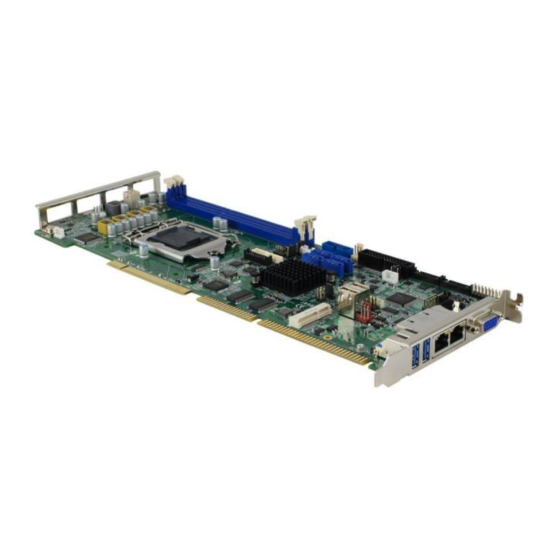
General Information Overview Top View Photo of IB981AF Series I/O View Oblique View Photo of IB981AF Series *The photos above are for reference only. Some minor components may differ. IB981 User’s Manual... -
Page 16: Dimensions
Dimensions Board diagram of IB981A IB981 User’s Manual... -
Page 17: Chapter 2 Hardware Configuration
Chapter 2 Hardware Configuration This section provides information on jumper settings and connectors on the IB981 in order to set up a workable system. On top of that, you will also need to install crucial pieces such as the CPU and the memory before using the product. The topics covered are: •... -
Page 18: Essential Installations Before You Begin
Essential Installations Before You Begin Follow the instructions below to install the CPU and the memory. 2.1.1 Installing the CPU Follow the instructions below to install the CPU. Unlock the socket by pressing the lever sideways, then lift up the lever and the metal lid. -
Page 19: Installing The Memory
Hardware Configuration 2.1.2 Installing the Memory To install the modules, locate the memory slot on the board and perform the following steps: Hold the module so that the key of the module aligned with that on the memory slot. Gently push the module in an upright position until the clips of the slot close to hold the module in place when the module touches the bottom of the slot. -
Page 20: Setting The Jumpers
Setting the Jumpers Set up and configure your IB981 by using jumpers for various settings and features according to your needs and applications. Contact your supplier if you have doubts about the best configuration for your use. 2.2.1 How to Set Jumpers Jumpers are short-length conductors consisting of several metal pins with a non-conductive base mounted on the circuit board. -
Page 21: Jumper & Connector Locations On Ib981
Hardware Configuration Jumper & Connector Locations on IB981 Board diagram of IB981AF IB981 User’s Manual... -
Page 22: Jumpers Quick Reference
Jumpers Quick Reference Function Jumper Name Page Clearing CMOS Data JBAT1 COM1 RS-232 Power Setting Backlight Power Mode Selection Backlight Control Setting LVDS Panel Power Selection Factory Use Only JP7, JP9, JP11 2.4.1 Clear CMOS Content (JBAT1) Function Pin closed Illustration Normal (default) -
Page 23: Com1 Rs232 Power Setting (Jp1)
Hardware Configuration 2.4.2 COM1 RS232 Power Setting (JP1) Function Pin closed Illustration +12V (default) 2.4.3 Backlight Power Mode Selection (JP4) Function Pin closed Illustration DC Mode (default) PWM Mode IB981 User’s Manual... -
Page 24: Backlight Control Setting (Jp5)
2.4.4 Backlight Control Setting (JP5) Function Pin closed Illustration 3.3V Open (default) Close 2.4.5 LVDS Panel Power Selection (JP6) Function Pin closed Illustration 3.3V (default) IB981 User’s Manual... -
Page 25: Connectors Quick Reference
Hardware Configuration Connectors Quick Reference Function Connector Name Page COM1 & COM2 Serial Port COM3 & COM4 Serial Port USB 3.0 / USB 2.0 Connector J17 (pin-header), USB 2.0 Ports CN8 (vertial) LCD Backlight Connector Front Panel Setting Connector External Audio Connector ATX 12V Power Connector Digital I/O 4 In/4 Out PS/2 KB &... -
Page 26: Com1 & Com2 Serial Port (J1)
2.5.1 COM1 & COM2 Serial Port (J1) COM1 (pin1 ~ pin10) supports RS-232/422/485. COM2 (pin11 ~ pin20) supports RS-232 only. Assignment Assignment DCD1 DSR1 RXD1 RTS1 TXD1 CTS1 DTR1 Ground DCD2 DSR2 RXD2 RTS2 TXD2 CTS2 DTR2 Ground Assignment RS-232 RS-422 RS-485 DATA-... -
Page 27: Com3 & Com4 Serial Port (J2)
Hardware Configuration 2.5.2 COM3 & COM4 Serial Port (J2) COM3 (pin1 ~ pin10) and COM4 (pin11 ~ pin20) support RS-232 only. Assignment Assignment DCD3 DSR3 RXD3 RTS3 TXD3 CTS3 DTR3 Ground DCD4 DSR4 RXD4 RTS4 TXD4 CTS4 DTR4 Ground IB981 User’s Manual... -
Page 28: Usb 3.0 / Usb 2.0 Connector (J4)
2.5.3 USB 3.0 / USB 2.0 Connector (J4) Assignment Assignment VCC (900mA) P2_U2_D+ P1_SSRX- P2_U2_D- P1_SSRX+ Ground Ground P2_SSTX+ P1_SSTX- P2_SSTX- P1_SSTX+ Ground Ground P2_SSRX+ P1_U2_D- P2_SSRX- P1_U2_D+ VCC (900mA) IB981 User’s Manual... -
Page 29: Usb2.0 Ports (J17, Cn8)
Hardware Configuration 2.5.4 USB2.0 Ports (J17, CN8) J17: (pin-header) CN8: (vertical) J17: Assignment Assignment VCC (500mA) VCC (500mA) Ground Ground 2.5.5 LCD Backlight Connector (J8) Assignment Assignment Backlight Power +12V Backlight Control (2A) Backlight Enable Ground IB981 User’s Manual... -
Page 30: Front Panel Setting Connector (J3)
2.5.6 Front Panel Setting Connector (J3) Assignment Assignment Speaker Out Ground Ground Ground Ground Ground PWR_SW Ground HDD LED + HDD LED - J3 is utilized for system indicators to provide light indication of the computer activities and switches to change the computer status. It provides interfaces for the following functions. -
Page 31: External Audio Connector (J6)
Hardware Configuration • Reset Switch (Pins 17 and 18) The reset switch allows you to reset the system without turning the main power switch off and then on again. Orientation is not required when making a connection to this header. •... -
Page 32: Atx 12V Power Connector (J12)
2.5.8 ATX 12V Power Connector (J12) J12 connector supplies the CPU operating voltage. Assignment Assignment Ground Ground +12V-IN +12V-IN 2.5.9 Digital I/O 4 In/4 Out (J11) Assignment Assignment Ground VCC (500mA) OUT3 OUT1 OUT2 OUT0 IB981 User’s Manual... -
Page 33: Ps/2 Kb & Ms Connector (J9)
Hardware Configuration 2.5.10 PS/2 KB & MS Connector (J9) Assignment Assignment VCC (300mA) VCC (300mA) MS_DATA KB_DATA MS_CLK KB_CLK Ground Ground IB981 User’s Manual... -
Page 34: Parallel Port (J5)
2.5.11 Parallel Port (J5) J5 is a 26-pin header used to connect to the optional printer port cable. Assignment Assignment Line printer strobe Auto Feed PD0, parallel data 0 Error PD1, parallel data 1 Initialize PD2, parallel data 2 Select PD3, parallel data 3 Ground PD4, parallel data 4... -
Page 35: Dvi-D Port (J15)
Hardware Configuration 2.5.12 DVI-D Port (J15) Assignment Assignment TDC1_B TDC1#_B Ground Ground TLC_B TLC#_B Ground HPDET_B N.C. TDC2_B TDC2#_B Ground Ground TDC0_B TDC0#_B N.C. N.C. SD_DDC_B SC_DDC_B IB981 User’s Manual... -
Page 36: Cpu Fan Power Connector (Cpu_Fan1)
2.5.13 CPU Fan Power Connector (CPU_FAN1) Assignment Assignment Ground Rotation detection +12V (1A) Control 2.5.14 System Fan Power Connector (SYS_FAN1) Assignment Assignment Ground Rotation detection +12V (1A) IB981 User’s Manual... -
Page 37: Lvds Connector (J13, J14)
Hardware Configuration 2.5.15 LVDS Connector (J13, J14) J13 (1 channel) J14 (2 channel) Assignment Assignment LD0+ LD0- Ground Ground LD1+ LD1- Ground Ground LD2+ LD2- Ground Ground CLK+ CLK- Ground Ground LD3+ LD3- LCD_PWR (1A) LCD_PWR (1A) IB981 User’s Manual... -
Page 38: Wake-On_Lan Connector (J19)
2.5.16 Wake-on_LAN Connector (J19) Assignment Assignment +5VSB -PME Ground 2.5.17 ATX 5V Power Connector (J18) Connect the J18 connector to the ATX power connector of your backplane. Assignment Assignment Ground +5VSB-IN PS_On IB981 User’s Manual... -
Page 39: Chapter 3 Drivers Installation
Chapter 3 Drivers Installation This chapter introduces installation of the following drivers: • ® Intel Chipset Software Installation Utility • Graphics Driver • HD Audio Driver • LAN Driver • ® Intel Management Engine Interface • ® Intel USB 3.0 Driver... -
Page 40: Introduction
Introduction This section describes the installation procedures for software and drivers. The software and drivers are included with the motherboard. If you find anything missing, please contact the distributor where you made the purchase. The contents of this section include the following: Note: After installing your Windows operating system, you must install first the Intel Chipset Software Installation Utility before proceeding with the drivers installation. - Page 41 Driver Installation Click Intel(R) Chipset Software Installation Utility. ® When the Welcome screen to the Intel Chipset Device Software appears, click Next to continue. Click Yes to accept the software license agreement and proceed with the installation process. On the Readme File Information screen, click Install for installation.
-
Page 42: Graphics Driver Installation
Graphics Driver Installation Click Intel and then Intel(R) 8 Series Chipset Drivers. Click Intel(R) HD Graphics Driver. IB981 User’s Manual... - Page 43 Driver Installation When the Welcome screen appears, click Next to continue. Click Yes to agree with the license agreement and continue the installation. On the Windows Security screen shown below, click Install to continue. The driver has been completely installed. Click Finish and restart the computer for changes to take effect.
-
Page 44: Hd Audio Driver Installation
HD Audio Driver Installation Click Intel and then Intel(R) 8 Series Chipset Drivers. Click Realtek High Definition Audio Driver. IB981 User’s Manual... - Page 45 Driver Installation On the Welcome screen of the InstallShield Wizard, click Yes for proceed. The installation is complete. Click Finish and restart the computer for changes to take effect. IB981 User’s Manual...
-
Page 46: Lan Driver Installation
LAN Driver Installation Click Intel and then Intel(R) 8 Series Chipset Drivers. Click Intel(R) PRO LAN Network Drivers. IB981 User’s Manual... - Page 47 Driver Installation ® On the screen of Intel Network Connections, click Install Drivers and Software. When the Welcome screen appears, click Next. Click Next to to agree with the license agreement. On the Setup Options screen, click the checkbox to select the desired driver(s) for installation.
-
Page 48: Intel ® Management Engine Interface
® Intel Management Engine Interface Before installation, please pay attention to the warning message below. Click Intel and then Intel(R) 8 Series Chipset Drivers. Click Intel(R) ME 9.0 Drivers. IB981 User’s Manual... - Page 49 Driver Installation ® When the Welcome screen to the InstallShield Wizard for Intel Management Engine Components appears, click Next. Click Yes to to agree with the license agreement. When the Setup Progress screen appears, click Next. IB981 User’s Manual...
- Page 50 As the driver has been sccessfully installed, click Finish and restart the computer for changes to take effect. IB981 User’s Manual...
-
Page 51: Intel ® Usb 3.0 Driver
Driver Installation ® Intel USB 3.0 Driver Click Intel and then Intel(R) 8 Series Chipset Drivers. Click Intel(R) USB 3.0 Drivers. IB981 User’s Manual... - Page 52 ® When the Welcome screen to the InstallShield Wizard for Intel USB 3.0 eXtensible Host Controller Driver appears, click Next. Click Yes to to agree with the license agreement. On the Readme File Information screen, click Next for installation. IB981 User’s Manual...
- Page 53 Driver Installation The driver has been successfully installed. Click Finish and restart the computer for changes to take effect. IB981 User’s Manual...
- Page 54 This page is intentionally left blank. IB981 User’s Manual...
-
Page 55: Chapter 4 Bios Setup
Chapter 4 BIOS Setup This chapter describes the different settings available in the AMI BIOS that comes with the board. The topics covered in this chapter are as follows: • Main Settings • Advanced Settings • Chipset Settings • Security Settings •... -
Page 56: Introduction
4.1 Introduction The BIOS (Basic Input/Output System) installed in the ROM of your ® computer system supports Intel processors. The BIOS provides critical low-level support for standard devices such as disk drives, serial ports and parallel ports. It also provides password protection as well as special support for detailed fine-tuning of the chipset controlling the entire system. - Page 57 BIOS Setup When you enter the BIOS Setup utility, the Main Menu screen will appear on the screen. The Main Menu allows you to select from various setup functions and exit choices. Warning: It is strongly recommended that you avoid making any changes to the chipset defaults.
-
Page 58: 4.3 Advanced Settings
4.3 Advanced Settings This section allows you to configure, improve your system and allows you to set up some system features according to your preference. IB981 User’s Manual... -
Page 59: Acpi Settings
BIOS Setup 4.3.1 ACPI Settings BIOS Setting Description Enable Hibernation Enables / Disables the system ability to hibernate (OS/S4 Sleep State). This option may be not effective with some OS. ACPI Sleep State Selects an ACPI sleep state where the system will enter when the Suspend button is pressed. -
Page 60: Trusted Computing
4.3.2 Trusted Computing BIOS Setting Description Security Device Enables / Disables TPM support. O.S. will Support not show TPM. Reset of platform is required. Note: This feature is not supported on IB981F. IB981 User’s Manual... -
Page 61: Wakeup Event Configuration
BIOS Setup 4.3.3 Wakeup Event Configuration BIOS Setting Description Wake up by PCI Wakes up the device by PCI PME#. PME# Wake up by PCIE Wakes up the device by PCIE WAKE#. WAKE# IB981 User’s Manual... -
Page 62: Cpu Configuration
4.3.4 CPU Configuration BIOS Setting Description Hyper-Threading Enabled for Windows XP and Linux (OS optimized for Hhyper-Threading Technology) and Disabled for other OS (OS not optimized for Hyper-Threading Technology). Active Processor Number of cores to enable in each processor Cores package. -
Page 63: Sata Configuration
BIOS Setup 4.3.5 SATA Configuration BIOS Setting Description SATA Controller(s) Enables / Disables SATA devices. SATA Mode Determines how the SATA controller(s) Selection operate. • AHCI Mode • RAID Mode Hot Plug Designates this port as Hot Pluggable. IB981 User’s Manual... -
Page 64: Lvds Configuration
4.3.6 LVDS Configuration BIOS Setting Description LVDS (eDP/DP) Enables / Disables LVDS (eDP/DP) device. Controller IB981 User’s Manual... -
Page 65: Ismart Configuration
BIOS Setup 4.3.7 iSmart Configuration BIOS Setting Description Power-On after Enables / Disables the system to be turned Power failure on automatically after a power failure. Power Resume Enables / Disables to delay the time for Delay system to turn on. Temperature Generate the reset signal when system Guardian... -
Page 66: Amt Configuration
4.3.8 AMT Configuration BIOS Setting Description Intel AMT Enables / Disables AMT configuration. Note: iAMT H/W is always enabled. This option just controls the BIOS extension execution. If enabled, this requires additional firmware in the SPI device. Hide Unconfigure Hides Unconfigures ME without password operation. -
Page 67: Usb Configuration
BIOS Setup 4.3.9 USB Configuration BIOS Setting Description Legacy USB Enables Legacy USB support. Support “Auto” disables legacy support if there is no USB device connected. “Disable” keeps USB devices available only for EFI applications. XHCI Hand-off This is a workaround for OSes without XHCI hand-off support. - Page 68 BIOS Setting Description Device reset Seconds of delaying execution of start unit time-out command to USB mass storage device. Device power-up The maximum time the device will take delay before it properly reports itself to the Host Controller. “Auto” uses default value for a Root port it is 100ms.
-
Page 69: F81846 Super Io Configuration
BIOS Setup 4.3.10 F81846 Super IO Configuration BIOS Setting Description Serial Port Sets parameters of Serial Ports. Enables / Configuration Disables the serial port and select an optimal setting for the Super IO device. BIOS Setting Description Multi Function There is a risk of permanent damage to electronic equipment if RS-232 equipment is connected to RS-422/485 equipment. -
Page 70: Hardware Monitor
4.3.11 Hardware Monitor BIOS Setting Description Smart Fan 1 / 2 Enables / Disables the smart fan feature. Function Options: Disabled (default) / 50 °C / 60 °C / 70 °C / 80 °C / 90 °C Temperatures/Voltages These fields are the parameters of the hardware monitoring function feature of the motherboard. -
Page 71: 4.4 Chipset Settings
BIOS Setup 4.4 Chipset Settings BIOS Setting Description PCH-IO PCH parameters Configuration System Agent (SA) System Agent (SA) parameters Configuration IB981 User’s Manual... -
Page 72: Pci Express Configuration
4.4.1 PCI Express Configuration BIOS Setting Description PCI Express PCI Express Configuration settings. Configuration IB981 User’s Manual... - Page 73 BIOS Setup 4.4.1.1. USB Configuration BIOS Setting Description USB Configuration Precondition work on USB host controller and root ports for faster enumeration. IB981 User’s Manual...
-
Page 74: System Agent (Sa) Configuration
4.4.2 System Agent (SA) Configuration BIOS Setting Description VT-d Checks if VT-d function on MCH is supported. IB981 User’s Manual... - Page 75 BIOS Setup 4.4.2.1. Graphics Configuration BIOS Setting Description Internal Graphics Keeps IGD enabled based on the setup options. 4.4.2.2. Memory Configuration IB981 User’s Manual...
-
Page 76: 4.5 Boot Settings
4.5 Boot Settings BIOS Setting Description Setup Prompt Number of seconds to wait for setup Timeout activation key. 65535(0xFFFF) means indefinite waiting. Bootup NumLock Selects the keyboard NumLock state. State Quiet Boot Enables / Disables Quiet Boot option. Fast Boot Enables / Disables boot with initialization of a minimal set of devices required to launch active boot option. -
Page 77: 4.6 Security Settings
BIOS Setup 4.6 Security Settings BIOS Setting Description Administrator Sets an administrator password for the setup Password utility. User Password Sets a user password. IB981 User’s Manual... -
Page 78: 4.7 Save & Exit Settings
4.7 Save & Exit Settings BIOS Setting Description Save Changes and Exits system setup after saving the changes. Exit Discard Changes Exits system setup without saving any and Exit changes. Save Changes and Resets the system after saving the changes. Reset Discard Changes Resets system setup without saving any... - Page 79 BIOS Setup BIOS Setting Description Save as User Saves the changes done so far as User Defaults Defaults. Restore User Restores the user defaults to all the setup Defaults options. IB981 User’s Manual...
- Page 80 This page is intentionally left blank. IB981 User’s Manual...
-
Page 81: Appendix
Appendix This section provides the mapping addresses of peripheral devices and the sample code of watchdog timer configuration. -
Page 82: I/O Port Address Map
I/O Port Address Map Each peripheral device in the system is assigned a set of I/O port addresses which also becomes the identity of the device. The following table lists the I/O port addresses used. Address Device Description 0x0000FFFF-0x0000FFFF Motherboard Resource 0x0000FFFF-0x0000FFFF Motherboard Resource 0x0000FFFF-0x0000FFFF... - Page 83 Appendix Address Device Description 0x00000680-0x0000069F Motherboard Resource 0x000004D0-0x000004D1 Programmable Interrupt Controller 0x000004D0-0x000004D1 Motherboard Resource 0x000003F8-0x000003FF Communications Port (COM1) 0x000003E8-0x000003EF Communications Port (COM3) 0x000003C0-0x000003DF Intel(R) HD Graphics P4600/P4700 0x000003B0-0x000003BB Intel(R) HD Graphics P4600/P4700 0x00000378-0x0000037F Printer Port (LPT1) 0x000002F8-0x000002FF Communications Port (COM2) 0x000002E8-0x000002EF Communications Port (COM4) 0x000002A0-0x000002AF...
- Page 84 Address Device Description 0x00000093-0x0000009F Memory Controller 0x00000092-0x00000092 Motherboard Resource 0x00000090-0x0000009F Motherboard Resource 0x0000008C-0x0000008E Motherboard Resource 0x00000088-0x00000088 Motherboard Resource 0x00000084-0x00000086 Motherboard Resource 0x00000081-0x00000091 Memory Controller 0x00000080-0x00000080 Motherboard Resource 0x00000080-0x00000080 Motherboard Resource 0x00000072-0x0000007F Motherboard Resource 0x00000070-0x00000070 Motherboard Resource 0x00000070-0x00000070 System CMOS/real time clock 0x00000067-0x00000067 Motherboard Resource 0x00000065-0x00000065...
- Page 85 Appendix Address Device Description 0x00000034-0x00000035 Programmable Interrupt Controller 0x00000030-0x00000031 Programmable Interrupt Controller 0x0000002E-0x0000002F Motherboard Resource 0x0000002C-0x0000002D Programmable Interrupt Controller 0x00000028-0x00000029 Programmable Interrupt Controller 0x00000024-0x00000025 Programmable Interrupt Controller 0x00000022-0x0000003F Motherboard Resource 0x00000020-0x00000021 Programmable Interrupt Controller 0x00000010-0x0000001F Motherboard Resource 0x00000000-0x0000001F Memory Controller 0x00000000-0x0000001F PCI Express Root Complex IB981 User’s Manual...
-
Page 86: Interrupt Request Lines (Irq)
Interrupt Request Lines (IRQ) Peripheral devices use interrupt request lines to notify CPU for the service required. The following table shows the IRQ used by the devices on board. Level Function IRQ 1 Standard PS/2 Keyboard IRQ 4294967293 Intel(R) 8 Series/C220 Series PCI Express Root Port #1 - 8C10 IRQ 4294967292 Intel(R) 8 Series/C220 Series PCI Express... - Page 87 Appendix Level Function IRQ 4294967286 Intel(R) Ethernet Connection I217-LM IRQ 19 Intel(R) Active Management Technology - SOL (COM5) IRQ 4294967294 Intel(R) Xeon(R) processor E3 - 1200 v3/4th Gen Core processor PCI Express x16 Controller - 0C01 IRQ 4294967285 Intel(R) I211 Gigabit Network Connection IRQ 4294967284 Intel(R) I211 Gigabit Network Connection IRQ 4294967283...
-
Page 88: Watchdog Timer Configuration
Watchdog Timer Configuration The Watchdog Timer (WDT) is used to generate a variety of output signals after a user programmable count. The WDT is suitable for use in the prevention of system lock-up, such as when software becomes trapped in a deadlock. Under these sorts of circumstances, the timer will count to zero and the selected outputs will be driven. - Page 89 Appendix DisableWDT(); return 0; //--------------------------------------------------------------------------- void EnableWDT(int interval) unsigned char bBuf; bBuf = Get_F81866_Reg(0x2B); bBuf &= (~0x20); Set_F81866_Reg(0x2B, bBuf); //Enable WDTO Set_F81866_LD(0x07); //switch to logic device 7 Set_F81866_Reg(0x30, 0x01); //enable timer bBuf = Get_F81866_Reg(0xF5); bBuf &= (~0x0F); bBuf |= 0x52; Set_F81866_Reg(0xF5, bBuf);...
- Page 90 //--------------------------------------------------------------------------- unsigned int Init_F81866(void) unsigned int result; unsigned char ucDid; F81866_BASE = 0x4E; result = F81866_BASE; ucDid = Get_F81866_Reg(0x20); if (ucDid == 0x07) //Fintek 81866 goto Init_Finish; F81866_BASE = 0x2E; result = F81866_BASE; ucDid = Get_F81866_Reg(0x20); if (ucDid == 0x07) //Fintek 81866 goto Init_Finish;...
- Page 91 Appendix //--------------------------------------------------------------------------- #ifndef __F81866_H #define __F81866_H //--------------------------------------------------------------------------- #define F81866_INDEX_PORT (F81866_BASE) #define F81866_DATA_PORT (F81866_BASE+1) //--------------------------------------------------------------------------- #define F81866_REG_LD 0x07 //--------------------------------------------------------------------------- #define F81866_UNLOCK 0x87 #define F81866_LOCK 0xAA //--------------------------------------------------------------------------- unsigned int Init_F81866(void); void Set_F81866_LD( unsigned char); void Set_F81866_Reg( unsigned char, unsigned char); unsigned char Get_F81866_Reg( unsigned char); //--------------------------------------------------------------------------- #endif //__F81866_H...
-
Page 92: On-Board Connector Types
On-Board Connector Types Connector Function Type Name COM1 & COM2 Serial Port HRS_DF11-20DP-2DSA(08) COM3 & COM4 Serial Port HRS_DF11-20DP-2DSA(08) USB 3.0 / USB 2.0 PINREX_52X-40-20GU52 Connector LCD Backlight Connector E-CALL_0110-161-040 External Audio Connector HK_DF11-12S-PA66H ATX 12V Power Win_WPO-04D4TN431UW Connector PS/2 KB & MS Connector HK_DF11-8S-PA66H Parallel Port Win_F-WBOX-26RN...