
Related Manuals for IBASE Technology IB905


Summary of Contents for IBASE Technology IB905
- Page 1 IB905 Intel Sandy Bridge / PCH ® 3.5-inch Embedded Board USER’S MANUAL Version 1.1...
- Page 2 Intel and Intel® Sandy Bridge DC Mobile Processor are registered trademarks of Intel Corporation. Microsoft Windows is a registered trademark of Microsoft Corporation. Fintek is a registered trademark of Fintek Electronics Corporation. All other product names or trademarks are properties of their respective owners. IB905 User’s Manual...
-
Page 3: Table Of Contents
Board Dimensions ..............5 Installations ............6 Installing the CPU ..............7 Installing the Memory ..............8 Setting the Jumpers ..............9 Connectors on IB905 ..............13 BIOS Setup ............20 Drivers Installation ........46 Intel Chipset Software Installation Utility ........47 VGA Drivers Installation ............ - Page 4 This page is intentionally left blank. IB905 User’s Manual...
-
Page 5: Introduction
INTRODUCTION Introduction Product Description ® The IB905 3.5-inch embedded board is based on the latest Intel QM67 ® chipset. The platform supports 2 generation Intel Core processor family with rPGA988B packing and features an integrated dual-channel DDR3 memory controller as well as a graphics core. -
Page 6: Checklist
INTRODUCTION Checklist Your IB905 package should include the items listed below. The IB905 3.5-inch embedded board This User’s Manual 1 CD containing chipset drivers and flash memory utility SATA-12 ;PK1-20B ;PW87 cable Optional SATA-5;Audio-18;USB29;HSIB905 IB905 User’s Manual... -
Page 7: Ib905 Specifications
Mini PCI-e socket x 1, Half-sized type, reserved one mounting hole Slots only; [USB device support] Edge DVI-I x1 Connector RJ45 x2 for LAN 1&2 USB 3.0 stack connector x 1 for USB1 ~2 [Blue color] USB 2.0 stack connector x 1 for USB3 ~4 IB905 User’s Manual... - Page 8 4 pins power connector x 1 for SATA HDD 2 pins power connector x 1 for 12V DC-in [180 degree vertical type] Yes (256 segments, 0, 1, 2…255 sec/min) Watchdog Timer Power +12V DC-in only Connector RoHS Board Size 102mm x 147mm Others IB905 User’s Manual...
-
Page 9: Board Dimensions
INTRODUCTION Board Dimensions IB905 User’s Manual... -
Page 10: Installations
INSTALLATIONS Installations This section provides information on how to use the jumpers and connectors on the IB905 in order to set up a workable system. The topics covered are: Installing the CPU................7 Installing the Memory ................8 Setting the Jumpers................9 Connectors on IB905 ................. -
Page 11: Installing The Cpu
INSTALLATIONS Installing the CPU The IB905 board supports rPGA988B socket for Intel® Sandy Bridge Dual Core mobile processors. The processor socket comes with a screw to secure the processor. As shown in the left picture below, loosen the screw first before inserting the processor. -
Page 12: Installing The Memory
INSTALLATIONS Installing the Memory The IB905 board supports one DDR3 memory socket for a maximum total memory of 4GB in DDR3 SO-DIMM memory type. Installing and Removing Memory Modules To install the DDR3 modules, locate the memory slot on the board and perform the following steps: 1. -
Page 13: Setting The Jumpers
INSTALLATIONS Setting the Jumpers Jumpers are used on IB905 to select various settings and features according to your needs and applications. Contact your supplier if you have doubts about the best configuration for your needs. The following lists the connectors on IB905 and their respective functions. - Page 14 INSTALLATIONS Jumper Locations on IB905 Jumpers on IB905 ................Page JP5, JP6, JP8: RS232/RS422/RS485 (COM2) Selection ....11 JP9: COM2 RS232 RI/+5V/+12V Power Setting ....... 11 J7: LCD Panel Power Selection ............12 J1: Flash Descriptor Security Overide (Factory use only) ....12 J8: ATX or AT Power Selection ............
- Page 15 Jumper Setting JP8: JP8: JP8: (pin closed) JP6: JP6: JP6: 3-5 & 4-6 1-3 & 2-4 1-3 & 2-4 JP9: COM2 RS232 RI/+5V/+12V Power Setting Setting Function Pin 1-2 Short/Closed Pin 3-4 Short/Closed Pin 5-6 +12V Short/Closed IB905 User’s Manual...
- Page 16 Open (Default) Close Enabled J8: ATX or AT Power Selection Setting Function Pin 1-2 ATX Mode Short/Closed Pin 2-3 AT Mode Short/Closed J9: Clear CMOS Contents Setting Function Pin 1-2 Normal Short/Closed Pin 2-3 Clear CMOS Short/Closed IB905 User’s Manual...
-
Page 17: Connectors On Ib905
INSTALLATIONS Connectors on IB905 J10: DC-IN 12V Power Connector ............ 15 J3: Front Panel Connector ..............15 SYS_FAN1:DC-system Fan Power Connector ........15 JP2: HDD Power Connector .............. 15 J2: Smart Battery Interface Connector ..........15 J10, J13: LVDS1, LVDS2 Connectors (1st/2nd channel) ....16 J6: LCD Backlight Connector (DC type) .......... - Page 18 INSTALLATIONS IB905 User’s Manual...
-
Page 19: J10: Dc-In 12V Power Connector
Power LED+ Power LED- SYS_FAN1:DC-system Fan Power Connector Pin # Signal Name Ground +12V JP2: HDD Power Connector Pin # Signal Name Ground Ground +12V J2: Smart Battery Interface Connector Pin # Signal Name EXTSMI Ground DATA IB905 User’s Manual... -
Page 20: J10, J13: Lvds1, Lvds2 Connectors (1St/2Nd Channel)
DCD1 Data set ready Data carrier detect RTS1 RXD1 Request to send Receive data CTS1 TXD1 Clear to send Transmit data DTR1 Ringing indicator Data terminal ready Not used Ground DSR2 DCD2 RTS2 RXD2 CTS2 TXD2 DTR2 IB905 User’s Manual... - Page 21 INSTALLATIONS Not used Ground IB905 User’s Manual...
-
Page 22: J12: Audio Connector (Df11 Connector)
Pin # Signal Name LINEOUT_R LINEOUT_L Ground JD_FRONT LINEIN_R LINEIN Ground JD_LINEIN MIC-In MIC_L Ground JD_MIC1 JP11: Digital I/O Signal Signal Name Name OUT3 OUT1 OUT2 OUT0 JP3, JP4: USB3~USB6 Connector(DF11 Connector) Signal Name Signal Name Ground Ground IB905 User’s Manual... -
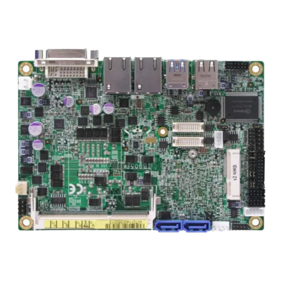
Page 23: Cn7: Dvi-I Connector
CN5: USB3.0 Connector CN6: USB2.0 Connector CN4: Gigabit LAN (Intel 82579LM) CN3: Gigabit LAN (Intel 82583V) J5: Mini-PCIE Connector CN1, CN2: SATA Connectors JP12: LPC Debug Connector (Factory use only) JP1: SPI Flash Connector (Factory use only) IB905 User’s Manual... -
Page 24: Bios Setup
The topics covered in this chapter are as follows: BIOS Introduction ................21 BIOS Setup ..................21 Main BIOS Setup ................22 Advanced Settings ................23 Chipset Settings ................. 36 Boot Settings ..................42 Security Settings ................43 Save & Exit Settings ................44 IB905 User’s Manual... -
Page 25: Bios Introduction
<PgUp> and <PgDn> keys to change entries, <F1> for help and <Esc> to quit. When you enter the Setup utility, the Main Menu screen will appear on the screen. The Main Menu allows you to select from various setup functions and exit choices. IB905 User’s Manual... -
Page 26: Main Bios Setup
System Language Choose the system default language. System Date Set the Date. Use Tab to switch between Data elements. System Time Set the Time. Use Tab to switch between Data elements. IB905 User’s Manual... -
Page 27: Advanced Settings
F4: Save & EXIT ►Sandybridge DTS Configuration ESC: Exit ►Sandybridge PPM Configuration Launch PXE OpROM Enable or Disable Boot Option for Legacy Network Devices. Launch Storage OpROM Enable or Disable Boot Option for Legacy Mass Storage Devices with Option ROM. IB905 User’s Manual... - Page 28 Enables or Disables VGA Palette Registers Snooping. PERR# Generation Enables or Disables PCI Device to Generate PERR#. SERR# Generation Enables or Disables PCI Device to Generate SERR#. Relaxed Ordering Enables or Disables PCI Express Device Relaxed Ordering. IB905 User’s Manual...
- Page 29 BIOS to select the value. ASPM Support Set the ASPM Level: Force L0- Force all links to L0 Stage: AUTO – BIOS auto configure: DISABLE- Disables ASPM. Extended Synch If ENABLED allows generation of Extended Synchronization patterns. IB905 User’s Manual...
- Page 30 OS. ACPI Sleep State Select the highest ACPI sleep state the system will enter, when the SUSPEND button is pressed. Lock Legacy Resources Enables or Disables System Lock of Legacy Resources. IB905 User’s Manual...
- Page 31 Enables or Disables System wake on alarm event. When enabled, System will wake on the hr::min:: sec specified. Wake on Ring The options are Disabled and Enabled. Wake on PCIE Wake Event The options are Disabled and Enabled. IB905 User’s Manual...
- Page 32 XD can prevent certain classes of malicious buffer overflow attacks when combined with a supporting OS (Windows Server 2003 SP1, Windows XP SP2, SuSE Linux 9.2, RedHat Enterprise 3 Update 3.) Hardware Prefetcher To turn on/off the MLC streamer prefetcher. IB905 User’s Manual...
- Page 33 F3: Optimized Default Serial ATA Port 4 Empty F4: Save & Exit Software Preserve Unknown Serial ATA Port 5 Empty ESC: Exit Software Preserve Unknown SATA Mode Determines how SATA controllers(s) operate. The options are IDE, AHCI and RAID. IB905 User’s Manual...
- Page 34 Auto Legacy USB Support Enables Legacy USB support. AUTO option disables legacy support if no USB devices are connected. DISABLE option will keep USB devices available only for EFI applications. USB3.0 Support Enable/Disable USB3.0 (XHCI) Controller support. IB905 User’s Manual...
- Page 35 Maximum time the device will take before it properly reports itself to the Host Controller. ‘Auto’ uses default value: for a Root port it is 100 ms, for a hub port the delay is taken from Hub Descriptor. IB905 User’s Manual...
- Page 36 ESC: Exit Serial Port Configuration Set Parameters of Serial Ports. User can Enable/Disable the serial port and Select an optimal settings for the Super IO Device. Power Failure Options are: Keep last state Always on Always off (default) IB905 User’s Manual...
- Page 37 PC health status. Smart Fan Mode Configuration This field enables (55C/60C/65C/70C) or disables the smart fan feature. At a certain temperature, the fan starts turning. Once the temperature drops to a certain level, it stops turning again. IB905 User’s Manual...
- Page 38 Boot Security Save & Exit → ← Select Screen Sadybridge DTS Configuration ↑↓ Select Item CPU DTS Enabled Enter: Select Change Field F1: General Help F2: Previous Values F3: Optimized Default F4: Save & Exit ESC: Exit IB905 User’s Manual...
- Page 39 Turbo Mode Turbo Mode. CPU C3 Report Enable/Disable CPU C3 (ACPI C2) report to OS. CPU C6 Report Enable/Disable CPU C6 (ACPI C3) report to OS. CPU C7 Report Enable/Disable CPU C7 (ACPI C3) report to OS. IB905 User’s Manual...
-
Page 40: Chipset Settings
→ ← Select Screen ↑↓ Select Item ► Graphics Configuration Enter: Select Change Field F1: General Help F2: Previous Values F3: Optimized Default F4: Save & Exit ESC: Exit VT-d Check to enable VT-d function on MCH. IB905 User’s Manual... - Page 41 Select DVMT 5.0 Pre-Allocated (Fixed) Graphics Memory size used by the Internal Graphics Device: 0M~512M. DVMT Total Gfx Mem Select DVMT5.0 Total Graphic Memory size used by the Internal Graphics Device: 128M, 256M, MAX. Gfx Low Power Mode This option is applicable for SFF only. IB905 User’s Manual...
- Page 42 Select LCD panel used by Internal Graphics Device by selecting the appropriate setup item: 640x480 LVDS ~ 2048x1536 LVDS. SDVO-LFP Panel Type Select SDVO panel used by Internal Graphics Device by selecting the appropriate setup item: VBIOS Default, 1024x768 ~ 1600x1200. IB905 User’s Manual...
- Page 43 Change Field High Precision Timer Enabled F1: General Help F2: Previous Values SLP_S4 Assertion Width 4-5 Seconds F3: Optimized Default Set NAND Management Override Enabled F4: Save & Exit ESC: Exit ► USB Configuration ► PCI Express Configuration IB905 User’s Manual...
- Page 44 USB Configuration Aptio Setup Utility Advanced Main Chipset Boot Security Save & Exit EHCI1 Enabled EHCI2 Enabled USB Ports Per-Port Disable Control Disabled EHCI1 Control the USB EHCI (USB2.0) functions. One EHCI controller must always be enabled. IB905 User’s Manual...
- Page 45 DMI Clink ASPM Control The control of Active State Power Management on both NB side and SB side of the DMI Link. DMI Link Extended Synch Control The control of Extended Synch on SB side of the DMI Link. IB905 User’s Manual...
-
Page 46: Boot Settings
RT code is executed above 1MB. Option ROM Messages Set display mode for Option ROM. Options are Force BIOS and Keep Current. Interrupt 19 Capture Enable: Allows Option ROMs to trap Int 19. Boot Option Priorities Sets the system boot order. IB905 User’s Manual... -
Page 47: Security Settings
Setup. In Setup the User will have Change Field Administrator rights F1: General Help F2: Previous Values Administrator Password F3: Optimized Default User Password F4: Save & Exit ESC: Exit Administrator Password Set Setup Administrator Password. User Password Set User Password. IB905 User’s Manual... -
Page 48: Save & Exit Settings
Reset system setup without saving any changes. Save Changes Save Changes done so far to any of the setup options. Discard Changes Discard Changes done so far to any of the setup options. Restore Defaults Restore/Load Defaults values for all the setup options. IB905 User’s Manual... - Page 49 Restore the User Defaults to all the setup options. Boot Override Pressing ENTER causes the system to enter the OS. Launch EFI Shell from filesystem device Attempts to Launch EFI Shell application (Shellx64.efi) from one of the available filesystem devices. IB905 User’s Manual...
-
Page 50: Drivers Installation
Realtek HD Audio Driver Installation ........49 LAN Drivers Installation ............50 ASMedia USB 3.0 Drivers ............52 IMPORTANT NOTE: After installing your Windows operating system, you must install first the Intel Chipset Software Installation Utility before proceeding with the drivers installation. IB905 User’s Manual... -
Page 51: Intel Chipset Software Installation Utility
4. Click Yes to accept the software license agreement and proceed with the installation process. 5. On the Readme File Information screen, click Next to continue the installation. 6. The Setup process is now complete. Click Finish to restart the computer and for changes to take effect. IB905 User’s Manual... -
Page 52: Vga Drivers Installation
5. On the Readme File Information screen, click Next to continue the installation of the Intel® Graphics Media Accelerator Driver. 6. On Setup Progress screen, click Next to continue. 7. Setup complete. Click Finish to restart the computer and for changes to take effect. IB905 User’s Manual... -
Page 53: Realtek Hd Audio Driver Installation
1. Insert the CD that comes with the board. Click Intel and then Intel(R) QM67/Q67 Chipset Drivers. 2. Click Realtek High Definition Audio Driver. 3. On the Welcome to the InstallShield Wizard screen, click Yes to proceed with and complete the installation process. IB905 User’s Manual... -
Page 54: Lan Drivers Installation
3. When the Welcome screen appears, click Next. On the next screen, click Yes to to agree with the license agreement. 4. Click the checkbox for Drivers in the Setup Options screen to select it and click Next to continue. IB905 User’s Manual... - Page 55 DRIVERS INSTALLATION 5. The wizard is ready to begin installation. Click Install to begin the installation. 6. When InstallShield Wizard is complete, click Finish. IB905 User’s Manual...
-
Page 56: Asmedia Usb 3.0 Drivers
1. Insert the CD that comes with the board. Click Intel and then Intel(R) QM67/Q67 Chipset Drivers. 2. Click Intel(R) PRO LAN Network Driver. 2. When the Welcome screen to the InstallShield Wizard for Intel® Management Engine Components, click Next. 3. When InstallShield Wizard is complete, click Finish. IB905 User’s Manual... - Page 57 DRIVERS INSTALLATION This page is intentionally left blank. IB905 User’s Manual...
-
Page 58: Appendix
Clear Math Coprocessor Busy Signal 0F1h Reset Math Coprocessor E000-E01F Network Connection F060-F07F Network Connection F080-F0D7 SATA Storage Controller 2F8h - 2FFh Serial Port #2(COM2) 3B0h- 3BBh Graphics adapter Controller 3F8h - 3FFh Serial Port #1(COM1) 3D0h - 3DFh CGA adapter IB905 User’s Manual... -
Page 59: Interrupt Request Lines (Irq)
Serial Port #1 IRQ5 Reserved IRQ6 Reserved IRQ7 Reserved IRQ8 Real Time Clock IRQ9 Reserved IRQ10 Serial Port #3 IRQ11 Serial Port #4 IRQ12 PS/2 Mouse IRQ13 80287 IRQ14 Primary IDE IRQ15 Secondary IDE IRQ19 SATA Storage IB905 User’s Manual... -
Page 60: Watchdog Timer Configuration
(argc != 2) printf(" Parameter incorrect!!\n"); return 1; if (Init_W627DHG() == 0) printf(" Winbond 83627HF is not detected, program abort.\n"); return 1; bTime = strtol (argv[1], endptr, 10); printf("System will reset after %d seconds\n", bTime); EnableWDT(bTime); return 0; //=========================================================================== IB905 User’s Manual... - Page 61 = Get_W627DHG_Reg( 0xF5); bBuf &= (!0x08); Set_W627DHG_Reg( 0xF5, bBuf); //count mode is second Set_W627DHG_Reg( 0xF6, interval); //set timer //=========================================================================== void DisableWDT(void) Set_W627DHG_LD(0x08); //switch to logic device 8 Set_W627DHG_Reg(0xF6, 0x00); //clear watchdog timer Set_W627DHG_Reg(0x30, 0x00); //watchdog disabled //=========================================================================== IB905 User’s Manual...
- Page 62 Init_Finish; W627DHG_BASE = 0x00; result = W627DHG_BASE; Init_Finish: return (result); //=========================================================================== void Unlock_W627DHG (void) outportb(W627DHG_INDEX_PORT, W627DHG_UNLOCK); outportb(W627DHG_INDEX_PORT, W627DHG_UNLOCK); //=========================================================================== void Lock_W627DHG (void) outportb(W627DHG_INDEX_PORT, W627DHG_LOCK); //=========================================================================== void Set_W627DHG_LD( unsigned char LD) Unlock_W627DHG(); outportb(W627DHG_INDEX_PORT, W627DHG_REG_LD); outportb(W627DHG_DATA_PORT, LD); Lock_W627DHG(); IB905 User’s Manual...
- Page 63 (W627DHG_BASE) #define W627DHG_DATA_PORT (W627DHG_BASE+1) //=========================================================================== #define W627DHG_REG_LD 0x07 //=========================================================================== #define W627DHG_UNLOCK 0x87 #define W627DHG_LOCK 0xAA //=========================================================================== unsigned int Init_W627DHG(void); void Set_W627DHG_LD( unsigned char); void Set_W627DHG_Reg( unsigned char, unsigned char); unsigned char Get_W627DHG_Reg( unsigned char); //=========================================================================== #endif //__W627DHG_H IB905 User’s Manual...