Table of Contents
Advertisement
Quick Links
Advertisement
Chapters
Table of Contents

Related Manuals for IBASE Technology IB100


Summary of Contents for IBASE Technology IB100
- Page 1 IB100 TI AM3517 ARM CortexTM-A8 Embedded BOARD USER’S MANUAL Version 1.0...
- Page 2 Acknowledgments TI is a registered trademark of Texas Instruments. All other product names or trademarks are properties of their respective owners. IB100 User’s Manual...
-
Page 3: Table Of Contents
Table of Contents Introduction ............1 Product Description ............. 1 Checklist ................3 IB100 Specifications ............4 Board Dimensions ............... 6 Installations ............9 Setting the Jumpers ............10 Connectors on IB100 MRS ..........16 IB100 User’s Manual... - Page 4 This page is intentionally left blank. IB100 User’s Manual...
-
Page 5: Introduction
INTRODUCTION Introduction Product Description The IB100 embedded board is based on the TI AM3517 ARM processor .TI AM3517 is a high-performance ARM Cortex-A8 with speeds up to 600 MHz. The device offers 3D graphics acceleration while also supporting numerous peripherals, including DDR2 and USB OTG PHY that are well suited for industrial applications. - Page 6 1 x Mini-PCIe (x1) slot (w/ USB support) • 10/100 Based-T Ethernet (RJ-45) connector • 12V DC-in power connector • 1 x SD card slot • 1 x USB OTG • 1 x USB host • LAN PoE support (option) • Resistive touch connector IB100 User’s Manual...
-
Page 7: Checklist
INTRODUCTION Checklist Your IB100 package should include the items listed below. • The IB100 Embedded board • This User’s Manual IB100 MRS User’s Manual... -
Page 8: Ib100 Specifications
USB OTG x 1 (mini USB B type) • COM1 RS-232 x 1 for (RJ45 connector) • LEDs light bar x 1 (2xGPIO pin control Red and Green/Daughter Board) (LED x12) • SD slot x 1 • 12V DC-IN Jack with lock x 1 IB100 User’s Manual... - Page 9 Audio pin Header x2 (Mic x1 /Speaker x1) • FPC connector for Touch x1 (CSF-0591-4P1T) Slots: • Half-Mini PCIe(x1) slot [USB] 26.8mm x 30 mm 12V DC-IN or PoE Power VESA 75x75 Mounting Wall mount Software Android Linux Support WinCE 0℃-45℃ Environment IB100 MRS User’s Manual...
-
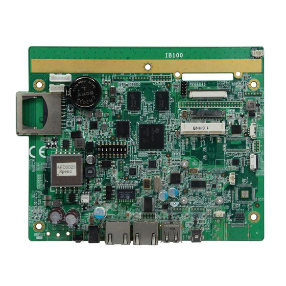
Page 10: Board Dimensions
INTRODUCTION Board Dimensions Top Side IB100 User’s Manual... - Page 11 INTRODUCTION Bottom Side IB100 MRS User’s Manual...
- Page 12 INSTALLATIONS This page is intentionally left blank. IB100 User’s Manual...
-
Page 13: Installations
INSTALLATIONS Installations This section provides information on how to use the jumpers and connectors on the IB100 in order to set up a workable system. The topics covered are: Setting the Jumpers ..............10 Connectors on IB100 MRS ............16... -
Page 14: Setting The Jumpers
INSTALLATIONS Setting the Jumpers Jumpers are used on IB100 to select various settings and features according to your needs and applications. Contact your supplier if you have doubts about the best configuration for your needs. The following lists the connectors on IB100 and their respective functions. -
Page 15: Jumper Locations On Ib100
INSTALLATIONS Jumper Locations on IB100 Top Side IB100 MRS User’s Manual... - Page 16 INSTALLATIONS Bottom Side IB100 User’s Manual...
-
Page 17: J13: Com1 Rs232 (Rj45) Pin8 /+5V/+3V Power Setting
Pin 3-5 COM1 PORT PIN 3 Short/Closed Pin 7-9 COM1 PORT PIN 3 Short/Closed COM2_RX Note: Pin 3 maximum output current is 0.5A. Default setting is Pin 1-3 Open, Pin 5-7 Open, and Pin 7-9 Open IB100 MRS User’s Manual... -
Page 18: J14: Cn6 Id Pin Control (Factory Use Only)
Note: Default is Pin 1-2 open. S1 (sw1,sw2,sw3,sw4,sw5,sw6): System Boot Configuration First Second Third Fourth (sw1 .. sw6) NAND 000100 flash 100100 COM3 NAND 111110 COM 3 flash Note: 1: Switch On 0: Switch Off Default setting is 111110 (sw1=1,sw2=1,sw3=1,sw4=1,sw5=1,sw6=0) IB100 User’s Manual... -
Page 19: S1 (Sw8): Dvi Signal Output Control
High: green color indicator dark Note: D8,D9, ..D19 are double color LED indicator, which have red and green colors. ALL of them are parallel connected together. U4 is TCA6416PAW IC; The IC connects with AM3517 CPU via I2C2 port. IB100 MRS User’s Manual... -
Page 20: Connectors On Ib100 Mrs
INSTALLATIONS Connectors on IB100 MRS Connector Locations on IB100 ............17 CN2: SD Card Connector ..............18 COM1 Port: RJ45 10 Pin Connector ........... 18 COM2 Port: COM2 RS232 Connector ..........18 COM3 Port: COM3 RS232 Connector, Debug Port Connector ..19 LVDS1: LVDS Display Connector ............. -
Page 21: Connector Locations On Ib100
INSTALLATIONS Connector Locations on IB100 IB100 MRS User’s Manual... -
Page 22: Cn2: Sd Card Connector
Note: Please refer to J13 setting for Pin3 and Pin8. COM2 Port: COM2 RS232 Connector Pin # Signal Name COM2 RTS, Request to send COM2 TXD, Transmit data COM2 RXD, Receive data COM2 CTS, Clear to send GND, ground IB100 User’s Manual... -
Page 23: Com3 Port: Com3 Rs232 Connector, Debug Port Connector
GND, ground LVDS1: LVDS Display Connector Pin # Signal Name +3.3V +3.3V TX0- TX0+ TX1- TX1+ TX2- TX2+ TXC- TXC+ +5V or +12V +5V or +12V BACKLIGHT ADJ Note: Pin 17and Pin18 default setting voltage are +5V. IB100 MRS User’s Manual... -
Page 24: Cn1: Lcd 18 Bit Parallel Signal Connector
INSTALLATIONS CN1: LCD 18 Bit Parallel Signal Connector Pin # Signal Name BACKLIGHT ADJ +3.3V +3.3V MODE VSYNC HSYNC B5(MSB) DCLK IB100 User’s Manual... -
Page 25: J3: Lcd 24 Bit Parallel Signal Connector (Factory Use Only)
+3.3V +3.3V VSYNC HSYNC DCLK BACKLIGHT ADJ BACKLIGHT ENABLE TOUCH YP TOUCH YM TOUCH XP TOUCH XM +12V +12V CN3: Resistive Touch Panel Connector Pin # Signal Name Touch YP Touch XP Touch YM Touch XM IB100 MRS User’s Manual... -
Page 26: Cn4: 10/100Mb Lan (Poe Supported)
BACKLIGHT ENABLE Note: Pin 1 maximum output current is 0.5A CN9: I2C3 Connector Pin # Signal Name GND, ground I2C3_SDA I2C3_SCL +3.3V I2C3_INT1n I2C3_RESETn CN11: I2C2 Connector Pin # Signal Name GND, ground I2C2_SDA I2C2_SCL +3.3V I2C2_INT1n I2C2_RESETn IB100 User’s Manual... -
Page 27: Cn10: Spi1 Connector
1.4 W with 8 Ω speaker J5: Speaker Left Out Connector Pin # Signal Name SPEAKER_LEFT+ SPEAKER_LEFT- Note: The maximun output power is 2 W with 4 Ω speaker or 1.4 W with 8 Ω speaker IB100 MRS User’s Manual... -
Page 28: J1: Digital I/O 4 In/4 Out Connector
Note: All In/Out signals level are 3.3V level. SW1: Push Button for Hardware Reset J6: S-Video connector BAT1: CR2032 3V LITHIUM Battery Socket CN5: 12V Power Connector This connector supplies the system board operating voltage Pin 1 Pin 2 Pin # Signal Name +12V IB100 User’s Manual... -
Page 29: Jusb1: Usb2.0 Type A Connector
JUSB1: USB2.0 Type A Connector Pin # Signal Name J11: USB2.0 Connector Pin # Signal Name J12: USB2.0 Connector Pin # Signal Name CN6: Mini USB OTG Connector Pin # Signal Name J8: Line-out Phone-Jack Connector IB100 MRS User’s Manual... -
Page 30: J7: Dvi Connector
INSTALLATIONS J7: DVI Connector Pin # Signal Name TX2+ TX2- TX1+ TX1- TX0+ TX0- TXC+ TXC- IB100 User’s Manual... -
Page 31: Jmini1: Mini Pcie Connector
INSTALLATIONS JMINI1: Mini PCIE Connector Signal Name Pin # Pin # Signal Name +3.3V RESETn USB2.0 D- USB2.0 D+ +3.3V CN12: 5V Connector Pin # Signal Name IB100 MRS User’s Manual... - Page 32 INSTALLATIONS This page is intentionally left blank. IB100 User’s Manual...
- Page 33 APPENDIX IB100 MRS User’s Manual...