Table of Contents
Advertisement
Quick Links
Advertisement
Chapters
Table of Contents

Related Manuals for IBASE Technology IB915F


Summary of Contents for IBASE Technology IB915F
- Page 1 IB915F Intel Skylake U ® 3.5” Disk Size SBC USER’S MANUAL Version 1.2...
- Page 2 Acknowledgments AMI is a registered trademark of American Megatrends Inc. PS/2 is a trademark of International Business Machines Corporation. Intel and Intel® 6 Generation Mobile Core i MCP Processor are registered trademarks of Intel Corporation. Microsoft Windows is a registered trademark of Microsoft Corporation.
-
Page 3: Table Of Contents
Board Dimensions ............... 5 Installations .............. 6 Installing the Memory ............7 Setting the Jumpers ............. 8 Connectors on IB915F ............13 BIOS Setup ............. 24 Drivers Installation ..........44 Intel Chipset Software Installation Utility......45 VGA Drivers Installation ..........47 Realtek HD Audio Driver Installation ....... - Page 4 This page is intentionally left blank. IB915 User’s Manual...
-
Page 5: Introduction
INTRODUCTION Introduction Product Description ® Intel The IB915F is a 3.5-inch single board computer based on the Skylake U MCP processors. The IB915F platform is well suited for low-power and high-performance designs in a broad range of markets including Industrial Control & Automation, Digital Signage, Thin Client, Electronic Gaming Machines, and SMB storage appliances. -
Page 6: Checklist
INTRODUCTION Checklist Your IB915F package should include the items listed below. • The IB915F SBC • This User’s Manual • 1 DVD containing chipset drivers and flash memory utility • Optional cable kit IB75 (containing DC in power cable/PW87, COM port cable / PK1H, SATA & HDD power cable/SATA-26 and USB 2.0 cable/USB-29) -
Page 7: Ib915F Specifications
- LVDS(Thru DDI#2, via NXP PTN3460BS/F6) ® Intel I219LM GbE PHY (IB915AF-6600 & IB915AF-6300) ® Intel I219V GbE PHY (IB915F-6100 & IB915F-3955) ** Thru PCIe port # 9** ® Intel I211AT as 2 GbE ** Thru PCIe port # 10** ®... - Page 8 INTRODUCTION LPC I/O Fintek F81846AD-I (128-pin LQFP [14mm x 14 mm]) COM #1 (RS232/422/485) @ edge I/O With Fintek F81439N transceiver x 1 for jumper-less selection COM #2~COM #4 (RS232 only) [Hardware Monitor] 2 x Thermal inputs 2 x Voltage monitoring 4 in &...
-
Page 9: Board Dimensions
INTRODUCTION Board Dimensions IB915 User’s Manual... -
Page 10: Installations
INSTALLATIONS Installations This section provides information on how to use the jumpers and connectors on the IB915F in order to set up a workable system. The topics covered are: Installing the Memory ................7 Setting the Jumpers ................8 Connectors on IB915F ................. 13... -
Page 11: Installing The Memory
INSTALLATIONS Installing the Memory The IB915F board supports two DDR3L memory sockets for a maximum total memory of 16GB DDR3L memory type. Installing and Removing Memory Modules To install the DDR3L modules, locate the memory slot on the board and perform the following steps: 1. -
Page 12: Setting The Jumpers
INSTALLATIONS Setting the Jumpers Jumpers are used on IB915F to select various settings and features according to your needs and applications. Contact your supplier if you have doubts about the best configuration for your needs. The following lists the connectors on IB915F and their respective functions. -
Page 13: Jumper Locations On Ib915F
INSTALLATIONS Jumper Locations on IB915F Jumpers on IB915F Page JP1: LVDS Panel Brightness Control Selection ........10 JP2: LCD Backlight Connector ............10 JP3: USB 2.0 Pin Header ..............11 JP4: SPI Flash Connector (Factory use only) ........11 JP5: LPC debug Connector (Factory use only) ........11 J7: Clear ME .................. -
Page 14: Jp1: Lvds Panel Brightness Control Selection
INSTALLATIONS JP1: LVDS Panel Brightness Control Selection Brightness Control (PWM mode) Open 3.3V Close 5V(Default) JP2: LCD Backlight Connector Pin # Signal Name +12V Backlight Enable Brightness Control Ground IB915 User’s Manual... -
Page 15: Jp3: Usb 2.0 Pin Header
INSTALLATIONS JP3: USB 2.0 Pin Header Signal Name Pin # Pin # Signal Name Ground Ground JP4: SPI Flash Connector (Factory use only) JP5: LPC debug Connector (Factory use only) IB915 User’s Manual... -
Page 16: J7: Clear Me
INSTALLATIONS J7: Clear ME Setting Function Pin 1-2 Normal Short/Closed Pin 2-3 Clear ME Short/Closed J8: Clear CMOS Contents Setting Function Pin 1-2 Normal Short/Closed Pin 2-3 Clear CMOS Short/Closed IB915 User’s Manual... -
Page 17: Connectors On Ib915F
INSTALLATIONS Connectors on IB915F Connector Locations on IB915F ............14 CN1 / CN2: SATA3 Connector ............15 CN3: Gigabit LAN (I219) / Gigabit LAN (I211AT) ......15 CN4: eDP Connector (30 Pin) ............. 15 CN5 / CN6: USB3.0 Connector ............166 CN7: COM1 RJ50 Connector ............ -
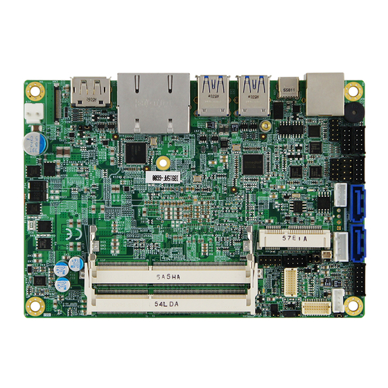
Page 18: Connector Locations On Ib915F
INSTALLATIONS Connector Locations on IB915F IB915 User’s Manual... -
Page 19: Cn1 / Cn2: Sata3 Connector
INSTALLATIONS CN1 / CN2: SATA3 Connector CN3: Gigabit LAN (I219) / Gigabit LAN (I211AT) CN4: eDP Connector (30 Pin) (I-PEX_20374-030E-31) Signal Name Pin # Pin # Signal Name BL_Power BL_Power BL_Power BL_Power BRIGHTNESS Bklt_en Panel_VDD Panel_VDD AUX_P AUX_N TX0_P TX0_N TX1_N TX1_P IB915 User’s Manual... -
Page 20: Cn5 / Cn6: Usb3.0 Connector
INSTALLATIONS CN5 / CN6: USB3.0 Connector CN7: COM1 RJ50 Connector Pin # Signal Name RJ-50_10P10C Pin # Signal Name RS-232 RS-422 RS-485 2, 3 Ground Ground Ground DATA+ DATA- CN8: DisplayPort Connector CN9: USB Type C Connector IB915 User’s Manual... -
Page 21: J1: Flash Descriptor Security Override (Factory Use Only)
INSTALLATIONS J1: Flash Descriptor Security Override (Factory use only) J2/JP6: LVDS Panel Power Selection J2/JP6 Setting Panel Voltage Pin 1-2 3.3V (default) Short/Closed Pin 2-3 Short/Closed IB915 User’s Manual... - Page 22 INSTALLATIONS J3, J4: LVDS Connectors (Hirose DF20G-20DP-1V) J4: First Channel LVDS J3: Second Channel LVDS Signal Name Pin # Pin # Signal Name TX0N TX0P Ground Ground TX1N TX1P Ground Ground TX2N TX2P Ground Ground CLKN CLKP Ground Ground TX3N TX3P Power Power...
-
Page 23: J11: Ddr3L So-Dimm (Ch-A) Socket
INSTALLATIONS J5: Audio Connector (DF11-12DP-2DSA) Signal Name Pin # Pin # Signal Name LINEOUT_R LINEOUT_L Ground JD_FRONT LINEIN_L LINEIN_R Ground JD_LINEIN MIC-R MIC_L Ground JD_MIC1 J11: DDR3L SO-DIMM (CH-A) Socket J6: DDR3L SO-DIMM (CH-B) Socket IB915 User’s Manual... -
Page 24: J9: Battery Connector
INSTALLATIONS J9: Battery Connector J10: SATA HDD Power Connectors Pin # Signal Name Ground Ground +12V J12: MCU JTAG IB915 User’s Manual... -
Page 25: J13: Mini Pcie / Msata Slot
INSTALLATIONS J13: Mini PCIE / mSATA Slot J14, J17: COM3/COM4 J15: Front Panel Signal Name Pin # Pin # Signal Name PWR_BTN 3.3V HDD Active Reset IB915 User’s Manual... -
Page 26: J16: Com2
INSTALLATIONS J16: COM2 Signal Name Pin # Pin # Signal Name DCD, Data carrier detect RXD, Receive data DTR, Data terminal ready TXD, Transmit data GND, ground DSR, Data set ready RTS, Request to send CTS, Clear to send RI, Ring indicator Not Used J18: Digital I/O Signal Name... -
Page 27: J19: Dc_In Connector
INSTALLATIONS J19: DC_IN Connector Pin # Signal Name +9V ~ +24V IB915 User’s Manual... -
Page 28: Bios Setup
BIOS SETUP BIOS Setup This chapter describes the different settings available in the BIOS that comes with the board. The topics covered in this chapter are as follows: BIOS Introduction ................25 BIOS Setup ..................25 Advanced Settings ................27 Chipset Settings ................... -
Page 29: Bios Introduction
DRIVERS INSTALLATION BIOS Introduction The BIOS (Basic Input/Output System) installed in your computer system’s ROM provides critical low-level support for a standard device such as disk drives, serial ports and parallel ports. It also adds virus and password protection as well as special support for detailed fine-tuning of the chipset controlling the entire system. -
Page 30: Bios Setup
BIOS SETUP Main Settings Aptio Setup Utility – Copyright © 2016 American Megatrends, Inc. Main Advanced Chipset Boot Security Save & Exit Choose the system default language Access Level Administrator Total memory 4096 MB → ← Memory Frequency 1600 Mhz Select Screen ↑↓... -
Page 31: Advanced Settings
DRIVERS INSTALLATION Advanced Settings This section allows you to configure and improve your system and allows you to set up some system features according to your preference. Aptio Setup Utility – Copyright © 2016 American Megatrends, Inc. Advanced Main Chipset Boot Security Save &... -
Page 32: Acpi Settings
BIOS SETUP ACPI Settings Aptio Setup Utility – Copyright © 2016 American Megatrends, Inc. Advanced Main Chipset Boot Security Save & Exit ACPI Settings → ← Select Screen Enable ACPI Auto Configuration [Disabled] ↑↓ Select Item Enter: Select Enable Hibernation [Enabled] Change Field ACPI Sleep State... -
Page 33: Panel Type
DRIVERS INSTALLATION LVDS (eDP/DP) Configuration Aptio Setup Utility – Copyright © 2016 American Megatrends, Inc. Chipset Main Advanced Boot Security Save & Exit LVDS (eDP/DP) Configuration → ← Select Screen LVDS (eDP/DP) Support [Enabled] ↑↓ Select Item Panel Color Depth [18 BIT] Enter: Select LVDS Channel Type... - Page 34 BIOS SETUP ISmart Controller Aptio Setup Utility – Copyright © 2016 American Megatrends, Inc. Advanced Main Chipset Boot Security Save & Exit ISmart Controller → ← Select Screen Power-On after Power failure [Disable] ↑↓ Select Item Temperature Guardian [Disable] Enter: Select Schedule Slot 1 [None] Change Field...
- Page 35 DRIVERS INSTALLATION AMT Configuration Aptio Setup Utility – Copyright © 2016 American Megatrends, Inc. Advanced Main Chipset Boot Security Save & Exit Intel AMT [Enabled] BIOS Hotkey Pressed [Disabled] MEBx Selection Screen [Disabled] Hide Un-Configure ME Confirmation [Disabled] → ← Amt Wait Timer Select Screen [Enabled]...
-
Page 36: Serial Port Configuration
BIOS SETUP Fintek Super IO Configuration Aptio Setup Utility – Copyright © 2016 American Megatrends, Inc. Advanced Main Chipset Boot Security Save & Exit → ← Fintek Super IO Configuration Select Screen ↑↓ Select Item Super IO Chip F81846 Serial Enter: Select ►... -
Page 37: Cpu Configuration
DRIVERS INSTALLATION CPU Configuration This section shows the CPU configuration parameters. Aptio Setup Utility – Copyright © 2016 American Megatrends, Inc. Advanced Main Chipset Boot Security Save & Exit CPU Configuration Intel(R) CPU Core(TM)i3-6100U CPU @ 2.30GHz CPU Signature 406E3 Microcode Patch Processor cores Max CPU Speed... - Page 38 BIOS SETUP Configurable TDP Boot Mode Configurable TDP Boot Mode as Nominal/Up/Down/Deactivate TDP selection. Deactivate option will set MSR to Nominal and MMIO to Zero. Configurable TDP Lock Configurable TDP Lock sets the Lock bits on TURBO_ACTIVATION_RATIO and CONFIG_TDP_CONTROL. Note: When CTDP Lock is enabled Custom ConfigTDP Count will be forced to 1 and Custom ConfigTDP Boot Index will be forced to 0.
-
Page 39: Sata Mode Selection
DRIVERS INSTALLATION SATA Configuration SATA Devices Configuration. Aptio Setup Utility – Copyright © 2016 American Megatrends, Inc. Advanced Main Chipset Boot Security Save & Exit SATA Controller(s) [Enabled] SATA Mode Selection [AHCI] ► Software Feature Mask Configuration Aggressive LPM Support [Enabled] Serial ATA Port 0 [Empty]... - Page 40 BIOS SETUP Acoustic Management Configuration Aptio Setup Utility – Copyright © 2016 American Megatrends, Inc. Advanced Main Chipset Boot Security Save & Exit → ← Acoustic Management Configuration Select Screen HDD not found ↑↓ Select Item Enter: Select Change Field F1: General Help F2: Previous Values F3: Optimized Default...
-
Page 41: Csm Configuration
DRIVERS INSTALLATION CSM Configuration Aptio Setup Utility – Copyright © 2016 American Megatrends, Inc. Boot Main Advanced Chipset Security Save & Exit Compatibility Support Module Configuration CSM Support Enabled CSM16 Module Version 07.78 GateA20 Active [Upon Request] Option ROM Messages [Force BIOS] INT19 Trap Response [Immediate]... -
Page 42: Usb Configuration
BIOS SETUP USB Configuration Aptio Setup Utility – Copyright © 2016 American Megatrends, Inc. Advanced Main Chipset Boot Security Save & Exit USB Configuration USB Module Version USB Controllers: 1 XHCI USB Devices: 1 Keyboard, 1Mouse → ← Select Screen Legacy USB Support [Enabled] ↑↓... -
Page 43: Chipset Settings
DRIVERS INSTALLATION Device power-up delay Maximum time the device will take before it properly reports itself to the Host Controller. ‘Auto’ uses default value: for a Root port it is 100ms, for a Hub port the delay is taken from Hub descriptor. Chipset Settings This section allows you to configure and improve your system and allows you to set up some system features according to your preference. -
Page 44: Wake On Lan
BIOS SETUP PCH-IO Configuration This section allows you to configure the North Bridge Chipset. Aptio Setup Utility – Copyright © 2016 American Megatrends, Inc. Chipset Main Advanced Boot Security Save & Exit Intel PCH RC Version 1.6.0.0 Intel PCH SKU Name PCH-LP Mobile (U) Pre…... -
Page 45: Security Settings
DRIVERS INSTALLATION Security Settings This section allows you to configure and improve your system and allows you to set up some system features according to your preference. Aptio Setup Utility – Copyright © 2016 American Megatrends, Inc. Security Main Advanced Chipset Boot Save &... -
Page 46: Boot Settings
BIOS SETUP Boot Settings This section allows you to configure the boot settings. Aptio Setup Utility – Copyright © 2016 American Megatrends, Inc. Boot Main Advanced Chipset Security Save & Exit Boot Configuration Setup Prompt Timeout Bootup NumLock State [On] Quiet Boot [Disabled] Fast Boot... -
Page 47: Save Changes And Exit
DRIVERS INSTALLATION Save & Exit Settings Aptio Setup Utility – Copyright © 2016 American Megatrends, Inc. Advanced Main Chipset Boot Security Save & Exit Save Changes and Exit Discard Changes and Exit Save Changes and Reset Discard Changes and Reset →... -
Page 48: Drivers Installation
DRIVERS INSTALLATION Drivers Installation This section describes the installation procedures for software and drivers. The software and drivers are included with the motherboard. If you find the items missing, please contact the vendor where you made the purchase. The contents of this section include the following: Intel Chipset Software Installation Utility ........... -
Page 49: Intel Chipset Software Installation Utility
DRIVERS INSTALLATION Intel Chipset Software Installation Utility The Intel Chipset Drivers should be installed first before the software drivers to enable Plug & Play INF support for Intel chipset components. Follow the instructions below to complete the installation. 1. Insert the DVD that comes with the board. Click Intel and then Intel(R) Skylake-U Chipset Drivers. - Page 50 DRIVERS INSTALLATION 3. When the Welcome screen to the Intel® Chipset Device Software appears, click Next to continue. 4. Click Yes to accept the software license agreement and proceed with the installation process. 5. On the Readme File Information screen, click Install to continue the installation.
-
Page 51: Vga Drivers Installation
DRIVERS INSTALLATION VGA Drivers Installation 1. Insert the DVD that comes with the board. Click Intel and then Intel(R) Skylake-U Chipset Drivers. 2. Click Intel(R) HD Graphics Driver. IB915 User’s Manual... - Page 52 DRIVERS INSTALLATION 3. When the Welcome screen appears, click Next to continue. 4. Click Yes to to agree with the license agreement and continue the installation. IB915 User’s Manual...
- Page 53 DRIVERS INSTALLATION 5. On the screen shown below, click Install to continue. 6. Setup complete. Click Finish to restart the computer and for changes to take effect. IB915 User’s Manual...
-
Page 54: Realtek Hd Audio Driver Installation
DRIVERS INSTALLATION Realtek HD Audio Driver Installation 1. Insert the DVD that comes with the board. Click Intel and then Intel(R) Skylake-U Chipset Drivers. 2. Click Realtek High Definition Audio Driver. IB915 User’s Manual... - Page 55 DRIVERS INSTALLATION 3. On the Welcome to the InstallShield Wizard screen, click Next to proceed with and complete the installation process. 4. The InstallShield Wizard Complete. Click Finish to restart the computer and for changes to take effect. IB915 User’s Manual...
-
Page 56: Lan Drivers Installation
DRIVERS INSTALLATION LAN Drivers Installation 1. Insert the DVD that comes with the board. Click Intel and then Intel(R) Skylake-U Chipset Drivers. 2. Click Intel(R) PRO LAN Network Driver. IB915 User’s Manual... - Page 57 DRIVERS INSTALLATION 3. Click Install Drivers and Software. 4. When the Welcome screen appears, click Next. IB915 User’s Manual...
- Page 58 DRIVERS INSTALLATION 5. Click Next to to agree with the license agreement. 6. Click the checkbox for Drivers in the Setup Options screen to select it and click Next to continue. 7. The wizard is ready to begin installation. Click Install to begin the installation.
-
Page 59: Intel® Management Engine Interface
DRIVERS INSTALLATION Intel® Management Engine Interface 1. Insert the DVD that comes with the board. Click Intel and then Intel(R) Skylake-U Chipset Drivers. 2. Click Intel (R) ME 11.x Drivers. IB915 User’s Manual... - Page 60 DRIVERS INSTALLATION 3. When the Welcome screen to the InstallShield Wizard for Intel® Management Engine Components, click the checkbox for Install Intel® Control Center & click Next. 4. Click Next to to agree with the license agreement. 5. When the Setup Progress screen appears, click Next. Then, click Finish when the setup progress has been successfully installed.
-
Page 61: Intel® Usb 3.0 Drivers
DRIVERS INSTALLATION Intel® USB 3.0 Drivers 1. Insert the DVD that comes with the board. Click Intel and then Intel(R) Skylake-U Chipset Drivers. 2. Click Intel(R) USB 3.0 Drivers. IB915 User’s Manual... - Page 62 DRIVERS INSTALLATION 3. When the Welcome screen to the InstallShield Wizard for Intel® USB 3.0 eXtensible Host Controller Driver, click Next. 4. Click Next to agree with the license agreement and continue the installation. IB915 User’s Manual...
- Page 63 DRIVERS INSTALLATION 5. On the Readme File Information screen, click Next to continue the installation of the Intel® USB 3.0 eXtensible Host Controller Driver. 6. Setup complete. Click Finish to restart the computer and for changes to take effect. IB915 User’s Manual...
-
Page 64: Asmedia Usb 3.1 Drivers
DRIVERS INSTALLATION ASMedia USB 3.1 Drivers 1. Insert the DVD that comes with the board. Click Intel and then Intel(R) Skylake-U Chipset Drivers. 2. Click ASMedia USB 3.1 Drivers. IB915 User’s Manual... - Page 65 DRIVERS INSTALLATION 3. When the Welcome screen to the InstallShield Wizard for Asmedia USB Host Controller Driver, click Next. 4. Setup complete. Click Finish IB915 User’s Manual...
-
Page 66: Appendix
APPENDIX Appendix A. I/O Port Address Map Each peripheral device in the system is assigned a set of I/O port addresses which also becomes the identity of the device. The following table lists the I/O port addresses used. Address Device Description 0000h-0CF7h PCI Express Root Complex 0040h-0043h... -
Page 67: Interrupt Request Lines (Irq)
APPENDIX B. Interrupt Request Lines (IRQ) Peripheral devices use interrupt request lines to notify CPU for the service required. The following table shows the IRQ used by the devices on board. Level Function IRQ0 System Timer IRQ1 Keyboard Fintek Communications Port(COM2) IRQ3 IRQ4 Fintek Communications Port(COM1) -
Page 68: Watchdog Timer Configuration
APPENDIX C. Watchdog Timer Configuration The WDT is used to generate a variety of output signals after a user programmable count. The WDT is suitable for use in the prevention of system lock-up, such as when software becomes trapped in a deadlock. Under these sorts of circumstances, the timer will count to zero and the selected outputs will be driven. - Page 69 APPENDIX //--------------------------------------------------------------------------- void EnableWDT(int interval) unsigned char bBuf; bBuf = Get_F81866_Reg(0x2B); bBuf &= (~0x20); Set_F81866_Reg(0x2B, bBuf); //Enable WDTO Set_F81866_LD(0x07); //switch to logic device 7 Set_F81866_Reg(0x30, 0x01); //enable timer bBuf = Get_F81866_Reg(0xF5); bBuf &= (~0x0F); bBuf |= 0x52; Set_F81866_Reg(0xF5, bBuf); //count mode is second Set_F81866_Reg(0xF6, interval);...
- Page 70 APPENDIX //--------------------------------------------------------------------------- // THIS CODE AND INFORMATION IS PROVIDED "AS IS" WITHOUT WARRANTY OF ANY // KIND, EITHER EXPRESSED OR IMPLIED, INCLUDING BUT NOT LIMITED TO THE // IMPLIED WARRANTIES OF MERCHANTABILITY AND/OR FITNESS FOR A PARTICULAR // PURPOSE. //--------------------------------------------------------------------------- #include "F81866.H"...
- Page 71 APPENDIX unsigned char Get_F81866_Reg(unsigned char REG) unsigned char Result; Unlock_F81866(); outportb(F81866_INDEX_PORT, REG); Result = inportb(F81866_DATA_PORT); Lock_F81866(); return Result; //--------------------------------------------------------------------------- //--------------------------------------------------------------------------- // THIS CODE AND INFORMATION IS PROVIDED "AS IS" WITHOUT WARRANTY OF ANY // KIND, EITHER EXPRESSED OR IMPLIED, INCLUDING BUT NOT LIMITED TO THE // IMPLIED WARRANTIES OF MERCHANTABILITY AND/OR FITNESS FOR A PARTICULAR // PURPOSE.