Table of Contents
Advertisement
Quick Links
Our company network supports you worldwide with offices in Germany, Austria,
Switzerland, Great Britain and the USA. For more information please contact:
FORTEC Elektronik AG
Hauptniederlassung
Lechwiesenstr. 9
86899 Landsberg am Lech
Telefon:
+49 (0) 8191 91172-0
Telefax:
+49 (0) 8191 21770
E-Mail:
sales@fortecag.de
Internet:
www.fortecag.de
FORTEC Elektronik AG
Büro Wien
Nuschinggasse 12
A-1230 Wien
Telefon:
+43 1 8673492-0
Telefax:
+43 1 8673492-26
E-Mail:
office@fortec.at
Internet:
www.fortec.at
The information contained in this document has been carefully researched and is, to the best
of our knowledge, accurate. However, we assume no liability for any product failures or
damages, immediate or consequential, resulting from the use of the information provided
herein. Our products are not intended for use in systems in which failures of product could
result in personal injury. All trademarks mentioned herein are property of their respective
owners. All specifications are subject to change without notice.
Manual
IB908
iBASE
FORTEC Elektronik AG
Büro West
Hohenstaufenring 55
50674 Köln
Telefon:
Telefax:
E-Mail:
Internet:
ALTRAC AG
(Tochter der FORTEC):
Bahnhofstraße 3
CH-5436 Würenlos
Telefon:
Telefax:
E-Mail:
Internet:
+49 (0) 221 272 273-0
+49 (0) 221 272 273-10
west@fortecag.de
www.fortecag.de
+41 (0) 44 7446111
+41 (0) 44 7446161
info@altrac.ch
www.altrac.ch
Advertisement
Chapters
Table of Contents

Related Manuals for IBASE Technology IB908F


Summary of Contents for IBASE Technology IB908F
- Page 1 Manual IB908 iBASE Our company network supports you worldwide with offices in Germany, Austria, Switzerland, Great Britain and the USA. For more information please contact: FORTEC Elektronik AG FORTEC Elektronik AG Hauptniederlassung Büro West Lechwiesenstr. 9 Hohenstaufenring 55 86899 Landsberg am Lech 50674 Köln Telefon: +49 (0) 8191 91172-0...
- Page 2 IB908F Intel Haswell-ULT ® 3.5” Disk Size SBC USER’S MANUAL Version 1.1...
- Page 3 MCP Processor are registered trademarks of Intel Corporation. Microsoft Windows is a registered trademark of Microsoft Corporation. NUVOTON is a registered trademark of NUVOTON Technology Corporation. All other product names or trademarks are properties of their respective owners. IB908F User’s Manual...
-
Page 4: Table Of Contents
IB908F Specifications ............2 Board Dimensions ............... 4 Installations ............5 Installing the Memory ............6 Setting the Jumpers ............. 7 Connectors on IB908F ............11 BIOS Setup ............23 Drivers Installation ........49 Intel Chipset Software Installation Utility ......50 VGA Drivers Installation .......... - Page 5 This page is intentionally left blank. IB908F User’s Manual...
-
Page 6: Introduction
INTRODUCTION Introduction Product Description ® Intel The IB908F is a 3.5-inch single board computer based on the Haswell-ULT MCP processors. The IB908F platform is well-suited for low-power and high-performance designs in a broad range of markets including Industrial Control &... -
Page 7: Checklist
INTRODUCTION Checklist Your IB908F package should include the items listed below. The IB908F SBC This User’s Manual 1 CD containing chipset drivers and flash memory utility Optional cable kit (containing DC in power cable/PW87, COM port cable / PK1H, SATA & HDD power cable/SATA-26 and USB 2.0 cable/USB-29) - Page 8 +9V ~ +24V DC-in Power Input RoHS 102mm x 147mm Board Size Windows 8 / Embedded; Windows 7 / Embedded Linux OS supported Heatsink Others i-SMART (Auto-scheduler & Power fail resume function) EEPROM 24C02(Reserved for designing, M-SO8 package) IB908F User’s Manual...
-
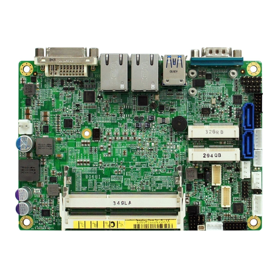
Page 9: Board Dimensions
INTRODUCTION Board Dimensions IB908F User’s Manual... -
Page 10: Installations
INSTALLATIONS Installations This section provides information on how to use the jumpers and connectors on the IB908F in order to set up a workable system. The topics covered are: Installing the Memory ................6 Setting the Jumpers ................7 Connectors on IB908F ................. 11... -
Page 11: Installing The Memory
INSTALLATIONS Installing the Memory The IB908F board supports TWO DDR3L memory socket for a maximum total memory of 16GB DDR3L memory type. Installing and Removing Memory Modules To install the DDR3L modules, locate the memory slot on the board and perform the following steps: 1. -
Page 12: Setting The Jumpers
INSTALLATIONS Setting the Jumpers Jumpers are used on IB908F to select various settings and features according to your needs and applications. Contact your supplier if you have doubts about the best configuration for your needs. The following lists the connectors on IB908F and their respective functions. -
Page 13: Jumper Locations On Ib908F
INSTALLATIONS Jumper Locations on IB908F Jumpers on IB908F ................Page J3: Clear CMOS Contents ..............9 J4: Clear ME Contents ................9 J9: LVDS Panel Power Selection ............10 IB908F User’s Manual... -
Page 14: J3: Clear Cmos Contents
INSTALLATIONS J3: Clear CMOS Contents Setting Function Pin 1-2 Normal Short/Closed Pin 2-3 Clear CMOS Short/Closed J4: Clear ME Contents Setting Function Pin 1-2 Normal Short/Closed Pin 2-3 Clear ME RTC Short/Closed REGISTER IB908F User’s Manual... -
Page 15: J7: Flash Descriptor Security Override (Factory Use Only)
INSTALLATIONS J7: Flash Descriptor Security Override (Factory use only) Flash Descriptor Security Override Open Disabled (Default) Close Enabled J9: LVDS Panel Power Selection Setting Panel Voltage Pin 1-2 3.3V (default) Short/Closed Pin 2-3 Short/Closed IB908F User’s Manual... -
Page 16: Connectors On Ib908F
INSTALLATIONS Connectors on IB908F Connector Locations on IB908F ............12 CN3, CN4: Gigabit LAN ..............13 CN3: Intel® Clarkville I218V/I218LM GbE PHY ....... 13 CN4: Intel® Pearsonville I211AT as 2nd GbE ........13 CN5: USB 1/2 Connector ..............13 CN6: VGA DVI-I Connector ............... 13 CN7: DB9 Connector ................ -
Page 17: Connector Locations On Ib908F
INSTALLATIONS Connector Locations on IB908F IB908F User’s Manual... -
Page 18: Cn3, Cn4: Gigabit Lan
DTR, Data terminal ready RI, Ring indicator GND, ground Not Used COM1 is jumper-less for RS-232, RS-422 and RS-485 and is to be configured with BIOS Selection. Pin # Signal Name RS-232 R2-422 RS-485 DATA- DATA+ Ground Ground Ground IB908F User’s Manual... -
Page 19: Cn1, Cn2: Sata Connectors
INSTALLATIONS CN1, CN2: SATA Connectors JP1: LCD Backlight Connector Pin # Signal Name +12V Backlight Enable Brightness Control Ground JP2: USB3/4 Connector Signal Name Pin # Pin # Signal Name Ground Ground IB908F User’s Manual... -
Page 20: J2: Audio Connector (Df11 Connector)
(LVDS1) and second channel (LVDS2). Signal Name Pin # Pin # Signal Name TX0N TX0P Ground Ground TX1N TX1P Ground Ground TX2N TX2P Ground Ground CLKN CLKP Ground Ground TX3N TX3P Power Power IB908F User’s Manual... -
Page 21: Jp4: Spi Flash Connector (Factory Use Only)
INSTALLATIONS JP4: SPI Flash Connector (factory use only) J5: Amplifier Connector Pin # Signal Name OUTL+ OUTL- OUTR- OUTR+ J6, J8: DDR3L SO-DIMM Sockets J7: Factory use only IB908F User’s Manual... -
Page 22: Jp6: Sata Hdd Power Connectors
INSTALLATIONS JP6: SATA HDD Power Connectors Pin # Signal Name Ground Ground +12V JP7: Debug 80 Port Connector (factory use only) J11: MCU Flash Connector (factory use only) IB908F User’s Manual... -
Page 23: J12: Smart Battery
INSTALLATIONS J12: Smart Battery Pin # Signal Name RST# ICHSWI# Ground SMB_DATA SMB_CLK J13: Board Input Power Connector Pin # Signal Name +9V to +24V IB908F User’s Manual... -
Page 24: J14: Front Panel Connector
Hard Disk Drive LED Connector: Pins 5 and 6 This connector connects to the hard drive activity LED on control panel. This LED will flash when the HDD is being accessed. Pin # Signal Name LED(+) LED(-) IB908F User’s Manual... -
Page 25: J15: Mini Pcie Connector (Supports Msata)
Pin # Pin # Signal Name DCD, Data carrier detect RXD, Receive data TXD, Transmit data Data terminal ready GND, ground DSR, Data set ready RTS, Request to send CTS, Clear to send RI, Ring indicator Not Used IB908F User’s Manual... -
Page 26: J19: Digital I/O Connector
INSTALLATIONS J19: Digital I/O Connector Signal Name Pin # Pin # Signal Name OUT3 OUT1 OUT2 OUT0 CPU_FAN1: CPU Fan Power Connector Pin # Signal Name Ground +12V Rotation detection Control IB908F User’s Manual... - Page 27 INSTALLATIONS This page is intentionally left blank. IB908F User’s Manual...
-
Page 28: Bios Setup
The topics covered in this chapter are as follows: BIOS Introduction ................24 BIOS Setup ..................24 Advanced Settings ................26 Chipset Settings ................... 39 Boot Settings..................45 Security Settings .................. 47 Save & Exit Settings ................48 IB908F User’s Manual... -
Page 29: Bios Introduction
<PgUp> and <PgDn> keys to change entries, <F1> for help and <Esc> to quit. When you enter the Setup utility, the Main Menu screen will appear on the screen. The Main Menu allows you to select from various setup functions and exit choices. IB908F User’s Manual... -
Page 30: System Date
F2: Previous Values Access Level Administrator F3: Optimized Default F4: Save ESC: Exit System Date Set the Date. Use Tab to switch between Data elements. System Time Set the Time. Use Tab to switch between Data elements. IB908F User’s Manual... -
Page 31: Advanced Settings
Value to be programmed into PCI Latency Timer Register. VGA Palette Snoop Enables or disables VGA Palette Registers Snooping. PERR# Generation Enables or disables PCI device to generate PERR#. SERR# Generation Enables or disables PCI device to generate SERR#. IB908F User’s Manual... -
Page 32: Pci Express Settings
BIOS to select the value. ASPM Support Set the ASPM Level: Force L0s – Force all links to L0s State: AUTO – BIOS auto configure: DISABLE – Disables ASPM. Extended Synch If ENABLED allows generation of Extended Synchronization patterns. IB908F User’s Manual... - Page 33 On non-PCI Express aware OS’s (Pre Windows Vista) some devices may not be correctly reinitialized after S3.Enabling this restore PCI Express device configuration on S3 resume Warning: Enabling this may cause issues with other hardware after S3 resume.1 IB908F User’s Manual...
-
Page 34: Acpi Settings
OS. ACPI Sleep State Select ACPI sleep state the system will enter, when the SUSPEND button is pressed. Lock Legacy Resources Enabled or Disabled Lock of Legacy Resources. S3 Video Repost Enable or disable S3 Video Repost. IB908F User’s Manual... - Page 35 Disabled → ← Select Screen ↑↓ Select Item Enter: Select Change Field F1: General Help F2: Previous Values F3: Optimized Default F4: Save ESC: Exit Wake on PCIE PME Wake Event The options are Disabled and Enabled. IB908F User’s Manual...
-
Page 36: Cpu Configuration
CPU AES Enabled F4: Save ESC: Exit EIST Enabled Hyper-threading Select the performance state that the BIOS will set before OS handoff. Active Processor Cores Number of cores to enable in each processor package. Overclocking lock Flex_RATIO(194)MSR IB908F User’s Manual... - Page 37 XD can prevent certain classes of malicious buffer overflow attacks when combined with a supporting OS Intel Virtualization Technology When enabled, a VMM can utilize the additional hardware capabilities provided by Vanderpool Technology. CPU AES Enabled/Disabled CPU Advanced Encryption Standard instructions EIST Enabled/Disabled Intel Speedstep. IB908F User’s Manual...
-
Page 38: Sata Configuration
Hot Plug Disabled F2: Previous Values F3: Optimized Default F4: Save ESC: Exit SATA Controller(s) Enable / Disable Serial ATA Controller. SATA Mode Selection (1) AHCI Mode. (2) RAID Mode. Hot Plug Designates this port as Hot P;uggable. IB908F User’s Manual... -
Page 39: Acpi Shutdown Temperature
Schedule Slot 2 None Change Field F1: General Help F2: Previous Values F3: Optimized Default F4: Save ESC: Exit Power-On after Power failure Enable or Disable. Schedule Slot 1 / 2 Setup the hour/minute for system power on. IB908F User’s Manual... - Page 40 Perform AMT/ME unconfigure without password operation. Amt Wait Timer Set timer to wait before sending ASF_GET_BOOT_OPTIONS. Activate Remote Assistance Process Trigger CIRA boot. PET Progress User can Enable/Disable PET Events progress to receive PET events or not. Watchdog Timer Enable/Disable Watchdog Timer. IB908F User’s Manual...
- Page 41 Maximum time the device will take before it properly reports itself to the Host Controller. ‘Auto’ uses default value: for a Root port it is 100ms, for a Hub port the delay is taken from Hub descriptor. IB908F User’s Manual...
-
Page 42: Serial Port Configuration
F1: General Help F2: Previous Values F3: Optimized Default F4: Save ESC: Exit Serial Port Configuration Set parameters of serial ports. User can Enable/Disable the serial port and Select an optimal settings for the Super IO Device. IB908F User’s Manual... -
Page 43: Smart Fan Function
Temperatures/Voltages These fields are the parameters of the hardware monitoring function feature of the board. The values are read-only values as monitored by the system and show the PC health status. IB908F User’s Manual... -
Page 44: Chipset Settings
Wake on LAN Enable or disable integrated LAN to wake the system. (The Wake On LAN cannot be disabled if ME is on at Sx state.) SLP_S4 Assertion Width Select a minimum assertion width of the SLP_S4# signal. IB908F User’s Manual... -
Page 45: Pci Express Configuration
Enable or disable PCI Express Clock Gating for each root port DMI Link ASPM Control The control of Active State Power Management on both NB side and SB side of the DMI link. PCIe-USB Glitch W/A PCIe-USB Glitch W/A for bad USB device(s) connected behind PCIE/PEG port. IB908F User’s Manual... -
Page 46: Xhci Mode
Disabled = Azalia will be unconditionally be disabled. Enabled = Azalia will be unconditionally be enabled. Auto = Azalia will be enabled if present, disabled otherwise. Azalia PME Enable or disable power management capability of the audio controller. IB908F User’s Manual... -
Page 47: Graphics Configuration
F1: General Help DVMT Total Gfx Mem 256MB F2: Previous Values ► LCD Control F3: Optimized Default F4: Save ESC: Exit Primary Display Select which of IGFX/PEG/PCI graphics device should be primary display or select SG for switchable Gfx. IB908F User’s Manual... - Page 48 Select the Video Device that will be activated during POST. This has no effect if external graphics present. Secondary booty display selection will appear based on your selection. VGA modes will be supported only on primary display. IB908F User’s Manual...
-
Page 49: Lcd Control
Int-LVDS: VBIOS enables LVDS driver by Integrated encoder. SDVO LVDS: VBIOS enables LVDS driver by SDVO encoder. eDP Port-A: LFP Driven by Int-DisplayPort encoder from Port-A. Panel Color Depth Select the LFP Panel Color Depth: 18 Bit, 24 Bit. IB908F User’s Manual... -
Page 50: Boot Settings
Enables/Disables Quiet Boot option. Fast Boot Enables/Disables boot with initialization of a minimal set of devices required to launch active boot option. Has no effect for BBS boot options. Boot Option Priorities Sets the system boot order. IB908F User’s Manual... -
Page 51: Csm Parameters
Controls the execution of UEFI and Legacy Storage OpROM. Launch Video OpROM policy Controls the execution of UEFI and Legacy Video OpROM. Other PCI device ROM priority For PCI devices other than Network, Mass storage or Video defines which OpROM to launch. IB908F User’s Manual... -
Page 52: Security Settings
↑↓ Select Item Minimum length Enter: Select Maximum length Change Field F1: General Help Administrator Password F2: Previous Values User Password F3: Optimized Default F4: Save ESC: Exit Administrator Password Set Setup Administrator Password. User Password Set User Password. IB908F User’s Manual... -
Page 53: Save & Exit Settings
Discard Changes done so far to any of the setup options. Restore Defaults Restore/Load Defaults values for all the setup options. Save as User Defaults Save the changes done so far as User Defaults. Restore User Defaults Restore the User Defaults to all the setup options. IB908F User’s Manual... -
Page 54: Drivers Installation
LAN Drivers Installation ..............58 Intel® Management Engine Interface ..........62 Intel® USB 3.0 Drivers ............... 65 IMPORTANT NOTE: After installing your Windows operating system, you must install first the Intel Chipset Software Installation Utility before proceeding with the drivers installation. IB908F User’s Manual... -
Page 55: Intel Chipset Software Installation Utility
Plug & Play INF support for Intel chipset components. Follow the instructions below to complete the installation. 1. Insert the DVD that comes with the board. Click Intel and then Intel(R) 8 Series Chipset Drivers. 2. Click Intel(R) Chipset Software Installation Utility. IB908F User’s Manual... - Page 56 DRIVERS INSTALLATION 3. When the Welcome screen to the Intel® Chipset Device Software appears, click Next to continue. 4. Click Yes to accept the software license agreement and proceed with the installation process. IB908F User’s Manual...
- Page 57 DRIVERS INSTALLATION 5. On the Readme File Information screen, click Next to continue the installation. 6. The Setup process is now complete. Click Finish to restart the computer and for changes to take effect. IB908F User’s Manual...
-
Page 58: Vga Drivers Installation
DRIVERS INSTALLATION VGA Drivers Installation 1. Insert the DVD that comes with the board. Click Intel and then Intel(R) 8 Series Chipset Drivers. 2. Click Intel(R) Core(TM) i3/i5/i7 Graphics Driver. IB908F User’s Manual... - Page 59 DRIVERS INSTALLATION 3. When the Welcome screen appears, click Next to continue. 4. Click Yes to to agree with the license agreement and continue the installation. IB908F User’s Manual...
- Page 60 DRIVERS INSTALLATION 5. On the screen shown below, click Install to continue. 6. Setup complete. Click Finish to restart the computer and for changes to take effect. IB908F User’s Manual...
-
Page 61: Realtek Hd Audio Driver Installation
DRIVERS INSTALLATION Realtek HD Audio Driver Installation 1. Insert the DVD that comes with the board. Click Intel and then Intel(R) 8 Series Chipset Drivers. 2. Click Realtek High Definition Audio Driver. IB908F User’s Manual... - Page 62 DRIVERS INSTALLATION 3. On the Welcome to the InstallShield Wizard screen, click Yes to proceed with and complete the installation process. 4. The InstallShield Wizard Complete. Click Finish to restart the computer and for changes to take effect. IB908F User’s Manual...
-
Page 63: Lan Drivers Installation
DRIVERS INSTALLATION LAN Drivers Installation 1. Insert the DVD that comes with the board. Click Intel and then Intel(R) 8 Series Chipset Drivers. 2. Click Intel(R) PRO LAN Network Driver. IB908F User’s Manual... - Page 64 DRIVERS INSTALLATION 3. Click Install Drivers and Software. 4. When the Welcome screen appears, click Next. IB908F User’s Manual...
- Page 65 DRIVERS INSTALLATION 5. Click Next to to agree with the license agreement. 6. Click the checkbox for Drivers in the Setup Options screen to select it and click Next to continue. IB908F User’s Manual...
- Page 66 DRIVERS INSTALLATION 7. The wizard is ready to begin installation. Click Install to begin the installation. 8. When InstallShield Wizard is complete, click Finish. IB908F User’s Manual...
-
Page 67: Intel® Management Engine Interface
DRIVERS INSTALLATION Intel® Management Engine Interface 1. Insert the DVD that comes with the board. Click Intel and then Intel(R) 8 Series Chipset Drivers and then Intel(R) AMT 9.5 Drivers. IB908F User’s Manual... - Page 68 DRIVERS INSTALLATION 2. When the Welcome screen to the InstallShield Wizard for Intel® Management Engine Components, click the checkbox for Install Intel® Control Center & click Next. 3. Click Yes to to agree with the license agreement. IB908F User’s Manual...
- Page 69 DRIVERS INSTALLATION 4. When the Setup Progress screen appears, click Next. Then, click Finish when the setup progress has been successfully installed. IB908F User’s Manual...
-
Page 70: Intel® Usb 3.0 Drivers
DRIVERS INSTALLATION Intel® USB 3.0 Drivers 1. Insert the DVD that comes with the board. Click Intel and then Intel(R) 8 Series Chipset Drivers. 2. Click Intel(R) USB 3.0 Drivers. IB908F User’s Manual... - Page 71 DRIVERS INSTALLATION 3. When the Welcome screen to the InstallShield Wizard for Intel® USB 3.0 eXtensible Host Controller Driver, click Next. 4. Click Yes to to agree with the license agreement and continue the installation. IB908F User’s Manual...
- Page 72 5. On the Readme File Information screen, click Next to continue the installation of the Intel® USB 3.0 eXtensible Host Controller Driver. 6. Setup complete. Click Finish to restart the computer and for changes to take effect. IB908F User’s Manual...
-
Page 73: Appendix
Interrupt Controller #2 081h - 091h DMA Controller #2 040h – 05Fh SMBus Controler 2F8h - 2FFh Serial Port #2(COM2) 3C0h- 3DFh Graphics adapter Controller D000 - FFFh PCI-e Root Ports 3F8h - 3FFh Serial Port #1(COM1) IB908F User’s Manual... -
Page 74: Interrupt Request Lines (Irq)
The following table shows the IRQ used by the devices on board. Level Function IRQ0 System Timer Output IRQ1 Keyboard IRQ3 Serial Port #2 IRQ4 Serial Port #1 IRQ8 Real Time Clock IRQ10 SMBus Controller IRQ19 SATA AHCI Controller IB908F User’s Manual... -
Page 75: Watchdog Timer Configuration
**endptr; char SIO; printf("6106 watch dog program\n"); bTime = strtol (argv[1], endptr, 10); printf("System will reset after %d seconds\n", bTime); if (bTime) else if (bTime > 0 && bTime < 256) A=2; unsigned char result; Set_6106_LD(0x08); gotoxy(1,12); IB908F User’s Manual... - Page 76 = 6106_BASE; ucDid = Get_6106_Reg(0x20); if (ucDid == 0x07) //6106 goto Init_Finish; 6106_BASE = 0x2E; result = 6106_BASE; ucDid = Get_6106_Reg(0x20); if (ucDid == 0x07) //6106 goto Init_Finish; 6106_BASE = 0x00; result = 6106_BASE; Init_Finish: return (result); IB908F User’s Manual...
- Page 77 LD); Lock_6106(); //--------------------------------------------------------------------------- void Set_6106_Reg( unsigned char REG, unsigned char DATA) Unlock_6106(); outportb(6106_INDEX_PORT, REG); outportb(6106_DATA_PORT, DATA); Lock_6106(); //--------------------------------------------------------------------------- unsigned char Get_6106_Reg(unsigned char REG) unsigned char Result; Unlock_6106(); outportb(6106_INDEX_PORT, REG); Result = inportb(6106_DATA_PORT); Lock_6106(); return Result; //------------------------------------------------------------------------------------ IB908F User’s Manual...
- Page 78 Our company network supports you worldwide with offices in Germany, Austria, Switzerland, Great Britain and the USA. For more information please contact: FORTEC Elektronik AG FORTEC Elektronik AG Hauptniederlassung Büro West Lechwiesenstr. 9 Hohenstaufenring 55 86899 Landsberg am Lech 50674 Köln Telefon: +49 (0) 8191 91172-0 Telefon:...