Crestron 3 Series Operation Manual
Hide thumbs
Also See for 3 Series:
- Reference manual (68 pages) ,
- Operation manual (48 pages) ,
- Supplemental manual (22 pages)
Table of Contents
Advertisement
Quick Links
Advertisement
Table of Contents

Related Manuals for Crestron 3 Series


Summary of Contents for Crestron 3 Series
- Page 1 Crestron AV3 & PRO3 3-Series Control Systems Operations Guide...
- Page 2 SD-3C, LLC in the United States and/or other countries. Other trademarks, registered trademarks, and trade names may be used in this document to refer to either the entities claiming the marks and names or their products. Crestron disclaims any proprietary interest in the marks and names of others.
-
Page 3: Table Of Contents
Reference Documents ....................45 Further Inquiries ......................45 Future Updates ......................45 Return and Warranty Policies ....................46 Merchandise Returns / Repair Service ..............46 Crestron Limited Warranty ..................46 Operations Guide – DOC. 7330C 3-Series Control Systems: AV3 & PRO3 • i... -
Page 5: 3-Series Control Systems: Av3 & Pro3
• High speed USB 2.0 host port ® • Industry standard Ethernet and Cresnet wired communications • Control Subnet — provides a dedicated local network for Crestron devices ® • Onboard e-Control Webserver • Supports Core 3 UI™ XPanel Web-based remote control ®... - Page 6 • Three built-in 3-Series™ control card expansion slots ® • Native BACnet /IP support • Installer setup via front panel, Crestron Toolbox™ or Internet ® Explorer (PRO3 only) • Backward compatible to run existing SIMPL programs • Full Unicode (multi-language) support •...
- Page 7 Remote access is simplified using the myCrestron Dynamic DNS service to establish a friendly URL for the home system. If technical support is ever needed, a Crestron system installer can even perform diagnostics and implement updates to the system remotely without coming on site.
- Page 8 3-Series Control Systems Crestron AV3 & PRO3 Cresnet Cresnet provides a dependable network wiring solution for Crestron keypads, lighting controls, thermostats, and other devices that don’t require the higher speed of Ethernet. The Cresnet bus offers easy wiring and configuration, carrying bidirectional communication and 24 Vdc power to each device over a simple 4-conductor cable.
-
Page 9: Specifications
SNMP; BACnet/IP; IPv4 or IPv6; Active Directory authentication; IIS v.6.0 WebServer; SMTP e-mail client; installer setup via Crestron Toolbox or Microsoft Internet Explorer; supports all e-Control, Core 3 UI XPanel, Crestron Mobile, and ® Crestron Fusion™ and RoomView applications Control Subnet... - Page 10 Devices IR Learner CSP-LIR-USB Remote Asset Management Software Fusion RV IR Emitter Probe IRP2 Dynamic DNS Service for Crestron systems myCrestron PoE Injector PWE-4803RU Remote Help Desk and Resource RoomView Express Management Software 6 • 3-Series Control Systems: AV3 & PRO3...
-
Page 11: Physical Description
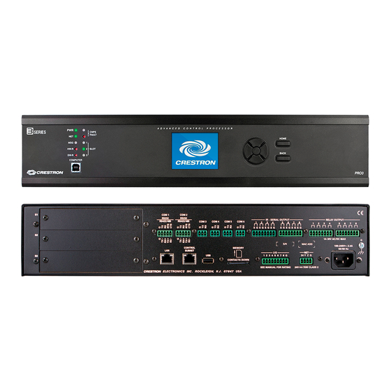
Crestron AV3 & PRO3 3-Series Control Systems Physical Description This section provides information on the connections, controls and indicators available on the AV3 and PRO3. AV3 Physical View (Front View) AV3 Physical View (Rear View) PRO3 Physical View (Front View) PRO3 Physical View (Rear View) Operations Guide –... - Page 12 3-Series Control Systems Crestron AV3 & PRO3 AV3 & PRO3 Overall Dimensions (Front View, PRO3 shown) 1.75 in 3.47 in (45 mm) (89 mm) 0.86 in (22mm) 18.31 in (465 mm) 19.00 in (483 mm) AV3 & PRO3 Overall Dimensions (Rear View, PRO3 shown)
- Page 13 Crestron AV3 & PRO3 3-Series Control Systems AV3 & PRO3 Overall Dimensions (Top View, PRO3 shown) 17.16 in (436 mm) 9.78 in 10.06 in (249 mm) (256 mm) 0.25 in (7 mm) 17.28 in (439 mm) Connectors, Controls & Indicators...
- Page 14 Crestron Studio™ or SIMPL Windows; Blinking indicates card is installed, but is either not communicating with processor or not included in AV3/PRO3 Crestron Studio or SIMPL Windows program BACK Button (1) push button, steps menu back one level COM (1 –...
- Page 15 Crestron AV3 & PRO3 3-Series Control Systems Connectors, Controls & Indicators (Continued) CONNECTORS DESCRIPTION CONTROLS & INDICATORS IR - SERIAL (2) 8-pin 3.5 mm detachable terminal blocks OUTPUT (1 – 8) comprising (8) IR/Serial output ports; IR output up to 1.2 MHz;...
- Page 16 3-Series Control Systems Crestron AV3 & PRO3 Connectors, Controls & Indicators (Continued) CONNECTORS DESCRIPTION CONTROLS & INDICATORS (1) USB Type A female; USB 2.0 port for storage devices MEMORY (1) Memory card slot; Accepts up to 32 GB for memory expansion (SD memory card not included) I/O (1 –...
-
Page 17: Setup
“Master” control system on the Cresnet network and cannot be changed. IP ID The IP ID is set within the AV3 or PRO3’s IP table using Crestron Toolbox. For information on setting an IP table, refer to the Crestron Toolbox help file. -
Page 18: Installation
3-Series Control Systems Crestron AV3 & PRO3 Installation NOTE: If power needs to be removed from this product, the power cord must be disconnected; therefore, the outlet must be installed near the equipment and must be easily accessible. Ventilation The AV3 and PRO3 should be used in a well-ventilated area. The venting holes should not be obstructed under any circumstances. - Page 19 3-Series Control Systems To install the ears, use the following procedure. CAUTION: To prevent equipment damage, use only the rack ears Crestron provides for this device. There are screws that secure each side of the AV3 and PRO3 top cover.
-
Page 20: Hardware Hookup
Apply power after all connections have been made. When making connections to the AV3 and PRO3, note the following: • Use Crestron power supplies for Crestron equipment. • The included cables cannot be extended. Hardware Connections for the AV3 & PRO3 (Front Panel)