Crestron 3 Series Operation Manual
Hide thumbs
Also See for 3 Series:
- Reference manual (68 pages) ,
- Supplemental manual (22 pages) ,
- Operation manual (20 pages)
Table of Contents
Advertisement
Quick Links
Advertisement
Table of Contents

Related Manuals for Crestron 3 Series


Summary of Contents for Crestron 3 Series
- Page 1 Crestron MC3 3-Series Control System™ Operations Guide...
- Page 2 This document was prepared and written by the Technical Documentation department at: Crestron Electronics, Inc. 15 Volvo Drive Rockleigh, NJ 07647 1-888-CRESTRON Important Safety Instructions • Read these instructions. WARNING: • Keep these instructions. TO REDUCE THE RISK OF FIRE OR ELECTRIC SHOCK, •...
- Page 3 Crestron, the Crestron logo, 3-Series Control System, Cameo, Cresnet, Crestron e-Control, Crestron Mobile, Crestron Toolbox, D3 Pro, Fusion RV, infiNET EX, Isys, SIMPL+ and SystemBuilder are trademarks or registered trademarks of Crestron Electronics, Inc. in the United States and other countries. Apple, iPad, iPhone and Mac are trademarks of Apple Inc., registered in the U.S. and other countries. EMerge Alliance and the EMerge Alliance logo are either trademarks or registered trademarks of Emerge Alliance Corporation in the United States and/or other countries.
-
Page 5: Table Of Contents
Installation ......................... 15 Hardware Hookup ..................... 15 Programming Software ......................17 Earliest Version Software Requirements for the PC ..........17 Programming with Crestron SystemBuilder.............. 17 Programming with D3 Pro..................17 Programming with SIMPL Windows ................ 18 Uploading and Upgrading......................19 Establishing Communication.................. -
Page 7: 3-Series Control System™: Mc3
• Built-in IR, COM, relay, and digital input ports • High-speed USB 2.0 host ports • ® Installer setup via Crestron Toolbox™ or Internet Explorer (Continued on following page) ® ® * Web-based installer setup requires the Microsoft Internet Explorer ®... - Page 8 LAN, WAN, and the Internet. Today, our many Crestron e-Control solutions offer more ways than ever to control your world the way you want. With Crestron e-Control, you can control anything in your home from anywhere in ® the world using a Crestron touch screen, a Windows or Mac computer, or even the 2 •...
- Page 9 IR Wireless Option When equipped with the optional CNXRMIRD IR Receiver*, the MC3 affords a low-cost IR wireless control solution using any Crestron IR wireless remote or touch screen, such as the TPS-6X*, or a third-party universal IR remote. Sold separately.
-
Page 10: Applications
3-Series Control System™ Crestron MC3 Applications The following diagram shows a MC3 in a residential application. MC3 in a Residential Application 4 • 3-Series Control System™: MC3 Operations Guide – DOC. 7095D... -
Page 11: Specifications
10/100 Mbps, auto-switching, auto- negotiating, auto-discovery, full/half duplex; industry-standard TCP/IP stack, UDP/IP, CIP, DHCP, SSL, IPv4 or IPv6, IIS v.6.0 Web Server, SMTP e-mail client, installer setup via Crestron Toolbox or MSIE, ® supports all Crestron e-Control 2, Crestron ®... - Page 12 3-Series Control System™ Crestron MC3 MC3 Specifications (Continued) SPECIFICATION DETAILS Video Reserved for future applications Audio Functions Audio file playback, audio signal pass through with mute during file playback, global volume and mute control Audio File Formats WAV (8 & 16 bit PCM, mono & stereo, 8 –...
- Page 13 1. Consult the specifications for each wireless network device to verify wireless capabilities and limitations. 2. The latest software versions can be obtained from the Crestron Web site. Refer to the NOTE following these footnotes. NOTE: Crestron software and any files on the Web site are for authorized Crestron dealers and Crestron Authorized Independent Programmers (CAIPs) only.
-
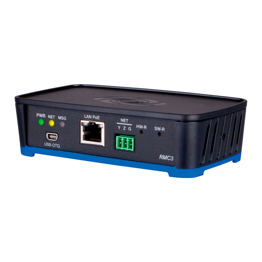
Page 14: Physical Description
3-Series Control System™ Crestron MC3 Physical Description This section provides information on the connections, controls and indicators available on your MC3. MC3 Physical View (Front View) MC3 Physical View (Rear View) 8 • 3-Series Control System™: MC3 Operations Guide – DOC. 7095D... - Page 15 Crestron MC3 3-Series Control System™ MC3 Overall Dimensions (Top View) 8.00 in (204 mm) 5.34 in 5.10 in (136 mm) (130 mm) 1.39 in (35 mm) 0.38 in (10 mm) 8.12 in (207 mm) MC3 Overall Dimensions (Side View) 3-Series Control System™: MC3 • 9...
- Page 16 3-Series Control System™ Crestron MC3 MC3 (Front View) MC3 (Rear View) Connectors, Controls & Indicators CONNECTORS DESCRIPTION CONTROLS & INDICATORS COMPUTER (1) USB Type B female USB 2.0 computer console port 6 ft (2 m) cable included DESCRIPTION +5 VDC...
- Page 17 (5) 3.5 mm mini-phone jacks, IR/Serial output ports; IR output up to 1.2 MHz; 1-way serial TTL/RS-232 (0-5 Volts) up to 115.2k baud Use Crestron Infrared Emitter Probe (model STIRP, sold separately) for controlling infrared devices. For information on other serial control cables, contact Crestron. Ring...
- Page 18 Output Impedance: 75 Ω nominal IR IN (1) 3.5 mm TRS mini-phone jack; For connection of the CNXRMIRD IR receiver Allows IR wireless control from Crestron and third-party remotes using RC-5 IR commands. Ring Sleeve Tip: IR Data In...
- Page 19 Pin 1 is on the far left. Sold separately. The MC3 can be powered via the 24 VDC jack or the NET port. Be sure to use a Crestron approved power supply as another may cause damage.
-
Page 20: Setup
“master” control system. IP ID The IP ID is set within the MC3’s table using Crestron Toolbox™. For information on setting an IP table, refer to the Crestron Toolbox help file. NOTE: The IP ID for multiple MC3s should be the same if the MC3s need to communicate with each other. -
Page 21: Installation
Apply power after all connections have been made. When making connections to the MC3, note the following: • Use Crestron power supplies for Crestron equipment. • The included cables cannot be extended. Hardware Connections for the MC3 (Front View) 3-Series Control System™: MC3 •... - Page 22 3-Series Control System™ Crestron MC3 Hardware Connections for the MC3 (Rear View – Audio, Video and IR Connections) NOTE: Video is routed to the output selected in the program loaded on the MC3. Hardware Connections for the MC3 (Rear View – COM, LAN, Relay, Ground, Input, Power, NET and USB Connections) NOTE: Ensure the unit is properly grounded by connecting the chassis ground lug to an earth ground (building steel).
-
Page 23: Programming Software
Have a question or comment about Crestron software? Answers to frequently asked questions (FAQs) can be viewed in the Online Help section of the Crestron Web site. To post a question or view questions you have submitted to Crestron’s True Blue Support, log in at www.crestron.com/support. -
Page 24: Programming With Simpl Windows
It is organized into two separate but equally important “Managers”: Configuration and Program. Configuration Manager Configuration Manager is the view where programmers “build” a Crestron control system by selecting hardware from the Device Library. To incorporate the MC3 as the “master” control system, drag the MC3 from the Control Systems folder of the Device Library and drop it in the System Views. -
Page 25: Uploading And Upgrading
The COMPUTER port on the MC3 connects to the USB port on the PC via the included Type A to Type B USB cable: 1. Use the Address Book in Crestron Toolbox to create an entry using the expected communication protocol (USB). When multiple USB devices are connected, identify the MC3 by entering “MC3”... -
Page 26: Programs And Firmware
The MC3 connects to PC via Ethernet: 1. Establish USB communication between MC3 and PC. 2. Enter the IP address, IP mask and default router of the MC3 via Crestron Toolbox (Functions | Ethernet Addressing); otherwise enable DHCP. NOTE: Use the Device Discovery Tool in Crestron Toolbox to detect all Ethernet devices on the network and their IP configuration. - Page 27 To upload firmware to the MC3, the Package Update Tool must be used. Refer to the Crestron Toolbox help file for details. Upgrade the MC3 firmware via the Package Update Tool in Crestron Toolbox. 1. Establish communication with the MC3 and display the “System Info”...
-
Page 28: Operation
Before setting up the MC3 the time and time zone needs to be configured. Use the Crestron Toolbox to connect to the MC3, refer to “Establishing Communication” on page 19 for additional details. Select Functions | System Clock… and make the appropriate changes. - Page 29 Crestron MC3 3-Series Control System™ The “MC3 Setup” screen displays the IP address, hostname and MAC address of the device. It also allows access to various setup and programming screens. The main screen of the MC3 setup utility contains buttons for Ethernet Setup, Audio Setup, Video Setup, Application Setup, Input/Output Control, Diagnostics, and About, as shown in the illustration below.
- Page 30 3-Series Control System™ Crestron MC3 Ethernet Setup From the “MC3 Setup” screen click on Ethernet Setup to enter the “Ethernet Setup” screen. This page allows toggling of the DHCP server (default is off), as shown in the illustration below. “Ethernet Setup” Screen Advanced Settings Select the Advanced Settings button from the “Ethernet Setup”...
- Page 31 NOTE: Changing the CIP Port to something other than 41794 will result in disabling access to this setup program from a Web browser. In order to re-enable it, you will need to use Crestron Toolbox to connect to the control system, and set the CIP Port back to 41794.
- Page 32 Tests can be run on the MC3 to verify connections. Click the Ping Default Router button to ping the router. To verify external communications you may ping the Crestron Web site by clicking the Ping Crestron.com button. “Ethernet Diagnostics” Screen 26 •...
- Page 33 Click the Who button to display a list of devices that are connected to the PC via the Ethernet connection. These devices may be Crestron Ethernet devices, third party Ethernet devices and PCs (including any PC using Crestron Toolbox to connect to the processor over Ethernet).
- Page 34 3-Series Control System™ Crestron MC3 “Audio” Screen The Mute On button will mute all audio coming from the MC3 to the audio device. The Mute Off button allows the audio to go to the audio device. Press the icon to return to the previous page.
- Page 35 Crestron MC3 3-Series Control System™ The video resolution must be properly set in order for the display device to view it correctly. Select an appropriate resolution for the connected display. Press the icon to return to the previous page. Application Setup Click the Application Setup button from the “MC3 Setup”...
- Page 36 3-Series Control System™ Crestron MC3 “Application Setup | IP Table” Screen Press the icon to return to the previous page. Application Setup - Details Click Details to view specific source and program information of a program. The “Application Setup | Details” screen permits a detailed view of the program. Use the up or down arrow to scroll through the menu.
- Page 37 Crestron MC3 3-Series Control System™ Input/Output Control Click Input/Output Control from the “MC3 Setup” screen to open the “I/O Control” screen. The MC3 allows control over a wide array of devices which may require specific communication settings. Use this screen to configure the control settings.
- Page 38 3-Series Control System™ Crestron MC3 “Diagnostics” Screen The MC3 stores and displays vital system information that can be referred to when troubleshooting the device or performing diagnostics on the system. Click Show Message Log to display events that have been stored by the MC3. The Show Last Reboot Message displays the final message stored before the device was reset.
-
Page 39: Acquiring Infinet Ex Devices
Each device must have an RF channel assignment that matches the RF channel assignment of the gateway. Crestron infiNET EX devices can communicate with a MC3 only if they have been acquired by that MC3. The Acquire mode can be activated from Crestron Toolbox (recommended) or with the ACQUIRE button on the MC3. - Page 40 38 and “Appendix B: Optimum RF Reception Guidelines” on page 40. Establish communication with the MC3 (refer to “Establishing Communication” which starts on page 19), use Crestron Toolbox to set the operating channel. Set the RF channel by selecting Functions | MC3… in Crestron Toolbox. Refer to the Crestron Toolbox Help file for more details.
-
Page 41: Problem Solving
Crestron MC3 3-Series Control System™ Problem Solving Troubleshooting The following table provides corrective action for possible trouble situations. If further assistance is required, please contact a Crestron customer service representative. MC3 Troubleshooting TROUBLE POSSIBLE CAUSE(S) CORRECTIVE ACTION Device does not... -
Page 42: Check Network Wiring
Cresnet power usage of the entire chain. If the unit is home-run from a Crestron system power supply network port, the Cresnet power usage of that unit is the Cresnet power usage of the entire run. The wire gauge and the Cresnet power usage of the run should be used in the following equation to calculate the cable length value on the equation’s left side. -
Page 43: Reference Documents
Crestron Web site (www.crestron.com) for a listing of Crestron worldwide offices. You can also log onto the online help section of the Crestron Web site (www.crestron.com/onlinehelp) to ask questions about Crestron products. First-time users will need to establish a user account to fully benefit from all available features. -
Page 44: Appendix A: The Rf Spectrum
3-Series Control System™ Crestron MC3 Appendix A: The RF Spectrum Crestron’s RF network provides 16 RF channels in the 2.4GHz ISM* band, specifically IEEE 802.15.4 channels 11 through 26. The 16 channels define the frequencies at which the RF device will communicate. -
Page 45: Appendix B: Optimum Rf Reception Guidelines
(no obstructions between gateway and receiver). Crestron recommends that the gateway is at least five to six feet high for best results. Avoid placing transceivers or transmitters at a low height or on the ground. - Page 46 3-Series Control System™ Crestron MC3 Horizontal Orientation Building Antenna Vertical Orientation Right Angle Orientation 40 • 3-Series Control System™: MC3 Operations Guide – DOC. 7095D...
-
Page 47: Return And Warranty Policies
Crestron software, including without limitation, product development software and product operating system software is licensed to Crestron dealers and Crestron Authorized Independent Programmers (CAIPs) under a limited non-exclusive, non-transferable license pursuant to a separate end-user license agreement. The terms of this end user license agreement can be found on the Crestron Web site at www.crestron.com/legal/software_license_agreement. - Page 48 Crestron Electronics, Inc. Operations Guide – DOC. 7095D 15 Volvo Drive Rockleigh, NJ 07647 (2028877) Tel: 888.CRESTRON 12.11 Fax: 201.767.7576 Specifications subject to www.crestron.com change without notice.