Table of Contents
Advertisement
Model No. WESY29521
Serial No.
Write the serial number in the
space above for reference.
Serial Number Decal (under seat)
QUESTIONS?
As a manufacturer, we are
committed to providing com-
plete customer satisfaction. If
you have questions, or if there
are missing parts, we will guar-
antee complete satisfaction
through direct assistance from
our factory.
TO AVOID DELAYS, PLEASE
CALL DIRECT TO OUR TOLL-
FREE CUSTOMER HOT LINE.
The trained technicians on our
customer hot line will provide
immediate assistance, free of
charge to you.
CUSTOMER HOT LINE:
1-800-999-3756
Mon.–Fri., 6 a.m.–6 p.m. MST
CAUTION
Read all precautions and instruc-
tions in this manual before using
this equipment. Save this manual
for future reference.
USER'S MANUAL
Visit our website at
www.weiderfitness.com
new products, prizes,
fitness tips, and much more!
Advertisement
Table of Contents

Related Manuals for Weider WESY29521


Summary of Contents for Weider WESY29521
- Page 1 Model No. WESY29521 Serial No. Write the serial number in the space above for reference. Serial Number Decal (under seat) QUESTIONS? As a manufacturer, we are committed to providing com- plete customer satisfaction. If you have questions, or if there...
-
Page 2: Table Of Contents
Note: A PART IDENTIFICATION CHART and a PART LIST/EXPLODED DRAWING are attached in the center of this manual. Remove the PART IDENTIFICATION CHART and the PART LIST/EXPLODED DRAWING before beginning assembly. WEIDER is a registered trademark of ICON Health & Fitness, Inc. -
Page 3: Important Precautions
IMPORTANT PRECAUTIONS WARNING: To reduce the risk of serious injury, read the following important precau- tions before using the weight system. 1. Read all instructions in this manual and in the accompanying literature before using the weight system. Use the weight system only as described in this manual. -
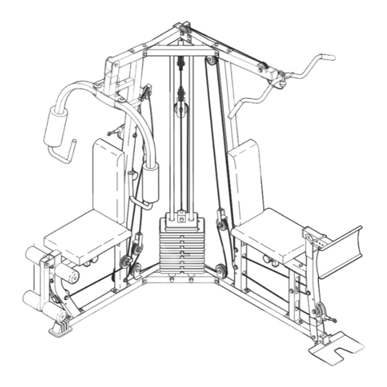
Page 4: Product View
(excluding holidays). To help us assist you, please note the product model number and serial number before calling. The model number is WESY29521. The serial number can be found on a decal attached to the weight system (see the front cover of this manual). -
Page 5: Assembly
ASSEMBLY Make Things Easier for Yourself Everything in this manual is designed to ensure that the weight system can be assembled suc- cessfully by anyone. However, it is important to realize that the versatile weight system has many parts and that the assembly process will take time. - Page 6 3. Attach the Base Plate (37) to the Left Base (2) with an M10 x 135mm Bolt (58) and an M10 Nylon Locknut (70). Be sure that the textured side is on top. Attach the Left Upright (7) to the Left Base (2) with the two indicated M10 x 65mm Carriage Bolts (57) and two M10 Nylon Locknuts (70).
- Page 7 5. Orient the Right Seat Frame (5) with the short side of the adjustment tube on top. Attach the Right Seat Frame to the Right Leg (73) with two M10 x 85mm Bolts (60), two M10 Washers (75), and two M10 Nylon Locknuts (70). Attach the Right Seat Frame (5) to the Right Upright (6) with two M10 x 85mm Bolts (60), two M10 Washers (75), and two M10 Nylon Locknuts...
- Page 8 8. Slide the eight Weights (72) onto the Weight Guides (20) with the pin grooves on the side shown. Press the Weight Tube Bumper (32) into the bot- tom of the Weight Tube (82). Insert the Weight Tube into the center hole in the stack of Weights (72).
-
Page 9: Arm Assembly
11. Press the two Weight Guide Bushings (44) into the Center Top Frame (14). Slide the Center Top Frame onto the Weight Guides (20). Attach the Center Top Frame (14) to the Right Top Frame (8) with two M10 x 70mm Bolts (81), two M10 Washers (75), and two M10 Nylon Locknuts (70). - Page 10 14. Lubricate an M10 x 80mm Button Head Bolt (97) and both sides of two Plastic Washers (55) with grease. Attach the Right Butterfly Arm (11) to the Butterfly Frame (9) with the Bolt, the two Plastic Washers, two Butterfly Caps (54), and an M10 Nylon Locknut (70).
-
Page 11: Cable Assembly
CABLE ASSEMBLY IMPORTANT: While assembling the cables, do not overtighten the locknuts attaching the pulleys; the pulleys must be able to turn freely. Refer to the CABLE DIAGRAMS and the CABLE ID CHART on pages 24 and 25 for help identifying the cables and for prop- er cable routing. - Page 12 21. Wrap the High Cable (45) around a 90mm Pulley (38). Attach the Pulley at the forward hole, inside of the bracket on the Center Top Frame (14) with an M10 x 45mm Bolt (66) and an M10 Nylon Locknut (70). 22.
- Page 13 25. Route the Leg Press Cable (95) through the Left Leg (36) and the Left Upright (7) as shown. Wrap the Cable around a 90mm Pulley (38). Attach the Pulley inside the Upright with an M10 x 70mm Bolt (81), two M10 Washers (75), two 13mm Spacers (34), and an M10 Nylon Locknut (70).
- Page 14 29. Wrap the Butterfly Cable (46) around a “V”-Pulley (39). Attach the Pulley and a Long Cable Trap (40) to the bracket on the Right Upright (6) with an M10 x 60mm Bolt (65) and an M10 Nylon Locknut (70). Be sure the Cable Trap is turned to hold the Cable in the groove of the Pulley.
- Page 15 33. Locate the Leg Lever Cable (96). Route the eyelet end of the Cable through the Right Leg (73) and attach it to the Leg Lever (4) with an M10 x 25mm Shoulder Bolt (99) and an M10 Nylon Locknut (70). 34.
- Page 16 37. Attach the end of the Leg Lever Cable (96) to the other “U”-Bracket (85) with an M8 Washer (26) and an M8 Nylon Locknut (71). Note: Do not completely tighten the Nylon Locknut; it should be threaded only two turns onto the end of the Cable, as shown in the inset draw- ing.
- Page 17 41. Wrap the Low Cable (47) around a 90mm Pulley (38). Attach the Pulley to the indicated bracket on the Left Base (2) with an M10 x 45mm Bolt (66) and an M10 Nylon Locknut (70). 42. Wrap the Low Cable (47) around a 90mm Pulley (38).
- Page 18 45. Wrap the Low Cable (47) around a 90mm Pulley (38). Attach the Pulley and a Cable Trap (91) to the indicated bracket on the Right Base (1) with an M10 x 45mm Bolt (66) and an M10 Nylon Locknut (70). Be sure the Cable Trap is turned to hold the Cable in the groove of the Pulley.
-
Page 19: Seat Assembly
SEAT ASSEMBLY 49. Press two 20mm x 40mm Inner Caps (104) and a 25mm x 40mm Inner Cap (105) into an Adjustable Seat Frame (100). Attach a Seat (16) to an Adjustable Seat Frame (100) with two M6 x 16mm Screws (13), an M6 x 33mm Screw (90), and an M6 Washer (35). -
Page 20: Adjustments
53. Insert the two Locking Pins (53) into the Butterfly Frame (9). Attach the tether on the Pins to the Butterfly Frame with an M4 x 9.5mm Self-tapping Screw (68). Do not fully tighten the Screw. 54. Make sure that all parts have been properly tightened. The use of all remaining parts will be explained in ADJUSTMENTS, starting below. - Page 21 ADJUSTING THE SEAT AND BACKREST To change the height of either Seat (16), remove the Adjustment Knob (102). Raise or lower the Seat to the desired height and re-engage the Knob. The position of the Backrest (15) on the Right Upright (6) can be adjusted in the same manner.
- Page 22 TIGHTENING THE CABLES Woven cable, the type of cable used on the weight system, can stretch slightly when it is first used. If there is slack in the cables before resistance is felt, the cables should be tightened. See drawing A. Slack can be removed by moving the 90mm Pulley (38) and Cable Trap (91) to a higher set of holes in the Adjustable Double “U”-Bracket (56).
-
Page 23: Weight Resistance Chart
ADJUSTING THE SEATS to adjust the height of a Seat (16), remove the Adjustment Knob (102) and reposition the Seat. Engage the Knob into the Left Seat Frame (29) and the Adjustable Seat Frame (100). Fully tighten the Knob. The other Seat (16) and the adjustable Backrest (not shown) can be adjusted in the same manner. -
Page 24: Cable Diagram
CABLE DIAGRAMS The cable diagrams below show the proper routing of the High Cable (45), the Butterfly Cable (46), the Low Cable (47), the Leg Press Cable (95), and the Leg Lever Cable (96). Use the diagrams to make sure that the cables and the cable traps have been assembled correctly. - Page 25 Leg Press Cable (95) Leg Lever Cable (96) CABLE ID CHART — (46) 47 3/7” — (96) 95 1/2” — (95) 148 1/4” — (47) 276 3/4” — (45) 116 3/4”...
-
Page 26: Exercise Guidelines
EXERCISE GUIDELINES THE FOUR BASIC TYPES OF WORKOUTS Muscle Building To increase the size and strength of your muscles, push them close to their maximum capacity. Your mus- cles will continually adapt and grow as you progres- sively increase the intensity of your exercise. You can adjust the intensity level of an individual exercise in two ways: •... - Page 27 Rest for a short period of time after each set. The ideal resting periods are: • Rest for three minutes after each set for a muscle building workout. • Rest for one minute after each set for a toning work- out.
- Page 28 PART IDENTIFICATION CHART—Model No. WESY29521 R1002B M5 Washer (50) M6 Washer (35) M8 Washer (26) M10 Washer (75) M10 Nylon Locknut (70) M8 Nylon Locknut (71) 19mm Round Inner Cap (27) 25mm Round Inner Cap (24) 38mm Square Inner Cap (41)
- Page 29 M10 x 50mm Bolt (62) M10 x 45mm Bolt (66) M8 x 45mm Bolt (69) M6 x 33mm Screw (90) M10 x 25mm Shoulder Bolt (99) M8 x 16mm Shoulder Bolt (78) M4 x 20mm Self-tapping Screw (77) M8 x 16mm Bolt (64) M6 x 16mm Bolt (13) M4 x 9.5mm Self-tapping Screw (68) M10 x 60mm Bolt (65)
- Page 30 PART LIST—Model No. WESY29521 Key No. Qty. Description Right Base Left Base Left Top Frame Leg Lever Right Seat Frame Right Upright Left Upright Right Top Frame Butterfly Frame Left Butterfly Arm Right Butterfly Arm Press Handle M6 x 16mm Bolt...
- Page 31 EXPLODED DRAWING—Model No. WESY29521 R1002B...
-
Page 32: Ordering Replacement Parts
Friday, 6 a.m. until 6 p.m. Mountain Time (excluding holidays). To help us assist you, please be pre- pared to give the following information: 1. The MODEL NUMBER of the product (WESY29521) 2. The NAME of the product (WEIDER 3.