Table of Contents
Advertisement
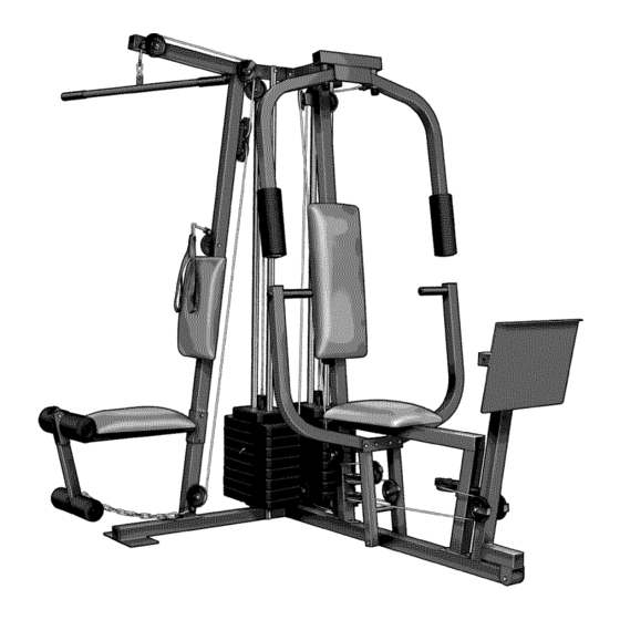
Model No. WESY26330
Serial No.
Write
the serial
number
in the space
above
for future
reference.
Serial Number Decal (Under Seat)
QUESTIONS?
As a manufacturer, we are
committed to providing complete
customer satisfaction. If you
have questions, or if there are
missing or damaged parts, we
will guarantee complete satisfac-
tion through direct assistance
from our factory.
TO AVOID UNNECESSARY
DELAYS, PLEASE CALL DIRECT
TO OUR TOLL-FREE CUSTOMER
HOT LINE. The trained techni-
cians on our customer hot line
will provide immediate assis-
tance, free of charge to you.
CUSTOMER HOT LINE:
1-800-999-3756
Mon.-Fri.,
6 a.m.-6 p.m. MST
_CAUTION
Read all precautions and instruc-
tions in this manual before using
this equipment. Save this manual
for future reference.
|
USER'S
UAL
www.weiderfitness.corn
new products,
prizes,
fitness
tips, and much
more!
Advertisement
Table of Contents

Related Manuals for Weider PRO 3750


Summary of Contents for Weider PRO 3750
- Page 1 Model No. WESY26330 Serial No. Write the serial number in the space above for future reference. USER'S Serial Number Decal (Under Seat) QUESTIONS? As a manufacturer, we are committed to providing complete customer satisfaction. If you have questions, or if there are missing or damaged parts, we will guarantee complete satisfac- tion through direct assistance...
-
Page 2: Table Of Contents
TABLE OF CONTENTS IMPORTANT PRECAUTIONS ............. BEFORE YOU BEGIN ..............ASSEMBLY ................ADJUSTMENTS ............... WEIGHT RESISTANCE CHART ............TROUBLESHOOTING AND MAINTENANCE ..........CABLE DIAGRAMS ..............ORDERING REPLACEMENT PARTS ..........Back Cover LIMITED WARRANTY ............Back Cover Note: A PART IDENTIFICATION CHART and a PART LIST/EXPLODED DRAWING are attached in the center of this manual. -
Page 3: Important Precautions
iMPORTANT PRECAUTIONS WARNING: To reduce the risk of serious injury, read the following important precautions before using the weight system. Read all instructions in this manual and in 12. Always disconnect the lat bar from the the accompanying literature before using the weight system when performing an exercise weight system,... -
Page 4: Before You Begin
BEFORE YOU BEGIN Thank you for selecting the versatile WELDER '_PRO Department toll-free at 1-800-999-3756, Monday 3750 weight system. The weight system offers a selec- through Friday, 6 a.m. until 6 p.m. Mountain Time tion of weight stations designed to develop every (excluding holidays). -
Page 5: Assembly
ASSEMBLY Make sure you have the following tools: Make Assembly Easier for Yourself • Two (2) adjustable wrenches Everything in this manual is designed to ensure that the weight system can be assem- • One (1) standard screwdriver bled successfully by anyone. Before begin- •... - Page 6 Before you begin this step, make sure that you have read all of the information on page 5. This brief introduction will save you much more time than it takes to read it. Locate and open the parts bags labeled "FRAME ASSEMBLY BAG ONE"...
- Page 7 Slide the Front Seat Frame (8) onto the indi- cated 5/16" x 2 1/2" Carriage Bolts (49) in the Press Base (13). Hand tighten two 5/16" Nylon Locknuts (40) onto the Carriage Bolts. Do not tighten the Locknuts yet. Attach the other end of the Front Seat Frame (8) to the Leg Press Upright (4) with two 5/16"...
- Page 8 Lubricate the insides of the indicated holes in the Top Weights (24). Slide a Top Weight onto each set of Weight Guides (23). Lubricate ¸I,M¸ Attach the Top Frame (2) to the Ab Upright (1) with two 5/16" x 2 3/4" Bolts (55), two 5/16" Washers (20), and two 5/16"...
- Page 9 11. Press a 1 3/4" Square Inner Cap (48) into the Adjustment Tube (10). Attach the Leg Press Plate (11) to the Adjustment Tube (10) with a 5/16" x 2 1/2" Bolt (39), two 5/16" Washers (20), and a 5/16" Nylon Locknut (40).
- Page 10 15.Attacha Press Arm(7)to onesideofthe PressFrame (12)withtwo5/16" x 2 1/2"Bolts (39)andtwo5/16"NylonLocknuts ( 40). Attach the other Press Arm (7) to the Press Frame (12) in the same manner. 16. Press a 1" Round Inner Cap (70) into one of the Press Arms (7). Press a 1 3/4" Square Inner Cap (48) into the Press Arm.
- Page 11 18. Press a 1 3/4" Square Inner Cap (48) into the lower end of the Left Fly Arm (6). Wet the lower end of the Left Fly Arm with soapy water. Slide a 10" Pad (22) onto the Left Fly Arm.
- Page 12 21. Wrap the Butterfly Cable (89) around a 3 1/2" Pulley (82) as shown. Attach the Pulley and a Cable Trap (80) to the bracket on the Leg Press Upright (4) with a 3/8" x 2" Bolt (50) and a 3/8" Nylon Locknut (42). The Cable Trap must be oriented to hold the Cable in the groove of the Pulley.
- Page 13 25. Identify the Rear Cable (87)--this is the shortest Cable. Slide the Rear Cable onto the 5/16" x 3" Bolt (92). Thread another 5/16" Nylon Jamnut (91) onto the Bolt, but do not fully tighten it. Leave enough room between the two Jamnuts for the Cable to pivot.
- Page 14 29. Identify the Press Cable (88)--this is the longest Cable. Attach the end of the Press Cable to the Large "U"-bracket (84) with a 1/4" Nylon Locknut (44) and a 1/4" Washer (37). Do not completely tighten the Locknut. It should be threaded onto the end of the Cable so only a couple of...
- Page 15 32. Route the Press Cable (88) over the indicated 3 1/2" Pulley (82) attached to the Pulley Plates (31). The Cable must be routed from the direction shown. Refer to the inset drawing. Make sure that the Press Cable (88) is between the Cable Trap (80) and the 3 1/2"...
- Page 16 36. Route the Press Cable (88) over a 3 1/2" Pulley (82). Attach the Pulley and a Cable Trap (80) to the indicated hole in the Press Frame (12) with a 3/8" x 3 1/2" Bolt (66), a 3/8" Washer (38), and the 3/8" Nylon Locknut (42).
- Page 17 40. Note: The 3 1/2" Pulley (82) used in this step was attached in step 38. It is shown removed for easier part identification. Route the Press Cable (88) around the 3 1/2" Pulley (82). Be sure that the Cable Trap (80) is turned to hold the Cable in place and that the Cable is routed as shown.
- Page 18 Locate the remaining preassembled pair of Pulley Plates (31) and 3 1/2" Pulleys (82). Route the High Cable (85) under the indicated 3 1/2" Pulley (82). The end of the Pulley Plates (31) with two holes should be down- ward. Refer to the inset drawing. Be sure that the Cable is between the Cable Trap (80) and the Pulley, and that the Cable Trap is positioned to hold the Cable in place.
- Page 19 48. Wrap the Low Cable (86) around a 3 1/2" Pulley (82). Attach the Pulley and a Cable Trap (80) to theAb Upright (1) with the 3/8" x 3 3/4" Bolt (76) and a 3/8" Nylon Locknut (42). Be sure that the Cable Trap is in the indi- cated position.
- Page 20 51. Locate and open the parts bag labeled "SEAT ASSEMBLY." Attach the Small Backrest (18) to the Ab Upright (1) with two 1/4" x 2 1/2" Machine Screws (64) and two 1/4" Washers (37). Press a 1 1/2" Square Inner Cap (57) into the Rear Seat Frame (16).
- Page 21 55. Press two 3/4" Round Inner Caps (78) into each Pad Tube (28). Insert a Pad Tube (28) into the Rear Seat Frame (16). Slide two Foam Pads (29) onto the ends of the Pad Tube. Insert the other Pad Tube (28) into the Leg Lever (15).
-
Page 22: Adjustments
ADJUSTMENTS The instructions below describe how each part of the weight system can be adjusted. Refer to the exercise guide accompanying this manual to see how the weight system should be set up for each exercise. IMPOR- TANT: When attaching the lat bar or nylon strap, make sure that the attachments are in the correct start- ing position... - Page 23 ATTACHING THE AB STRAP TO THE AB PULLEY STATION Attach the Ab Strap (35) to the Low Cable (86) at the ab pulley station with a Cable Clip (33). ATTACHING AND REMOVING THE SEAT To attach the Seat (17), set the bracket on the Rear Seat Frame (16) onto the pins on theAb Upright (1).
- Page 24 WEIGHT RESISTANCE CHART This chart shows the approximate weight resistance at each weight station. "Top" refers to the 6.5 lb. top weight. The other numbers refer to the 12.5 lb. weight plates. The butterfly arm resistance listed is the resistance for each butterfly arm.
- Page 25 TROUBLESHOOTING AND MAINTENANCE Inspect and tighten all parts each time the weight system is used. Replace any worn parts immediately. The weight system can be cleaned using a damp cloth and mild non-abrasive detergent. Do not use solvents. TIGHTENING THE CABLES Woven cable, the type of cable used on the weight system, can stretch slightly when it is first used.
-
Page 26: Cable Diagrams
CABLE DIAGRAMS The cable diagrams on this page and the next page show the proper routing of the High Cable (85), the Low Cable (86), the Rear Cable (87), the Press Cable (88), and the Butterfly Cable (89). Use the diagrams to be sure that the cables have been assembled correctly. - Page 27 High Cable (85) Rear Cable (87) 1--Top Frame High Pulley--1 4,--Weight Stack Weight Stack--5...
- Page 28 PART IDENTIFICATION CHART---Model No. WESY26330 R1103A 1/4" Washer (37) 1" Tap Screw (72) 5/16" Washer (20) 1/4" x 3/4" Screw (59) 3/8" Washer (38) 5/16" x 1" Shoulder Bolt (51) 1/4" Nylon Locknut (44) 5/16" x 1 3/4" Bolt (68) 5/16"...
- Page 29 1" Round Inner Cap (70) 1" Inner Cap (98) 1" x 7/8" PLastic Bushing (54) 1 1/8" x 2 1/2" PLastic Bushing (47) 1 1/2" Square Inner Cap (57) 1/2" x 3/4" Spacer (69) 1" Round Outer Cap (46) 3/4" Round Inner Cap (78) 1 3/4"...
- Page 30 5/16" x 2 1/2" Bolt (39) © © © 3/8" x 2 1/2" Bolt (65) 1/4" x 2 1/2" Carriage Bolt (60) 5/16" x 2 1/2" Carriage Bolt (49) 5/16" x 2 3/4" Bolt (55) 5/16" x 2 3/4" Carriage Bolt (77) 5/16"...
- Page 31 PART LISTmModel No. WESY26330 R1103A Key No. Qty. Description Key No. Qty. Description Ab Upright 5/16" x 1" Shoulder Bolt Top Frame 3/8" x 8" Bolt Butterfly Frame Leg Press Bumper Leg Press Upright 1" x 7/8" Plastic Bushing Right Fly Arm 5/16"...
- Page 32 ....895 t ..Qa o 40 42 &...
- Page 33 1. The MODEL NUMBER of the product (WESY26330) 2. The NAME of the product (WELDER _ PRO 3750 weight system) 3. The SERIAL NUMBER of the product (see the front cover of this manual) 4.