Table of Contents
Advertisement
Quick Links
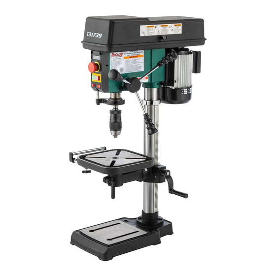
MODEL T31739
12" VARIABLE-SPEED
BENCHTOP DRILL PRESS
OWNER'S MANUAL
(For models manufactured since 11/19)
COPYRIGHT © JANUARY, 2020 BY GRIZZLY INDUSTRIAL, INC.
WARNING: NO PORTION OF THIS MANUAL MAY BE REPRODUCED IN ANY SHAPE
OR FORM WITHOUT THE WRITTEN APPROVAL OF GRIZZLY INDUSTRIAL, INC.
#CS20663 PRINTED IN CHINA
V1.01.20
Advertisement
Table of Contents

Related Manuals for Grizzly T31739


Summary of Contents for Grizzly T31739
- Page 1 (For models manufactured since 11/19) COPYRIGHT © JANUARY, 2020 BY GRIZZLY INDUSTRIAL, INC. WARNING: NO PORTION OF THIS MANUAL MAY BE REPRODUCED IN ANY SHAPE OR FORM WITHOUT THE WRITTEN APPROVAL OF GRIZZLY INDUSTRIAL, INC. #CS20663 PRINTED IN CHINA V1.01.20...
- Page 2 This manual provides critical safety instructions on the proper setup, operation, maintenance, and service of this machine/tool. Save this document, refer to it often, and use it to instruct other operators. Failure to read, understand and follow the instructions in this manual may result in fire or serious personal injury—including amputation, electrocution, or death.
-
Page 3: Table Of Contents
Table of Contents INTRODUCTION ..........2 SECTION 5: ACCESSORIES ......27 Contact Info............ 2 SECTION 6: MAINTENANCE ......28 Manual Accuracy ........... 2 Schedule ............28 Identification ........... 3 Cleaning & Protecting ........28 Controls & Components ......... 4 Lubrication ........... 28 Machine Data Sheet ........ -
Page 4: Introduction
ID label (see below). This information is required for us to provide proper tech support, and it helps us determine if updated documenta- tion is available for your machine. Manufacture Date Serial Number Model T31739 (Mfd. Since 11/19) -
Page 5: Identification
For Your Own Safety Read Instruction Manual Before Operating Drill Press a) Wear eye protection. b) Do not wear gloves, necktie, or loose clothing. c) Clamp workpiece or brace against column to prevent rotation. d) Use recommended speed for drill accessory and workpiece material. Model T31739 (Mfd. Since 11/19) -
Page 6: Controls & Components
OFF. rate from 400 to 2700 RPM. Digital Readout: Displays spindle RPM. Spindle Return Spring: Automatically returns quill into headstock. Laser ON/OFF Switch: Turns laser sights ON or OFF. Quill: Houses spindle and spindle bearings. Model T31739 (Mfd. Since 11/19) -
Page 7: Machine Data Sheet
Machine Data Sheet MACHINE DATA SHEET Customer Service #: (570) 546-9663 · To Order Call: (800) 523-4777 · Fax #: (800) 438-5901 MODEL T31739 12" VARIABLE‐SPEED BENCHTOP DRILL PRESS WITH LASER Product Dimensions: Weight................................88 lbs. Width (side-to-side) x Depth (front-to-back) x Height................13 x 22 x 36 in. - Page 8 The information contained herein is deemed accurate as of 3/4/2020 and represents our most recent product specifications. Model T31739 PAGE 2 OF 2 Due to our ongoing improvement efforts, this information may not accurately describe items previously purchased. Model T31739 (Mfd. Since 11/19)
-
Page 9: Section 1: Safety
Never operate under the influence of drugs or injury or blindness from flying particles. Everyday alcohol, when tired, or when distracted. eyeglasses are NOT approved safety glasses. Model T31739 (Mfd. Since 11/19) - Page 10 Make sure they are properly installed, you experience difficulties performing the intend- undamaged, and working correctly BEFORE ed operation, stop using the machine! Contact our operating machine. Technical Support at (570) 546-9663. Model T31739 (Mfd. Since 11/19)
-
Page 11: Additional Safety For Drill Presses
If normal safety pre- respect. Failure to do so could result in cautions are overlooked or ignored, seri- serious personal injury, damage to equip- ous personal injury may occur. ment, or poor work results. Model T31739 (Mfd. Since 11/19) -
Page 12: Section 2: Power Supply
-10- Model T31739 (Mfd. Since 11/19) - Page 13 Two-prong outlets do not meet the grounding requirements for this machine. Do not modify or use an adapter on the plug provided—if it will not fit the outlet, have a qualified electrician install the proper outlet with a verified ground. -11- Model T31739 (Mfd. Since 11/19)
-
Page 14: Section 3: Setup
IMPORTANT: Save all packaging materials until you are completely satisfied with the machine and have resolved any issues between Grizzly or the shipping agent. You MUST have the original pack- aging to file a freight claim. It is also extremely helpful if you need to return your machine later. -
Page 15: Inventory
Box 1 (Figure 5) A. Table Assembly .......... 1 Figure 5. T31739 loose parts inventory. B. Headstock Assembly ........1 C. Downfeed Handles ........3 D. Speed Lever ..........1 E. -
Page 16: Hardware Recognition Chart
Hardware Recognition Chart USE THIS CHART TO MATCH UP HARDWARE DURING THE INVENTORY AND ASSEMBLY PROCESS. Flat Head Screw -14- Model T31739 (Mfd. Since 11/19) -
Page 17: Cleanup
NOTICE Avoid harsh solvents like acetone or brake parts cleaner that may damage painted sur- faces. Always test on a small, inconspicu- ous location first. -15- Model T31739 (Mfd. Since 11/19) -
Page 18: Bench Mounting
Lift headstock and fit it onto top of column (see Figure 10). Lag Screw Flat Washer Machine Base Workbench Figure 10. Headstock placed on column. Figure 8. "Direct Mount" setup. -16- Model T31739 (Mfd. Since 11/19) - Page 19 Figure 14. Table height lock handle inserted into cartridge. Figure 12. Location of set screws that secure Install table into table mounting arm (see headstock to column. Figure 15). Table Mounting Figure 15. Table installed into table arm. -17- Model T31739 (Mfd. Since 11/19)
-
Page 20: Joining Drill Chuck & Arbor
Speed Adjustment Spindle Speed Figure 19. Tapping drill chuck/arbor on block of Lever wood. Attempt to separate drill chuck and arbor by Figure 18. Spindle speed lever installed. hand —if they separate, repeat Steps 3–4. -18- Model T31739 (Mfd. Since 11/19) -
Page 21: Test Run
— If the machine does start, immediately turn it OFF and disconnect power. The safety feature of the Emergency Stop but- ton is NOT working properly and must be replaced before further using the machine. -19- Model T31739 (Mfd. Since 11/19) -
Page 22: Section 4: Operations
Page 21. ects. Regardless of the content in this sec- tion, Grizzly Industrial will not be held liable Connects machine to power, and turns for accidents caused by lack of training. -
Page 23: Choosing Spindle Speeds
Mild Steel Carbide Insert Type One-Piece Type 1800 Tenon/Plug Cutters Soft Wood Hard Wood Plastic Brass Aluminum Mild Steel 3/8" – 1/2" 1200 1000 5/8" – 1" Figure 21. Drill bit speed chart (RPMs). -21- Model T31739 (Mfd. Since 11/19) -
Page 24: Changing Spindle Speed
Changing Spindle Installing/Removing Speed Chuck Arbor The Model T31739 has a variable-speed spin- Usually, once the chuck and arbor have been dle that operates between 400-2700 RPM. This properly mounted together, they are considered speed range is achieved using an adjustable pul- semi-permanent connections. - Page 25 Carefully retract the quill into the headstock. Figure 25. Feed return stop nut location. Move table up until it is ⁄ " below bottom of chuck, and place a towel or cloth under the chuck. -23- Model T31739 (Mfd. Since 11/19)
-
Page 26: Installing/Removing Drill Bits
Installing/Removing Adjusting Depth Stop Drill Bits The Model T31739 has a depth stop that allows you to drill repeat non-through holes to the same Any drill bit you install in the chuck must be depth every time. tight enough that it will not come loose during operation. -
Page 27: Positioning Table
Rack Table Height Table Height Lock Handle Crank Handle Pivot Lock Figure 32. Support arm extension locks. Handle Adjust support arm to desired length. Figure 30. Table adjustment controls. Tighten support arm extension locks. -25- Model T31739 (Mfd. Since 11/19) -
Page 28: Adjusting Laser Sight
ON using switch on front of drill press (see Once crosshairs are aligned with indenta- Figure 33). tion in workpiece, tighten screws loosened in Step 7 to secure laser positions. Laser ON/ OFF Switch Figure 33. Location of laser ON/OFF switch. -26- Model T31739 (Mfd. Since 11/19) -
Page 29: Section 5: Accessories
To reduce this risk, only install accessories recommended for this machine by Grizzly. NOTICE Refer to our website or latest catalog for additional recommended accessories. -
Page 30: Section 6: Maintenance
FROM POWER BEFORE PERFORMING LUBRICATION. T23962—ISO 68 Moly-D Way Oil, 5 Gal. Cleaning the Model T31739 is relatively easy. T26419—Syn-O-Gen Synthetic Grease Vacuum excess wood chips and sawdust, and wipe off the remaining dust with a dry cloth. If any... - Page 31 Quill & Column Surfaces Clean the column rack teeth in a similar manner with mineral spirits, shop rags, and a brush. Oil Type ..Grizzly T23962 or ISO 68 Equivalent Oil Amount ..........Thin Coat Lubrication Frequency ...8 Hrs. of Operation Move the spindle all the way down to access the smooth surfaces of the quill.
-
Page 32: Section 7: Service
9. Chuck or cutter at fault. 9. Replace out-of-round chuck, dull, or bent cutter. 10. Motor bearings at fault. 10. Test by rotating shaft; rotational grinding/loose shaft requires bearing replacement. -30- Model T31739 (Mfd. Since 11/19) - Page 33 2. Check for proper connections or replace (Page 36). 2. Wires disconnected or damaged. 3. Laser/LED ON/OFF switch at fault. 3. Replace switch. 4. Replace laser/LED (Page 33). 4. Laser/LED damaged/at fault. 5. Circuit board at fault. 5. Replace circuit board. -31- Model T31739 (Mfd. Since 11/19)
-
Page 34: V-Belt Tension & Replacement
3. Hold depth stop at zero, and tighten return stop nut to hold depth stop in position. Figure 46. Spindle speed lever location. 4. Test depth stop by measuring how far spindle moves with respect to where you set depth stop. -32- Model T31739 (Mfd. Since 11/19) -
Page 35: Replacing Lasers & Led Worklight
Open belt cover and identify which cord is connected to laser by lightly tugging cords fed into headstock (see Figure 49). Figure 49. Worklight and laser cords fed into headstock. -33- Model T31739 (Mfd. Since 11/19) - Page 36 Figure 51. Worklight position and clamps. light wires, and feed new worklight back through headstock and worklight hole. Replace control panel cover and close belt cover. Use spring clamps to secure worklight in position. -34- Model T31739 (Mfd. Since 11/19)
-
Page 37: Adjusting Spring Tension
— If spindle does not retract quickly, repeat ing Step 5, or force of spring will cause cover Steps 4–9, and re-check tension until to spin out of your hands. return speed is adequate. -35- Model T31739 (Mfd. Since 11/19) -
Page 38: Section 8: Wiring
Technical Support at (570) 546-9663. The photos and diagrams included in this section are best viewed in color. You can view these pages in color at www.grizzly.com. -36- Model T31739 (Mfd. Since 11/19) -
Page 39: Wiring Diagram
LAY5- Button BE102 ON/OFF Ground Ground Switch DKLD DZ04 LED LIGHT 1W 3.5V LASER LIGHT SWITCH SWITCH GORBO GORBO XCK-017 XCK-017 LASERS DKLD 1801 Figure 58. Speed sensor. READ ELECTRICAL SAFETY -37- Model T31739 (Mfd. Since 11/19) ON PAGE 36! -
Page 40: Section 9: Parts
SECTION 9: PARTS We do our best to stock replacement parts when possible, but we cannot guarantee that all parts shown are available for purchase. Call (800) 523-4777 or visit www.grizzly.com/parts to check for availability. Main 51 52 78-1 78-2... - Page 41 POLY V-BELT AX35 PT31739056 SPEED CONTROL KNOB SHAFT PT31739107 POWER CORD 18G 3W 39.5" 5-15P PT31739057 KNOB M8-1.25, D32, BALL PT31739108 LEVER BUY PARTS ONLINE AT GRIZZLY.COM! -39- Model T31739 (Mfd. Since 11/19) Scan QR code to visit our Parts Store.
-
Page 42: Labels & Cosmetics
Safety labels help reduce the risk of serious injury caused by machine hazards. If any label comes off or becomes unreadable, the owner of this machine MUST replace it in the original location before resuming operations. For replacements, contact (800) 523-4777 or www.grizzly.com. BUY PARTS ONLINE AT GRIZZLY.COM! -40- Model T31739 (Mfd. -
Page 43: Warranty & Returns
WARRANTY & RETURNS Grizzly Industrial, Inc. warrants every product it sells for a period of 1 year to the original purchaser from the date of purchase. This warranty does not apply to defects due directly or indirectly to misuse, abuse, negligence, accidents, repairs or alterations or lack of maintenance.