Table of Contents
Advertisement
Quick Links
Montage- und Betriebsanleitung
Installation and operating instruction
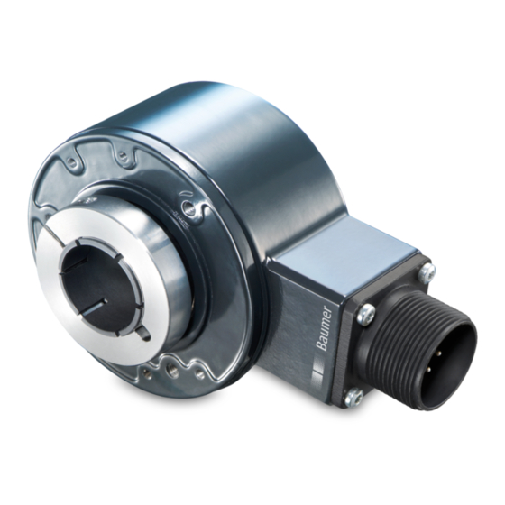
HS35
HS35 Serie
Series HS35
Merkmale
- Robustes Design bis
Schutzart IP 67
- Schockresistent bis 200 g
- Isolierhülse zum Schutz vor
Wellenströmen und Lager-
beschädigungen
- Breiter Betriebsspannungs-
bereich von 4,75...30 VDC
- Verschiedene Modelle
verfügbar
Features
- Rugged design up to IP 67
protection
- Shock resistant up to 200 g's
- Insulating sleeve to prevent
shaft currents from damaging
bearings
- Wide range supply voltage
4.75...30 VDC
- Various models available
Advertisement
Table of Contents

Related Manuals for Baumer HS35 Series


Summary of Contents for Baumer HS35 Series
- Page 1 Montage- und Betriebsanleitung Installation and operating instruction HS35 HS35 Serie Series HS35 Merkmale Features - Robustes Design bis - Rugged design up to IP 67 Schutzart IP 67 protection - Schockresistent bis 200 g - Shock resistant up to 200 g’s - Isolierhülse zum Schutz vor - Insulating sleeve to prevent Wellenströmen und Lager-...
-
Page 2: Table Of Contents
Inhaltsverzeichnis Inhaltsverzeichnis Änderungsverzeichnis ............. 4 Allgemeine Hinweise ..............6 Sicherheitshinweise ..............8 Verletzungsgefahr durch rotierende Wellen und elektrischen Strom ..8 Zerstörungsgefahr durch mechanische Überlastung........ 8 Zerstörungsgefahr durch mechanischen Schock........8 Zerstörungsgefahr durch klebende Flüssigkeiten ........8 Zerstörungsgefahr durch Verschmutzung ..........8 Zerstörungsgefahr durch elektrostatische Aufladung ...... - Page 3 Index of Contents Index of Contents Amendment History ..............5 General notes ................7 General safety instructions ............9 Risk of injury due to rotating shafts and by electric current ....9 Risk of destruction due to mechanical overload ........9 Risk of destruction due to mechanical shock ..........
-
Page 4: Änderungsverzeichnis
Änderungsverzeichnis Änderungsverzeichnis Änderung Geänderte Kapitel Beschreibung der Änderung Autor Zustand Datum Version 21.02.2012 1.00 Alle Initiale Dokumentenerstellung BTDE/rnik Erstellung 15.10.2012 2.00 Alle Komplette Überarbeitung BTDE/rnik Änderung 28.02.2013 2.01 Sicherheitshinweise Textergänzung in Kapitel 3.6 „Zerstörungs- BTDE/rnik Änderung gefahr durch elektrostatische Aufladung“ Vorbereitung / Zubehör Textänderung in Kapitel 4 &... -
Page 5: Amendment History
Amendment History Amendment History Modification Changed chapters Description of the change Author State Date Version 2012-02-21 1.00 Initial document creation BTDE/rnik Creation 2012-10-15 2.00 Complete revised version BTDE/rnik Changing 2013-02-28 2.01 General safety instructions Supplementary text in Chapter 3.6 „Risk of BTDE/rnik Changing destruction due to electrostatic charge“... -
Page 6: Allgemeine Hinweise
Details im Umgang mit Drehgebern in allen möglichen Einsatzfällen darstellen. Wir gewähren 3 Jahre Garantie im Rahmen der „Allgemeinen Verkaufs- und Lieferbedingungen“ von Baumer. Bei Rückfragen bzw. Nachlieferungen sind die auf dem Typenschild des Gerätes angegebenen Daten, insbesondere Typ und Seriennummer, unbedingt anzugeben. -
Page 7: General Notes
We offer a 3-year warranty in accordance with the „General Terms and Conditions of Sale and Delivery“ of Baumer. In the event of queries or subsequent deliveries, the data on the device type label must be quoted, especially the type designation and the serial number. -
Page 8: Sicherheitshinweise
Sicherheitshinweise Sicherheitshinweise Verletzungsgefahr durch rotierende Wellen und elektrischen Strom Haare und Kleidungsstücke können von rotierenden Wellen erfasst werden. Sor- gen Sie dafür, dass die Geräte während der Montagearbeiten nicht unkontrolliert anlaufen können. • Vor allen Arbeiten alle Betriebsspannungen ausschalten und Maschinen stillset- zen. -
Page 9: General Safety Instructions
General safety instructions General safety instructions Risk of injury due to rotating shafts and by electric current Hair and clothes may become tangled in rotating shafts. Take care that the equip- ment cannot start uncheckedly during the assembly work. • Before all work switch off all operating voltages and ensure machinery is stationa- •... -
Page 10: Zerstörungsgefahr Durch Elektrostatische Aufladung
• Die jeweiligen max. Betriebsspannungen dürfen auch kurzfristig nicht überschrit- ten werden. • Verwenden Sie nur die von Baumer empfohlenen Kabel. • Verwenden Sie für die Verbindung der Signalleitungen nur Baumer Steckverbin- der. • Steckverbinder erreichen nur mit dem zugehörigen Gegenstecker ihre angege- bene Schutzart. -
Page 11: Risk Of Destruction Due To Electrostatic Charge
• Use Baumer recommended cable only. • Use Baumer connectors to connect signal wiring only. • Stated protection can only be reached by using the appropriate connector. • When connecting the incremental encoder to the power supply, it must be obser- ved, that the supply voltage is of good quality without tension peaks. -
Page 12: Vorbereitung
Vorbereitung / Preparation Vorbereitung Preparation Lieferumfang Scope of delivery Isolierte Hohlwelle Isolated hollow shaft Klemmring Clamping ring Klemmringschraube N 8-32 UNC x Clamping ring screw N 8-32 UNC x 5/8“ 5/8“ Gehäuse Housing MIL-Stecker (7- oder 10-polig) oder MIL-connector (7- or 10-pin) or cable Kabelverschraubung gland Staubschutzdeckel (nur bei Schutz-... -
Page 13: Zur Montage Erforderlich Bzw. Empfohlen
Vorbereitung / Preparation Montage erforderlich required resp. recommen- bzw. empfohlen ded for mounting (nicht im Lieferumfang enthalten) (not included in scope of delivery) Drehmomentstütze T1: Tether arm T1: feste Länge, für Boh- fixed length, for bolt 3/8“ rung 3/8“ (9,53 mm) (9.53 mm) Kunststoffclip plastic clip... - Page 14 Vorbereitung / Preparation Reduziereinsatz: Reducer insert: für folgende Durchmes- available for the fol- ser verfügbar: 3/8“ (9,53 lowing diameters: 3/8“ mm), 1/2“ (12,7 mm), 5/8“ (9.53 mm), 1/2“ (12.7 (15,875 mm), 3/4“ (19,05 mm), 5/8“ (15.875 mm), mm), 7/8“ (22,225 mm), 3/4“...
-
Page 15: Zum Elektrischen Anschluss Erforderlich
Vorbereitung / Preparation zum elektrischen Anschluss required for electrical con- erforderlich nection (nicht im Lieferumfang enthalten) (not included in scope of delivery) CNAC 29H 10-polig Mil Spec Ge- CNAC 29H 10-pin Mil spec mating genstecker + Kabel connector + cable Anschlusskabel für HS35 mit 10-po- Connection cable for HS35 with 10- ligen MIL-Stecker. -
Page 16: Montage
Mounting Allgemeine Montagehinweise General installtation instructions • Verwenden Sie zum Befestigen • Use for fastening of the incremen- der Drehgeber nur die Baumer tal encoder only Baumer tether Drehmomentstützen. arms. • Beachten Sie alle Sicherheitshin- • Observe all safety instructions. - Page 17 Montage / Mounting Schritt 1 Step 1 • Die Aufnahmewelle sollte leicht • The receiving shaft should by light- gefettet bzw. rostschutzbehandelt ly greased or rust protected. sein. • The TIR error of the mounting shaft • Der Rundlauffehler der Welle darf should not exceed the specified value [1].
- Page 18 Montage / Mounting Schritt 3 Step 3 • Den optionalen Staubschutzdeckel • The optional dust cap fixing with mit den Befestigungsschrauben the mounting screws on the incre- an dem Drehgeber befestigen. An- mental encoder. Tightening torque zugsmoment 43-71 oz-in (0,3 - 0,5 43-71 oz-in (0.3 - 0.5 Nm).
- Page 19 Montage / Mounting Schritt 4 Step 4 • Der Drehgeber muss sich von • The incremental encoder must Hand, ohne grossen Kraftaufwand, be slide on to driveshaft by hand. auf die Motorwelle aufstecken las- Do not force! If necessary check sen.
- Page 20 Montage / Mounting Schritt 5 Step 5 • Drehgeberwelle mit Klemmring auf • Fastening the encoder shaft with der Motorwelle kraftschlüssig be- the clamp ring on the motor shaft festigen [5]. Anzugsmoment der friction-locked [5]. Tightening tor- Klemmringschraube 1,8 - 2,2 Nm. que of the clamp ring screw 1.8 - 2.2 Nm.
-
Page 21: Montage Schutzkorb (Optional Erhältlich)
Montage Schutzkorb / Mounting protective cover Montage Schutzkorb Mounting protective co- (optional erhältlich) ver (optional available) Schritt 1 Step 1 • Den Drehgeber mit Drehmoment- • Mount the encoder with tether arm stütze, wie in Grafik [6] dargestellt, as shown in graphic [6]. Tightening montieren. - Page 22 Montage Schutzkorb / Mounting protective cover Schritt 3 Step 3 • Schutzkorb mit dem gelieferten • Protective cover attach with the Zubehör (3x Zylinderschraube 3/8“ supplied accessories (3x cylin- (3/4 Inch lang) mit Unterlegschei- der screw (3/4 inch long) with flat be und Zahnscheibe) befestigen.
- Page 23 Schutzkorbs aufkleben (Grafik the opening of the protective cover [11]). (graphics [11]). [11] - Protective Cover - PN: 11080884 Baumer Ltd 122 Spring st, C-6 Southington, CT 06489 USA / Tel: 800-937-9336 Baumer Inc. 4046 Mainway Drive Burlington, Ontario, L7M4B9 Canada / Tel: 905-335-8444 www.baumer.com...
-
Page 24: Abmessungen
Masszeichnung / Dimension drawing Abmessungen Dimensions Masszeichnung Dimension drawing 3x UNC 8-32 R1.22" (R31) für Drehmomentstütze for torque support 1.75" (44.5) T1, T3 - T5 3x UNC 8-32 R1" (R25.5) ø3.15" (ø80) Isolierhülse 1.22" (31) für Staubschutzdeckel 0.79" (20) (elektrisch isoliert) for dust cap insulating sleeve (electric isolated) - Page 25 Masszeichnung / Dimension drawing Toleranzen Tolerances ø Nennmass Toleranz / ø nominal dimension tolerance Hohlwelle Drehgeber / Empfehlung Kundenwelle / hollow shaft encoder recommended customer shaft Inch/inch Metrisch/metric Inch/inch Metrisch/metric Inch/inch Metrisch/metric (in '') (in mm) (in 1/1000'') (in µm) (in 1/1000'') (in µm) 1.000''...
-
Page 26: Garantie
Garantie, Wartung / Warranty, Maintenance Garantie Warranty Die Garantie erlischt bei: Loss of warranty: • Öffnen des Drehgebers oder Be- • Unauthorized opening of incre- schädigung des QC-Siegels oder mental encoder or damaging QC- Sicherungslackes. seal or seal-mark. • Äusserlichen Beschädigungen, •... -
Page 27: Elektrischer Anschluss
Elektrischer Anschluss / Electrical Connection Elektrischer Anschluss Electrical Connection 10.1 Zerstörungsgefahr durch 10.1 Risk of destruction due to elektrostatische Aufladung electrostatic charge Siehe Punkt 3.6 in den „Sicherheits- See point 3.6 in the „General safety hinweisen“. instructions“. 10.2 Schutz vor Störeinflüssen 10.2 Interference protection •... -
Page 28: Anschlussbelegung Hs35F & Hs35P
Elektrischer Anschluss / Electrical Connection 10.3 Anschlussbelegung 10.3 Terminal assignment HS35F & HS35P HS35F & HS35P MI07: MIL-Stecker, 7-polig MI07: MIL-connector, 7-pin Stecker Belegung Connector Assignment Pin A Spur A Pin A Track A Pin B Spur B Pin B Track B Pin C Spur Z... - Page 29 Elektrischer Anschluss / Electrical Connection Kabelausgang (AWG26 Leitung) Cable gland (AWG26 wire) Aderfarben Belegung Core colour Assignment grün Spur A green Track A grau Spur B grey Track B rosa Spur Z pink Track Z violett – violet – blau blue transparent Schirm/Gehäuse...
-
Page 30: Anschlussbelegung Hs35S
Elektrischer Anschluss / Electrical Connection 10.4 Anschlussbelegung HS35S 10.4 Terminal assignment HS35S MI10: MIL-Stecker, 10-polig MI10: MIL-connector, 10-pin Stecker Belegung Connector Assignment Pin A Spur A + Pin A Track A + Pin B Spur B + Pin B Track B + Pin C Spur Z + Pin C... -
Page 31: Ausgangssignale Hs35F/P
Ausgangssignale / Output signals 10.5 Ausgangssignale HS35F/P 10.5 Output signals HS35F/P Phasenverlauf = B: Gegen den Uhrzei- Phasing = B: Counterclockwise rotation gersinn (Standard), Ansicht Klemmring- (standard) from clamping end seite Phasenverlauf = D: Im Uhrzeigersinn Phasing = D: Clockwise rotation (option) Phasenverlauf = B: Gegen den Uhrzeigersinn (Standard), Ansicht Klemmringseite. -
Page 32: Ausgangssignale Hs35S
Ausgangssignale / Output signals 10.6 Ausgangssignale HS35S 10.6 Output signals HS35S Drehrichtung im Uhrzeigersinn bei Blick Clockwise rotation when looking at the auf die Anbauseite. mounting side. 360° el. 360° el. 2.5 V A = A+ & A- 2.5 V A = A+ &... -
Page 33: Demontage
Demontage / Dismounting Demontage Dismounting 11.1 Schritt 1 (optional) 11.1 Step 1 (option) • Die Berührungsschutzfeder aus • The contact protection clip remo- der Öffnung (Stecker-/Kabelab- ve from the opening (connector/ gang) des Schutzkorbs HS35 ent- cable gland) of the protective co- fernen. - Page 34 Demontage / Dismounting 11.2 Schritt 2 11.2 Step 2 • Lösen Klemmringschraube • Loosen the clamping ring screw N 8-32 UNC x 5/8, dabei die Zylin- N 8-32 UNC x 5/8, do not unscrew derschraube nicht vollständig aus the hex socket head cap screw dem Klemmring herausdrehen! from the clamping ring! 11.3...
- Page 35 Demontage / Dismounting 11.4 Schritt 4 11.4 Step 4 • Den Drehgeber vorsichtig von der • Carefully pull down the encoder Motorwelle herunterziehen. from the motor shaft. 35 Baumer_HS35_II_DE-EN_1706.indd...
-
Page 36: Zubehör
Zubehör / Accessories Zubehör Accessories Folgendes Zubehör ist für den Dreh- following accessories geber HS35 erhältlich: available for the encoder HS35: Connectors and cables Stecker und Kabel 11128642 NAC 25E 7-pin Mil Spec 11128642 NAC 25E 7-polig Mil Mating Connector Spec Gegenstecker 11078440 CNAC 25E 7-pin Mil 11078440 CNAC 25E 7-polig Mil... - Page 37 Zubehör / Accessories 11075692 Drehmomentstütze T3, 11075692 Tether arm T3, einstellbare Länge, für adjustable length, for Bohrung 1/4“ mit bolt 1/4” with plastic clip Kunststoffclip, and screws Schrauben 11075690 Tether arm T4, 11075690 Drehmomentstütze T4, adjustable length, for einstellbare Länge, für bolt 5/16”...
-
Page 38: Technische Daten
Technische Daten Technische Daten 13.1 Mechanische Daten Baugrösse (Flansch) ø3,15" (ø80 mm) Welle ø0,375...1" (ø9,525...25,4 mm) durchgehende Hohlwelle isoliert Rundlauf der Bohrung 0.0016" (0.04 mm) Gesamtrundlauf max. Zulässiger 0,004" (0,1016 mm) radial Gesamtrundlauf (am Ausrichtungsfehler Wellenende) 0,01" (0,254 mm) axial Schutzart DIN EN 60529 IP 54, IP 65, IP 67 Betriebsdrehzahl ≤5000 U/min (siehe Temperaturdiagramm auf Seite 42) -
Page 39: Technical Data
Technical data Technical data 13.1 Mechanical data Size (flange) ø3.15" (ø80 mm) Shaft ø0.375...1" (ø9.525...25.4 mm) through hollow shaft isolated Bore runout 0.0016" (0.04 mm) TIR max. Admitted misalignment 0.004" (0.1016 mm) radial TIR (end of shaft) 0.01" (0.254 mm) axial Protection DIN EN 60529 IP 54, IP 65, IP 67 Operating speed ≤5000 rpm (see temperature diagram on page 43) -
Page 40: Elektrische Daten
Technische Daten 13.2 Elektrische Daten HS35 - allgemeine Parameter Betriebsspannung 4,75...30 VDC Verpolungsfest Abtastprinzip Optisch Störfestigkeit DIN EN 61000-6-2 Störaussendung DIN EN 61000-6-4 Zulassungen UL-Zulassung / Datei-Nr. E240061, ROHS-konform EU-Richtlinie 2011/65/EG, CE-konform HS35F Betriebsstrom ohne Last ≤40 mA (24 VDC) ≤130 mA (4,75 VDC) + Ausgangsbelastung, max. -
Page 41: Electrical Data
Technical data 13.2 Electrical data HS35 - general parameters Voltage supply 4.75...30 VDC Reverse polarity protection Yes Sensing method Optical Interference immunity DIN EN 61000-6-2 Emitted interference DIN EN 61000-6-4 Approvals UL approval / file no. E240061, ROHS compliant EU guideline 2011/65/EG, CE conform HS35F Consumption w/o load ≤40 mA (24 VDC) -
Page 42: Temperaturdiagramm
Technische Daten HS35S Betriebsstrom ohne Last ≤90 mA Sinusperioden je 1024...5000 Umdrehung Ausgabefrequenz ≤180 kHz (-3 dB) Ausgangssignale A+, A-, B+, B-, Z+, Z- Ausgangsstufen SinCos 1 Vss 13.3 Temperaturdiagramm Umgebungstemperatur + Eigenerwärmung ≤ max. Betriebstemperatur +212 °F (+100 °C) Eigenerwärmung pro 1000 U/min: IP 54: +9 °F (+5 °C) IP 65: +18 °F (+10 °C) -
Page 43: Temperature Diagram
Technical data HS35S Consumption w/o load ≤90 mA Sinewave cycles per 1024...5000 turn Output frequency ≤180 kHz (-3 dB) Output signals A+, A-, B+, B-, Z+, Z- Output stage SinCos 1 Vpp 13.3 Temperature diagram ambient temperature + self heating ≤... - Page 44 Baumer Thalheim GmbH & Co. KG Hessenring 17 DE-37269 Eschwege Phone +49 (0)5651 9239-0 Fax +49 (0)5651 9239-80 info@baumerthalheim.com www.baumer.com/motion 06/2017 · 11118411 · Version 05 · Printed in Germany Originalsprache der Anleitung ist Deutsch. Original language of this instruction is German.