
Related Manuals for Varimixer W20 F


Summary of Contents for Varimixer W20 F
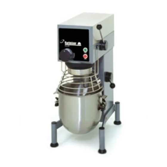
- Page 1 FOOD MIXER SPARE PART AND OPERATION MANUAL Model W20 A, J, F March 2007 1993 to Present Form 103...
- Page 2 Caution -READ BEFORE OPERATING- Varimixer recommends that mixer operators be at least 18 years of age and be thoroughly trained on the use of the mixer. Varimixer recommends that the following precautions be adopted to help make the mixer operation safer and more efficient.
-
Page 3: Limited Warranty
LIMITATIONS OF LIABILITY In the event of warranty claim or otherwise, the sole obligation of Varimixer shall be the repair and/or replacement at the option of Varimixer, of the appliance or component or part thereof Such repair or replacement shall be the expense of Varimixer except that travel over 100 miles or two hours, overtime, and holiday charges shall be,, the expense of the purchaser. -
Page 4: Table Of Contents
TABLE OF CONTENTS Installation Instructions...2 Cleaning Instructions...2 Operating Instructions...3 Specifications...4 Service Instructions...5 Main Body...11 Bowl Arms...13 Pulley System..15 Planetary Head...17 Attachment Drive...19 Front Control Panel/ Electrical Components...21 Bowl Screen...25 Tools and Bowls...27 Electrical Diagrams...29... - Page 5 DOUGH HOOK CLEANING: Special care should be given to cleaning the dough hook. The Varimixer dough hook is manufactured of stainless steel and we rec- ommend that it be cleaned and sanitized in a commercial dish machine. An alternate cleaning procedure is to vigorously scrub the dough hook with a hot water and detergent solution.
-
Page 6: Operating Instructions
Varimixer Operating Instructions W20 Place the bowl in the bowl arms. Be sure that the bowl is placed correctly and the bowl clamps are used. Set the time required by turning the timer to the right. The mixer will stop automatically when the time runs out. -
Page 7: Specifications
*On the nominal motor voltage + or – 10% tolerance is allowed. **Also available in 220/60/1 , 220/50/1 , 110/50/1. Not submitted for UL listing. ***Varimixer also features our Model W20P , specifically designed for pizza and pretzel dough. Specifications are subject to change without notice. -
Page 8: Service Instructions
SERVICE INSTRUCTIONS... -
Page 9: Service Instructions
(1) Remove the top cover of the mixer (1) and the plastic cover (43) by removing the 2 screws (3) The attachment engagement hub is taken out by removing the plastic cover (4) and the 4 bolts (5). (6) The control box is taken off by removing the 2 screws (55). (7) The special V-belt is replaced in the following way: a) Remove the top cover of the mixer (1) and the plastic cover (43). - Page 10 The planetary head is removed in the following way: a) The top cover of the mixer (1), the attachment engagement hub (3), the special V-belt (7), and the control box (6) are removed. b) The plastic ring (26) can be removed by knocking it gently on the front edge, then pressing a screwdriver between the plastic ring and the metal plate at the top of the plastic ring.
- Page 11 Mounting of the planetary head should be done in reverse order. When the lower fork (15) and the spring (34) are mounted, the speed selector lever (8) is turned counter clockwise, so that it points hori- zontally backward, at the same time as the lower fork is pressed down gently.
-
Page 12: Bowl Arms
(45) The bowl arms are to be replaced in the following way: a) Disconnect the mixer on the main switch or disconnect the connecting cable. b) Lower the bowl arms. c) Place the mixer on its back and remove the legs of the mixer (17) by removing the screws (18). d) The bottom plate (19) is removed by removing the nuts (20). - Page 14 Body...
- Page 15 Figure Number Body Description Screw Top Lid (Painted) Rear Access Plate Bushing (Lift Handle) Upper Column Plug Button Bushings Column Seal Plug Button Lower Column Bolt M8X20 Leg Left Leg Right Plug Button Rubber Foot NSF Cover Plate Suspension Hook Column Base Plate Retaining Spring f/Plate Lock Nut M6...
-
Page 16: Bowl Arms
Bowl Arms 56RN20-15 20N-65.1Z 20N-65.1M 20N-62Z... - Page 17 Figure Number Bowl Arms Description Ball (Black) Bowl Lift Lever Washer Disc Retaining Disc Crank Arm Cotter Pin Snap Ring Lift Nut Jam Nut Lift Bolt Bowl Arm Shaft Snap Ring 25U Bowl Arm Snap Ring 25U Bowl Lift Lever Assembly Lift Bolt Assembly Bowl Arm Shaft Bowl Lift Microswitch...
-
Page 18: Pulley System
Pulley System... - Page 19 Figure Number Pulley System Description Belt Grease Nipple Bolt M6x16 Motor Mount Plate Bolt 3/8-16 X 3/4 Washer Motor Pulley Pin Grease Nipple Snap Ring Set Screw ------------ Bushing Rubber Ring Spring ------------ Spring Holder ------------ Pulley Pin ------------ Bearing Fork Ring ------------ Snap Ring...
- Page 20 Pulley System Model W20P Single Speed Pizza Mixer...
- Page 21 Pulley System Model W20P Single Speed Pizza Mixer Figure Number Description Belt Motor Pulley Planetary Pulley Bolt 3/8-16X3/4 Washer Bolt M6X16 Washer Motor Part Number 20P-91 6J19 6J60 STA 5442 STA 6009 STA 5432 STA 6008 20D-85.64...
-
Page 22: Planetary Head
20N-2.1Z 20N-3 20N-2 20N-30 20-33 Planetary Head 20N-2.1Z 20-36 20N-101... - Page 23 Figure Number Planetary Head Description Snap Ring Bearing 6206 Snap Ring Bolt M6X16 Main Bearing Head Snap Ring Bearing 6206 Distance Piece Gear Wheel Rim Bolt M8X30 Main Shaft Snap Ring Eccentric Disc Bearing 6006 Snap Ring Snap Ring Seal Needle Bearing Race Groove Pin Needle Bearing set...
-
Page 24: Attachment Drive
Attachment Drive 1 1/2” 2” I.D. I.D. 20N-10.6M 20N-10.5M 20N-10.6M #17 Hub #12 Hub... - Page 25 Figure Number 10A. 11A. 15A. Attachment Drive Description Snap Ring Wormwheel Snap Ring Bearing Distance Piece Bearing Shaft F/ #17 Hub Shaft F/ #12 Hub O-ring Hub F/ #17 (2” I.D.) Hub F/ #12 (1 1/2” I.D.) Thumb Screw F/ #17 Thumb Screw F/ #12 Gasket Lock Washer...
- Page 26 Electrical Components 1993-mid 1997...
- Page 27 Electrical Components 1993-mid 1997 Figure Number * Unit must be retrofitted with new style Front panel assembly (PN 20N-650.3M No Hub)and contactor bracket (PN 20N-151.2) ** Unit must be retrofitted with new style Front panel assembly (PN 20N- 650.8M w/Hub)and contactor bracket (PN 20N-151.2) Description Front Panel No Hub Front Panel w/Hub...
- Page 28 Electrical Components 1998-Present...
- Page 29 Electrical Components 1998-Present Figure Number Front Panel Assembly No Hub Description Start Switch Assembly Stop Switch Assembly Timer Assembly 115V Timer Knob Timer Scale Front Panel Assembly Hub Front Foil w/ Hub Motor Cable Grommet Tension Relief ScScrew Screw Contactor Bracket Auxiliary Switch Contactor 110V 16 A Thermal Overload 11-16...
-
Page 30: Bowl Screen
Bowl Screen... - Page 31 Figure Number Bowl Screen Description Bowl Screen Kit Bushing Set Screw Screw Microswitch Set Screw Spacer Bolt Bushing Bracket Assembly Bolt Rear Screen Front Screen Chute Part Number 225/20N 56SN20-21.1 56SN20-21 STA 5664 STA 5251 56SN20-30 STA 5664 56SN20-22.1 56SN20-24 STA 5850 STA 5816 56SN20-21.1...
- Page 32 Tools and Attachments 1, 2 4, 5 12, 13 21, 21A 6, 7 22, 22A 23, 23A...
- Page 33 Figure Number Tools and Attachments Description S/S Bowl 20Qt S/S Bowl 12Qt. S/S Bowl 25Qt. S/S Hook 20Qt. S/S Hook 12Qt. Flat Beater 20Qt. Flat Beater 12Qt. S/S Flat Beater 20 Qt. Wire Whip 20 Qt. Wire Whip 12 Qt. S/S Wing Whip 20 Qt.
- Page 35 Timer Motor...
- Page 36 5489 Campus Drive Shreveport LA 71129 (800) 222-1138 (318) 635-3131 Fax www.varimixer.com...