
Related Manuals for Varimixer W40(A)


Summary of Contents for Varimixer W40(A)
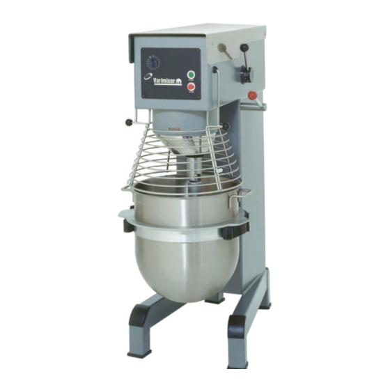
- Page 1 SPARE PART AND OPERATION MANUAL FOOD MIXER Models W30(A), W40(A), W40P, W60(A) and W60P...
- Page 2 Caution -READ BEFORE OPERATING- Varimixer recommends that mixer operators be at least 18 years of age and be thoroughly trained on the use of the mixer. Varimixer recommends that the following precautions be adopted to help make the mixer operation safer and more efficient.
-
Page 3: Limited Warranty
LIMITATIONS OF LIABILITY In the event of warranty claim or otherwise, the sole obligation of Varimixer shall be the repair and/or replacement at the option of Varimixer, of the appliance or component or part thereof Such repair or replacement shall be the expense of Varimixer except that travel over 100 miles or two hours, overtime, and holiday charges shall be,, the expense of the purchaser. -
Page 4: Table Of Contents
TABLE OF CONTENTS Installation Instructions...2 Operating Instructions...3 Cleaning-Maintenance...4 Belt Adjustments and Removal...5 Adjusting the Bowl Height...7 Machine Column...9 Bowl Arms...11 Planetary Head...13 Transmission...15 Speed Lever Assembly...17 Single Speed Transmission...19 Attachment Drive...21 Instrument Panel...23 Bowl Screen...27 Vegetable Slicer...29 Meat Mincer ...37 Bowl Scraper...43 Tools and Bowls...47 Bowl Truck...47... -
Page 5: Installation Instructions
Read this page entirely BEFORE beginning installation. VARIMIXER INSTALLATION INSTRUCTIONS The mixer must be mounted with the rubber feet, which neutralize both shaking and rusting. Spacers can be inserted under the mixer’s feet if the floor is uneven. The mixer can be bolted to the floor if desired. -
Page 6: Operating Instructions
OPERATION OF THE MIXER: Open the bowl screen and place the bowl in the bowl arms. Note: The bowl arms must be in lowest position and the bowl must be pushed all the way into the bowl arms.(Fig.3). Place the mixing tool in the bayonet shaft. The pin on the tool must be turned into the bayonet hole (fig.2). -
Page 7: Cleaning-Maintenance
Correct use of tools: Whips should never be struck against hard objects, this will decrease the life of the tool. Recommended applications for tools: Whip Beater Cream Cakes Egg Whites Waffles Mayonnaise Muffins and the like. and the like. Cleaning: The mixer should be cleaned daily or after use.The mixer should be cleaned with a soft cloth and clean water. -
Page 8: Belt Adjustments And Removal
Belt Adjustments and Removal To remove V-belts or tooth belt: 1. Remove the 4 screws (T) from the control panel. 2. Remove the front control (U) from mixer and let hang from cables. 3. Open lid. 4. Remove nut (J) and washers (H). 5. -
Page 10: Adjusting The Bowl Height
ADJUSTMENT OF BOWL HEIGHT: The distance (X) is measured from the bottom side of the bayonet hole to the surface on the bowl arms on which the bowl rests (fig.7a). The bowl arms must be lifted to normal working position. W30 = 6 3/8”... - Page 11 Bowl Lift Microswitches 1986 - Present Pre 1996 Pre 1996 1997-2001 PN 27-172 PN 27-172 PN 27-172 PN 140-173 PN 27-172 2001- Present PN 27-172 PN 81-173...
-
Page 12: Machine Column
DESCRIPTION 1. Bowl Lift Microswitch 2. Mounting Screws 3. Top Lid Threaded Bushing 4. Knee Pad 5. Intermediate Piece 6 MM 6. Indicator Arrow 8. Column 9. Lift Lever Bushings 10. Bowl Arm Shaft Bushings 12. Intermediate Piece 3 MM 13. - Page 13 1, 1A, 1B, 1C...
-
Page 14: Bowl Arms
FIG. DESCRIPTION Bowl Arm Left (Pre 1993) Bowl Arm Right (Pre 1993) Bowl Arm Left Bowl Arm Right Shock Absorber Crank Arm Bowl Arm Shaft Lifting Rod Assembly Bowl Lift Lever Extension Tube Assembly Red Ball Key B6 x 6 x 15 Washer (s) Snap Ring Lifting Nut... -
Page 16: Planetary Head
FIG. DESCRIPTION V-Belt (60 HZ) 3 per unit V-Belt (50 HZ) 3 per unit V-Belt Single Cog Belt Snap Ring Washer Planetary Pulley (60 HZ ) Planetary Pulley (50 HZ ) Pulley Single Cog Belt Bearing Snap Ring Bolt M10 x 40 MM Washer Main Bearing Distance Tube... -
Page 18: Transmission
FIG. DESCRIPTION Washer Upper Pulley for Pedestal Bearing Lower Pulley Bushing V-Belt Pulley 7A . Single Cog Belt Pulley Shaft Grease Nipple Snap Ring Bearing Snap Ring Fork Ring Distance Piece Arm for Bearing Bolt Washer Vari-Drive Belt Bearing Reducer Grease Nipple Washer Lower Motor Pully... -
Page 20: Speed Lever Assembly
FIG. DESCRIPTION Speed Lever Disc with Arrow White Clamp Black Knob Snap Ring Screw SPEED LEVER ASSEMBLY PART NUMBER per MODEL NUMBER W30 (A) W40 (A) 30N-47M 40N-47M 30N-47.10 30N-47.10 30N-47.20 30N-47.20 STA 3306 STA 3306 STA 3414 STA 3414 STA 5247 STA 5247 W40P... - Page 21 DRIVE SYSTEM FOR MODEL W40PI AND W60PI SPECIAL SINGLE SPEED TRANSMISSION...
-
Page 22: Single Speed Transmission
FIG. DESCRIPTION Motor Pulley Screw Motor Plate Belts Center Pulley Snap Ring Pedestal Shaft Pulley Snap Ring Bearing Snap Ring Washer Distance Tube Arm for Bearing Bolt SINGLE SPEED TRANSMISSION PART NUMBER W40PI W60PI 33V315 33V315 STA 5018 STA 5018 60-61 60-61 3VX400... - Page 23 IDENTIFYING A #17 HUB VERSUS A #12 HUB 2” 1.5” I.D. THIS AFFECTS ITEM NUMBERS: 7 , 7A 25, 25A 26,26A 28, 28A 34 AND 35 PLEASE DETERMINE HUB SIZE BEFORE ORDERING PARTS 20,12 11,12 13,12...
-
Page 24: Attachment Drive
FIG. DESCRIPTION Bearing Hub Wormwheel Gear Case Gear Case Cover Worm Gear Gear Shaft Attachment Drive Shaft # 17 Attachment Drive Shaft # 12 Bearing Seal Gasket Gasket Gasket Snap Ring Screw Bearing Bolt Seal Washer Washer Washer Lock Washer Rubber Ring End Cover #17 25A. -
Page 26: Instrument Panel
ELECTRICAL PANEL 1985 - JUNE 1998 FIG. DESCRIPTION Electrical Control Assembly 208-240V 3 Phase Electrical Control Assembly 230V 1 Phase Timer Assembly 208-240V Timer Assembly 480V Start Button Green Stop Button Orange Pilot Light Front Panel Timer Scale Screw Timer Knob Screw Cable Inlet Thermal Overload 3 Ph. - Page 28 ELECTRICAL PANEL JULY 1998 - PRESENT FIG. DESCRIPTION Front Panel Start Switch Assembly Stop Switch Assembly Timer Assembly 220V Timer Scale Screw Cable Inlet Cable Inlet Cover Timer Knob Grounding Clamp Screw Contactor 3 Ph. 220V 15A. Contactor 3 Ph. 480V 15B.
-
Page 30: Bowl Screen
FIG. DESCRIPTION Bowl Screen Kit Knob Lock Washer Bowl Screen Front Chute Bowl Screen Rear Set Screw Bracket Assembly Screw Microswitch Jam Nut Screw Nut for Bushing Notched Cam Body Bushing BOWL SCREEN 1993 - PRESENT PART NUMBER W30 (A) W40 (A) 225/30A 225/40A... - Page 36 VEGETABLE SLICER / CHEESE GRATER DESCRIPTION ..1. Rear Housing #17 Rear Housing #12 Bushing Snap Ring Shaft Assembly #17 Shaft Assembly #12 Shredding Disc (1/16”) Shredding Disc (1/8”) Shredding Disc (3/16”) Shredding Disc (1/4”) Grating Disc Front Door Assembly (Items # 11 thru 16) Thumb Screw Screw Fastener...
- Page 38 VEGETABLE SLICER / CHEESE GRATER ACCESSORIES DESCRIPTION Adjustable Knife Soft Vegetable Knife Screw Screw Knife Hub Knife Screw Slicing Disc (Curved) Support for Curved Knife Screw Curved Knife Screw Slicing Dics (Straight Knife) Grate ( French Fries) Grate ( Cube ) 3/8 x 3/8 Screw Tubular Front Stomper...
- Page 42 DESCRIPTION 70 MM Meat Grinder Complete #17 70 MM Meat Grinder Complete #12 Stomper Meat Tray Housing Wingnut Washer Bolt Bushing Feedscrew Knife Ring Sausage Tube 1/16” Disc 1/8” Disc 3/16” Disc 1/4” Disc 5/16” Disc 3/8” Disc 1/2” Disc Receivng Tray Adaptor #17 22A.
- Page 44 DESCRIPTION Housing #17 Housing #12 Bushing Worm with Pin #17 Worm with Pin #12 O-Ring Precutter Knife Disc 1/16” Disc 1/8” Disc 3/16” Disc 1/4” Tightening Ring Meat Tray Stomper Tray (Optional) 86 MM Meat Grinder PART NUMBER 6R001M 6R001 STA 2082 6R388 6R003M...
-
Page 46: Bowl Scraper
BOWL SCRAPER 1985-2000 (SCREW TYPE) Fig. No. Description SCRAPER HOLDER BOWL SCRAPER BOWL SCRAPER (DOWNSIZE) HOLDER WITH BLADE HOLDER WITH BLADE (DOWNSIZE) NYLON BLADE W/SCREWS NYLON BLADE W/SCREWS (DOWNSIZE) Order Number Order Number W40 / W40P 42R30-101M 42R40-101M 224/30A 224/40A 224/15 224/20B 42R30-102... - Page 48 KEYHOLE BOWL SCRAPER 2000- Fig. No. Description SCRAPER HOLDER BOWL SCRAPER BOWL SCRAPER (DOWNSIZE) HOLDER WITH BLADE HOLDER WITH BLADE (DOWNSIZE) NYLON BLADE NYLON BLADE (DOWNSIZE) Order Number Order Number W40 / W40P 42R30-101M 42R40-101M 224/30A 224/40A 224/15 224/20B 42R30-202 42R40-202 42R30A-202 42R40A-202...
- Page 49 6 , 7 3 , 4 1 , 2 9 , 10 16 , 17 12 , 13 14 , 15 18 , 19 20 , 21 27 , 28...
-
Page 50: Tools And Bowls
ATTACHMENTS AND OPTIONAL PRODUCTS FIG. DESCRIPTION Stainless Steel Bowl (Standard) Stainless Steel Bowl (Downsize) Dough Hook (Single Pin) Dough Hook (Single Pin,downsize) Tool Pin (Single) Dough Hook (Double Pin) Dough Hook (Single Pin,downsize) Tool Pin (Double) Flat Beater (Aluminum) Flat Beater (Downsize, Aluminum) Tool Pin Wire Whip Wire Whip (Downsize) - Page 51 1985 - June 1998 1 Phase...
- Page 52 1985 - June 1998 3 Phase...
-
Page 53: Electrical Diagrams
1998 - Present 1 Phase... - Page 54 1998 - Present 3 Phase...
- Page 55 5489 Campus Dr. Shreveport LA 71129 (800) 222-1138 (318) 635-3131 Fax www.varimixer.com...