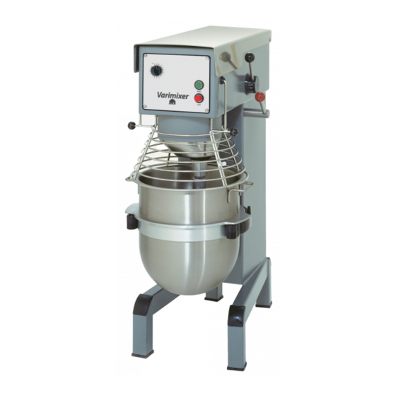
Varimixer W30 Spare Part And Operation Manual
Hide thumbs
Also See for W30:
- Motor removal instructions (3 pages) ,
- Spare part and operation manual (55 pages)

Related Manuals for Varimixer W30


Summary of Contents for Varimixer W30
- Page 1 SPARE PART AND OPERATION MANUAL FOOD MIXER Form 100 08/2010 Models W30(A), W40(A), W40P, W60(A) and W60P...
- Page 2 -READ BEFORE OPERATING- Caution Varimixer recommends that mixer operators be at least 18 years of age and be thoroughly trained on the use of the mixer. Varimixer recommends that the following precautions be adopted to help make the mixer operation safer and more efficient.
- Page 3 LIMITATIONS OF LIABILITY In the event of warranty claim or otherwise, the sole obligation of Varimixer shall be the repair and/or replacement at the option of Varimixer, of the appliance or component or part thereof Such repair or replacement shall be the expense of Varimixer except that travel over 100 miles or two hours, overtime, and holiday charges shall be,, the expense of the purchaser.
-
Page 4: Table Of Contents
TABLE OF CONTENTS Installation Instructions....................2 Operating Instructions.....................3 Cleaning-Maintenance....................4 Belt Adjustments and Removal..................5 Adjusting the Bowl Height....................7 Machine Column......................9 Bowl Arms........................11 Planetary Head......................13 Transmission.........................15 Speed Lever Assembly....................17 Single Speed Transmission..................19 Attachment Drive......................21 Instrument Panel......................23 Bowl Screen........................27 Bowl Scraper.........................29 Tools and Bowls......................33 Bowl Truck........................33 Electrical Diagrams.......................35... - Page 5 Read this page entirely BEFORE beginning installation. VARIMIXER INSTALLATION INSTRUCTIONS UNDER NO CIRCUMSTANCES ARE THE SPEED LEVER, BOWL LIFT LEVER, OR THE BOWL ARMS TO BE USED TO MOVE THE MIXER INTO PLACE. DAMAGE WILL RESULT TO THE UNIT. IT IS RECOMMENDED THAT THE TOP LID BE REMOVED BEFORE MOVING THE UNIT.
-
Page 6: Installation Instructions
OPERATION OF THE MIXER: Open the bowl screen and place the bowl in the bowl arms. Note: The bowl arms must be in lowest position and the bowl must be pushed all the way into the bowl arms. (Fig.3). Place the mixing tool in the bayonet shaft. The pin on the tool must be turned into the bayonet hole (fig.2). -
Page 7: Operating Instructions
Correct use of tools: Maintenance and Lubrication: The variable speed pulleys must be lubricated regularly, i.e. a lubrication interval of approx. 60 hours of operation. Whips should never be struck against hard objects, this will Lubrication of variable speed pulleys: decrease the life of the tool. -
Page 8: Cleaning-Maintenance
Belt Adjustments and Removal To remove V-belts or tooth belt: 1. Remove the 4 screws (T) from the control panel. 2. Remove the front control (U) from mixer and let hang from cables. 3. Open lid. 4. Remove nut (J) and washers (H). 5. - Page 10 The distance (X) is measured from the bottom side of the bayonet hole to the surface on the bowl arms on which the bowl rests (fig.7a). The bowl arms must be lifted to normal working position. W30 = 6 3/8” (X): W40 = 6 3/8” W60 = 6 15/16”...
- Page 12 81-173 27-172 140-173...
-
Page 13: Machine Column
MACHINE COLUMN DESCRIPTION PART NUMBER W30(A) W40(A) W40P W60(A) W60P 1. Bowl Lift Microswitch See Figure See Figure See Figure See Figure See Figure 2. Mounting Screws STA 5270 STA 5270 STA 5270 STA 5270 STA 5270 3. Top Lid Threaded Bushing... -
Page 15: Bowl Arms
BOWL ARMS PART NUMBER FIG. DESCRIPTION W30 (A) W40 (A) W40P W60 (A) W60P Bowl Arm Left (Pre 1993) 27-23 40-23 40-23 60-23 60-23 Bowl Arm Right (Pre 1993) 27-24 40-24 40-24 60-24 60-24 Bowl Arm Left 30N-23 40N-23 40N-23... -
Page 17: Planetary Head
PLANETARY HEAD PART NUMBER per MODEL NUMBER FIG. DESCRIPTION W40 (A) W40P W60P W30 (A) W60 (A) V-Belt (60 HZ) 3 per unit 40-90.1 (A29) 40-90.1 (A29) 40-90.1 (A29) 60-90.1 (A35) 60-90.1 (A35) V-Belt (50 HZ) 3 per unit 40-90... -
Page 19: Transmission
TRANSMISSION PART NUMBER per MODEL NUMBER FIG. DESCRIPTION W30 (A) W40 (A) W40P W60 (A) W60P Washer STA 6018 STA 6018 STA 6018 STA 6018 STA 6018 Upper Pulley for Pedestal 15-13M 15-13M 15-13M 60-13M 60-13M 30-285 30-285 30-285 60-285... -
Page 21: Speed Lever Assembly
SPEED LEVER ASSEMBLY PART NUMBER per MODEL NUMBER FIG. DESCRIPTION W30 (A) W40 (A) W40P W60 (A) W60P Speed Lever 30N-47M 40N-47M 40N-47M 60N-47M 60N-47M Disc with Arrow 30N-47.10 30N-47.10 30N-47.10 30N-47.10 30N-47.10 White Clamp 30N-47.20 30N-47.20 30N-47.20 30N-47.20 30N-47.20... - Page 22 Drive System for Model W40PI and W60PI Special Single Speed Transmission-Pizza...
-
Page 23: Single Speed Transmission
SINGLE SPEED TRANSMISSION PART NUMBER FIG. DESCRIPTION W40PI W60PI Motor Pulley 33V315 33V315 Screw STA 5018 STA 5018 Motor Plate 60-61 60-61 Belts 3VX400 3VX425 Center Pulley 33V80 33V80 Snap Ring STA 3410 STA 3410 Pedestal Shaft 15-41 60-41 STA 2022 STA 2022 Pulley 27-128... -
Page 25: Attachment Drive
ATTACHMENT DRIVE GEARBOX PART NUMBER FIG. DESCRIPTION W30 (A) W40 (A) W40P W60 (A) W60P Bearing Hub 15-5 15-5 15-5 15-5 15-5 Wormwheel 20-9 20-9 20-9 20-9 20-9 Gear Case 15-10 15-10 15-10 15-10 15-10 Gear Case Cover 15-11 15-11... -
Page 27: Instrument Panel
ELECTRICAL PANEL 1985 - JUNE 1998 PART NUMBER FIG. DESCRIPTION W30 (A) W40 (A) W40P W60 (A) W60P Electrical Control Assembly 40P-149M 40P-149M 40P-149M 40P-149M 40P-149M 208-240V 3 Phase Electrical Control Assembly 30-149M 30-149M 30-149M 30-149M 30-149M 230V 1 Phase Timer Assembly 208-240V 30-188.15M... - Page 29 ELECTRICAL PANEL JULY 1998 - PRESENT PART NUMBER FIG. DESCRIPTION W30 (A) W40 (A) W40P W60 (A) W60P Front Panel 30N-149 30N-149 30N-149 30N-149 30N-149 Start Switch Assembly 31-174.2 31-174.2 31-174.2 31-174.2 31-174.2 Stop Switch Assembly 31-174.3 31-174.3 31-174.3 31-174.3 31-174.3...
-
Page 31: Bowl Screen
BOWL SCREEN 1993 - PRESENT PART NUMBER FIG. DESCRIPTION W30 (A) W40 (A) W40P W60 (A) W60P Bowl Screen Kit 225/30A 225/40A 225/40A 225/60 225/60 STA 5810 STA 5810 STA 5810 STA 5810 STA 5810 Knob STA 3307 STA 3307... -
Page 33: Bowl Scraper
BOWL SCRAPER 1985-2000 (SCREW TYPE) Fig. No. Description Part Number W30 Part Number W40/40P Part Number W60/60P Scraper Holder 42RN30-101M 42R40-101M 42R60-101M Bowl Scraper 224/30A 224/40A 224/60 Bowl Scaper 224/15 224/20B 224/30B (downsize) Holder w/Blade 42RN30-202 42R40-202 42R60-202 Holder w/Blade... - Page 35 KEYHOLE BOWL SCRAPER 2000- Fig. No. Description Part Number W30 Part Number W40/40P Part Number W60/60P Scraper Holder 42R30-101M 42R40-101M 42R60-101M Bowl Scraper 224/30A 224/40A 224/60 Bowl Scaper 224/15 224/20B 224/30B (downsize) Holder w/Blade 42RN30-202 42R40-202 42R60-202 Holder w/Blade 42RN30A-202...
-
Page 37: Tools And Bowls
ATTACHMENTS AND OPTIONAL PRODUCTS PART NUMBER FIG. DESCRIPTION W30 (A) W40 (A) W40P W60 (A) W60P Stainless Steel Bowl (Standard) 203/30A 203/40A 203/40A 203/60 203/60 Stainless Steel Bowl (Downsize) 203/15 203/20A 203/20A 203/30B 203/30B Dough Hook (Single Pin) 213/30A 213/40A... - Page 38 1985 - June 1998 1 Phase...
-
Page 39: Electrical Diagrams
1985 - June 1998 3 Phase... - Page 40 1998 - Present 1 Phase...
- Page 41 1998 - Present 3 Phase...
- Page 42 Varimixer 14240 South Lakes Drive Charlotte, NC 28273 (800) 222-1138 www.varimixer.com...