Table of Contents
Advertisement
Quick Links
Advertisement
Table of Contents

Related Manuals for Varimixer W20D


Summary of Contents for Varimixer W20D
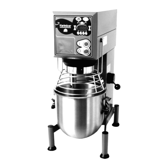
- Page 1 SPARE PART AND OPERATION MANUAL FOOD MIXER Model W20D...
- Page 2 Caution -READ BEFORE OPERATING- Varimixer recommends that mixer operators be at least 18 years of age and be thoroughly trained on the use of the mixer. Varimixer recommends that the following precautions be adopted to help make the mixer operation safer and more efficient.
-
Page 3: Limited Warranty
LIMITATIONS OF LIABILITY In the event of warranty claim or otherwise, the sole obligation of Varimixer shall be the repair and/or replacement at the option of Varimixer, of the appliance or component or part thereof Such repair or replacement shall be the expense of Varimixer except that travel over 100 miles or two hours, overtime, and holiday charges shall be,, the expense of the purchaser. -
Page 4: Table Of Contents
TABLE OF CONTENTS Installation Instructions...2 Cleaning Instructions...2 Operating Instructions...3 Front Panel Controls...4 Main Body...5 Bowl Arms...7 Pulley System...9 Planetary Head...11 Attachment Drive...13 Computer Display Panel...15 Bowl Screen...17 Tools and Bowls...19 Electrical Diagrams...21 Adjusting the Bowl Height...22 Planetary Head Removal...23... -
Page 5: Installation Instructions
Read this page entirely BEFORE beginning installation. VARIMIXER INSTALLATION INSTRUCTIONS The mixer must be mounted with the rubber feet, which neutralize both shaking and rusting. If the unit is to be installed on top of a table, the unit must be bolted down with the two bolts supplied from the shipping pallet. -
Page 6: Operating Instructions
2. Press the bar arrow between the slow and fast LEDs. 3. Press the bar arrows between the slow and fast LEDs. Note: These are the factory default times for slow and fast speed. The computer will go to factory or stored times on every power up. 1. -
Page 7: Front Panel Controls
Operation of the Mixer. Change Time in Fixed mode: 1. Press and hold the bar arrow key for 5 sec. and release. 2. The fixed time for the slow speed will appear in the display. - The LED for slow speed lights. (Left LED) 3. -
Page 8: Main Body
Body... - Page 9 Figure Number Body Description Screw Top Lid (Painted) Rear Access Plate Bushing (Lift Handle) Upper Column Plug Button Bushings Column Seal Plug Button Lower Column Bolt M8X20 Leg Left Leg Right Plug Button Rubber Foot NSF Cover Plate Suspension Hook Column Base Plate Retaining Spring f/Plate Lock Nut M6...
-
Page 10: Bowl Arms
Bowl Arms 20N-65.1Z 20N-62Z 20N-65.1M... - Page 11 Figure Number Bowl Arms Description Ball (Black) Bowl Lift Lever Washer Disc With Arrow Retaining Disc Crank Arm Cotter Pin Snap Ring Lift Nut Jam Nut Lift Bolt Bowl Arm Shaft Snap Ring 25U Bowl Arm Snap Ring 25U Bowl Lift Lever Assembly Lift Bolt Assembly Bowl Arm Shaft Assembly Part Number...
-
Page 12: Pulley System
Pulley System... - Page 13 Figure Number Pulley System Description Belt Motor Pulley Planetary Pulley Bolt 3/8-16X3/4 Washer Bolt M6X16 Washer Motor Part Number 20P-91 6J19 6J60 Local Purchase Item STA 6009 STA 5432 STA 6008 20D-85.64...
-
Page 14: Planetary Head
20N-2.1Z 20N-3 20N-2 20N-30 20-33 Planetary Head 20N-2.1Z 20-36 20N-101... - Page 15 Figure Number Planetary Head Description Snap Ring Bearing 6206 Snap Ring Bolt M6X16 Main Bearing Head Snap Ring Bearing 6206 Distance Piece Gear Wheel Rim Bolt M8X30 Main Shaft Snap Ring Eccentric Disc Bearing 6006 Snap Ring Snap Ring Seal Needle Bearing Race Groove Pin Needle Bearing set...
-
Page 16: Attachment Drive
Attachment Drive 1 1/2” 2” I.D. I.D. 20N-10.6M 20N-10.5M 20N-10.6M #17 Hub #12 Hub... - Page 17 Figure Number 10A. 11A. 15A. Attachment Drive Description Snap Ring Wormwheel Snap Ring Bearing Distance Piece Bearing Shaft F/ #17 Hub Shaft F/ #12 Hub O-ring Hub F/ #17 (2” I.D.) Hub F/ #12 (1 1/2” I.D.) Thumb Screw F/ #17 Thumb Screw F/ #12 Gasket Lock Washer...
-
Page 18: Computer Display Panel
Computer Display Control... - Page 19 Computer Display Control Figure Number Description Control Panel Assembly with start/stop buttons and computer display. Start Button Assembly Stop Button Assembly Screw Interface Board Assembly Front Plate Casting Ribbon Cable Cube Relay Part Number 20E-605M 31-174.2 31-174.3 STA 5230 20E-606 20N-650.5 8073882 8070834...
-
Page 20: Bowl Screen
Bowl Screen... - Page 21 Figure Number Bowl Screen Description Bowl Screen Kit Bushing Set Screw Screw Microswitch Set Screw Spacer Bolt Bushing Bracket Assembly Bolt Rear Screen Front Screen Chute Part Number 225/20N 56SN20-21.1 56SN20-23 STA 5664 STA 5251 56SN20-30 STA 5664 56SN20-22.1 56SN20-24 STA 5850 STA 5816 56SN20-21.1...
-
Page 22: Tools And Bowls
Tools and Attachments 1, 2 4, 5 12, 13 21, 21A 6, 7 22, 22A 23, 23A... - Page 23 Figure Number Tools and Attachments Description S/S Bowl 20Qt S/S Bowl 12Qt. S/S Bowl 25Qt. S/S Hook 20Qt. S/S Hook 12Qt. Flat Beater 20Qt. Flat Beater 12Qt. S/S Flat Beater 20 Qt. Wire Whip 20 Qt. Wire Whip 12 Qt. S/S Wing Whip 20 Qt.
-
Page 24: Electrical Diagrams
Start N.O. Stop N.C. Bowl Screen Microswitch Wiring Diagram Blue White Green Black Orange Motor Plug 115V Black Green White... -
Page 25: Adjusting The Bowl Height
Bowl Height Adjustment A) Lower the bowl arms. B) Loosen the counter nut (2) and remove the cotter pin. (1) C) Remove the lifting bolt (6) and the lifting nut. (8) D) Adjust the bowl height by turning the lifting nut (8) either in or out, on the lifting bolt. -
Page 26: Planetary Head Removal
...-On repair of the planetary head: Grease the toothed wheel and the toothed rim with Nye Gel .868VH, (PN WHITE GREASE), the needle bearings in the planetary head must not be ...lubricated with this type of grease, they should be lubricated with Lubriplate #1200-2..Do not use any other type of grease than the ones stated here. -
Page 27: Planetary Head Removal
Planetary Head Removal 1. Remove the top lid (1), attachment hub (7), the drive belt (2) and the front ...control panel (4). 2. The plastic ring (13) can be removed with a screwdriver by pressing it ...between the plastic ring and the frame, and then prying it down. 3. - Page 28 5489 Campus Drive Shreveport LA 71129 (800) 222-1138 (318) 635-3131 Fax...