Table of Contents
Advertisement
Quick Links
Advertisement
Table of Contents

Related Manuals for Varimixer V20


Summary of Contents for Varimixer V20
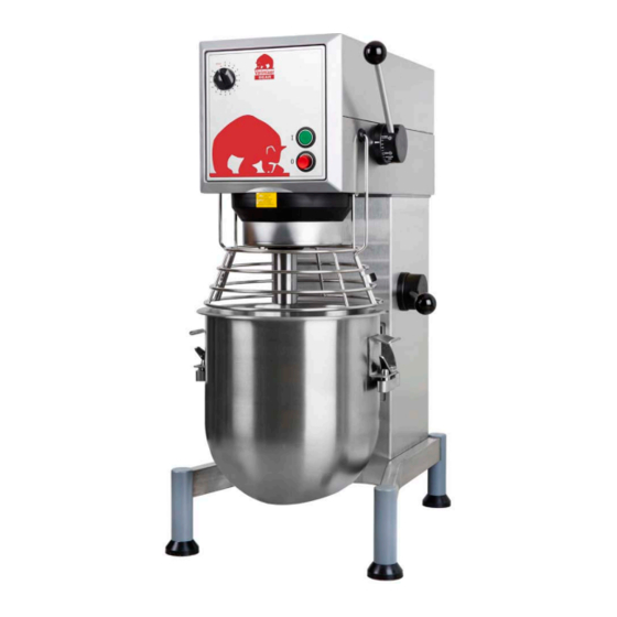
- Page 1 SPARE PART AND OPERATION MANUAL FOOD MIXER Model V20 012016...
-
Page 2: U Npacking
-READ BEFORE OPERATING- Caution Varimixer recommends that mixer operators be at least 18 years of age and be thoroughly trained on the use, cleaning and lubrication of the mixer. This manual should be seen as an integral part of the mixer and should be kept by the machine throughout its working life. -
Page 3: Limited Warranty
LIMITATIONS OF LIABILITY In the event of warranty claim or otherwise, the sole obligation of Varimixer shall be the repair and/or replacement at the option of Varimixer, of the appliance or component or part thereof Such repair or replacement shall be the expense of Varimixer except that travel over 100 miles or two hours, overtime, and holiday charges shall be,, the expense of the purchaser. -
Page 4: Table Of Contents
The machine may only be used as specified in this manual. Unless the change is recommended by the manufacturer, modifying the machine is prohibited. If the machine is fitted with an attachment drive, only accessories produced or recommended by Varimixer should be attached. -
Page 5: T Echnical Data
onsTrUcTion of The mixer Attachment Hub Machine Label Arrow indicating the rotation direction of the planetary head Toothed Belt Planetary Head Motor Bayonet Socket Bowl Lift Bottom Plate Bowl Lift Arms Screws for fixing on table Nut retaining the bottom plate imension skeTch echnical daTa Gross weight ........233 Lbs. -
Page 6: S Afety
afeTy The machine is designed for the manufacture of products that do not trigger any reactions or release substances that may be harmful to the user when in use. User safety is assured as follows: • Tools can only rotate when the bowl screen is closed and the bowl is lifted. •... -
Page 7: Perating Nstructions
Varimixer BEAR Place the mixing tool in the bayonet Place the tool in the bowl. Raise the bowl to working position by shaft. The pin of the tool must be Place the bowl in the bowl arms. pulling the handle forward. Ensure that turned into the bayonet hole. -
Page 8: Verloading
Dough Hook Cleaning: Special care should be given to cleaning the dough hook. The Varimixer dough hook is manufactured of stainless steel and we recommend that it be cleaned and sanitized in a commercial dish machine. An alternate cleaning procedure is to vigorously scrub the dough hook with a hot water and detergent solution. -
Page 9: Ervice Nstructions
ervice nsTrUcTions... - Page 10 ervice nsTrUcTions (1) Remove the top cover of the mixer (1) and the plastic cover (43) by removing the 2 screws (3) The attachment engagement hub is taken out by removing the plastic cover (4) and the 4 bolts (5). (6) The control box is taken off by removing the 2 screws (55).
- Page 11 The planetary head is removed in the following way: a) The top cover of the mixer (1), the attachment engagement hub (3), the special V-belt (7), and the control box (6) are removed. b) The plastic ring (26) can be removed by knocking it gently on the front edge, then pressing a screwdriver between the plastic ring and the metal plate at the top of the plastic ring.
- Page 12 See Drawing Mounting of the planetary head should be done in reverse order. When the lower fork (15) and the spring (34) are mounted, the speed selector lever (8) is turned counter clockwise, so that it points hori- zontally backward, at the same time as the lower fork is pressed down gently.
- Page 13 (45) The bowl arms are to be replaced in the following way: a) Disconnect the mixer on the main switch or disconnect the connecting cable. b) Lower the bowl arms. c) Place the mixer on its back and remove the legs of the mixer (17) by removing the screws (18). d) The bottom plate (19) is removed by removing the nuts (20).
-
Page 14: Achine Olumn
achine olUmn 06020-0407... - Page 15 achine olUmn Fig. No. Description Part Number Top Lid ......................20D-21 Screw.......................STA5090 Upper Column ..................RN20N-22.13RS Bushing (Lift Handle) ..................STA 2515 Lower Column .....................CR20-22.30R Column Base Plate ..................20N-22.35 Rear Plate....................CR20-22.17R1 Plug Button ..................... STA 6535 NSF Cover Plate................... RN20-304.1 Leg Left, sold as ...................
-
Page 16: Ifting Ystem
ifTing ysTem 21, 21A 56RN20-15 20N-62Z 20N-65.1M 20N-68.5M... - Page 17 ifTing ysTem Fig. No. Description Part Number Key ........................STA 2019 Snap Ring ......................STA 3407 Snap Ring 25U ....................STA 3410 Jam Nut .......................STA 5825 Washer ........................STA 6066 Cotter Pin......................STA 6204 Rivet ........................STA 6488 Bowl Lift Lever ......................20N-62Z Ball (Black) ......................STA 3306 Crank Arm......................RN20-63ME Screw........................STA 5251 Bowl Lift Microswitch ..................56SN20-30...
-
Page 18: Ulley Ystem
Ulley ysTem... -
Page 19: P Ulley Ystem
Ulley ysTem Fig. No. Description Part Number Belt ......................... 20-91 Grease Nipple......................STA 3220 Bolt M6x16......................STA 5432 Motor Mount Plate ....................RN20-61.1 Bolt 3/8-16 X 3/4 ....................STA 5442 Washer ........................STA 6018 Motor Pulley Pin ....................60-285 Grease Nipple......................STA 3220 Snap Ring ......................STA 3410 Set Screw ......................STA 5601 Bushing........................STA 2505 Rubber Ring ......................20N-228... -
Page 20: P Lanetary H Ead
laneTary 20N-2.1Z 20N-3 20N-2 20N-2.1M 20-36 20N-30 20-33 20N-101... - Page 21 laneTary Fig. No. Description Part Number Snap Ring ......................STA 3414 Bearing 6206 ......................20-99 Snap Ring ......................STA 3518 Bolt M6X16 ......................STA 5432 Main Bearing Head ....................20N-3 Snap Ring ......................STA 3518 Bearing 6206 ......................20-98 Distance Piece......................20-37 Gear Wheel Rim .....................20N-1 Bolt M8X30 ......................STA 5626 Main Shaft ......................20N-30 Snap Ring ......................STA 3470...
-
Page 22: Ttachment H Ub
TTachmenT 2î I.D. 1 ½” I.D. RN20-10.6M9 #12 Hub... - Page 23 TTachmenT Fig. No. Description Part Number Snap Ring ......................STA 3410 Wormwheel ......................20N-9 Snap Ring ......................STA 3512 Bearing ......................... 15-105 Distance Piece.......................20N-37 Bearing ........................15-105 Key ........................STA 2031 Shaft F/ #12 Hub ....................RN20-50.6 O-ring........................STA 3127 Hub F/ #12 (1 1/2” I.D.)..................RN20-8.6M9 Thumb Screw F/ #12 M8 x 1.5 ................4R-125 Hub Ring.......................20N-211 Lock Washer ......................STA 6038...
-
Page 24: Lectrical Omponents
lecTrical omponenTs... - Page 25 lecTrical omponenTs Fig. No. Description Part Number Start Switch Assembly ..................AR31-174.2 Stop Switch Assembly ..................31-174.3 Timer Assembly ....................W30-188.1Z Timer ........................ W30-188.1 Timer Knob ......................30-189 Front Panel ....................RN20-650.30M9 Front Foil ......................RN20-149.53 Motor Cable Grommet ..................STA 3078 Cable inlet......................STA 3014 Nut ........................
-
Page 26: Owl Creen
creen 56SN20-15... - Page 27 creen Fig. No. Description Part Number Bowl Screen Kit ....................14020-0001 Bushing......................56SN20-21.1 Cam ........................56SN20-23 Set Screw ......................STA 5501 Screw........................STA 5251 Microswitch ......................56SN20-30 Set Screw ......................STA 5664 Cam ........................56SN20-22.1 Spacer ........................56SN20-24 Bolt ........................STA 5270 Nut ........................STA 5816 Bushing......................56SN20-21.1 Bracket Assembly ....................56SN30-13 Nut ........................STA 5850 Bolt ........................STA 5360...
-
Page 28: Ttachments
ools and TTachmenTs 1, 2 3, 4 7, 8 14, 15 12, 13 16, 17... - Page 29 ools and TTachmenTs Fig. No. Description Part Number S/S Bowl 20Qt ......................203/20N S/S Bowl 12Qt......................203/12N S/S Hook 20Qt...................... 213/20A S/S Hook 12Qt......................213/12N S/S Flat Beater 20Qt................... 205/20A Alu. Flat Beater 12Qt ....................205/12N Heavy Wire Whip 20 Qt..................221/20A Wire Whip 12 Qt.
-
Page 30: E Lectrical D Iagram
lecTrical iagram... - Page 32 14240 South Lakes Drive Charlotte, NC 28273 (800) 222-1138 www.varimixer.com...