Table of Contents
Advertisement
Operator's Manual
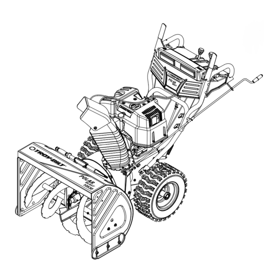
SNOW THROWER
Model 10530
Polar Blast
IMPORTANT: READ SAFETY RULES AND INSTRUCTIONS CAREFULLY
WARNING:
This unit is equipped with an internal combustion engine and should not be used on or near any unimproved forest-
covered, brush-covered or grass-covered land unless the engine's exhaust system is equipped with a spark arrester meeting applicable local
or state laws (if any). If a spark arrester is used, it should be maintained in effective working order by the operator. In the State of California the
above is required by law (Section 4442 of the California Public Resources Code). Other states may have similar laws. Federal laws apply on
federal lands. A spark arrester for the muffler is available through your nearest engine authorized service dealer or contact the service
department, P.O. Box 361131 Cleveland, Ohio 44136-0019.
TROY-BILT LLC, P.O. BOX 361131 CLEVELAND, OHIO 44136-0019
. 769-00293B.fm
FORM NO
PRINTED IN U.S.A.
(6/2004)
Advertisement
Table of Contents

Related Manuals for Troy-Bilt Polar Blast 10530


Summary of Contents for Troy-Bilt Polar Blast 10530
-
Page 1: Snow Thrower
A spark arrester for the muffler is available through your nearest engine authorized service dealer or contact the service department, P.O. Box 361131 Cleveland, Ohio 44136-0019. TROY-BILT LLC, P.O. BOX 361131 CLEVELAND, OHIO 44136-0019 . 769-00293B.fm FORM NO PRINTED IN U.S.A. - Page 2 This information will be necessary to use the manufacturer’s web site and/or help from the Customer Support Department or an authorized service dealer. TROY-BILT LLC P. O. BOX 3 6 1 1 3 1 www.troybilt.com...
- Page 3 SECTION 1: IMPORTANT SAFE OPERATION PRACTICES This symbol points out important safety instructions, which if not followed, could endanger the personal safety and/or property of yourself and others. Read and follow all instructions in this manual before attempting to operate this machine. Failure to comply with these instructions may result in personal injury.
-
Page 4: Maintenance And Storage
Never operate with a missing or damaged chute assembly. Keep all safety devices in place and working. Never run an engine indoors or in a poorly ventilated area. Engine exhaust contains carbon monoxide, an odorless and deadly gas. Do not operate machine while under the influence of alcohol or drugs. -
Page 5: Hardware Pack
SECTION 2: ASSEMBLING YOUR SNOW THROWER NOTE: All references to right or left side of the snow thrower are determined from behind the unit in the operating position. The “operator’s position” is defined as standing directly behind the snow thrower, facing the handle panel. - Page 6 Actuator Brackets and Springs Figure 3 Attaching Chute Assembly • Place chute assembly over chute opening, with the opening in the chute assembly facing the front of the unit. • Place chute flange keepers beneath lip of chute assembly, with the flat side of chute flange keeper facing downward.
- Page 7 Routing Chute Tilt Cables • If not already routed, slip the cables that run from beneath the handle panel to the chute assembly through the cable guide located on top of the engine housing. See Figure 6. Cable Guide Discharge Chute Figure 6 SECTION 3: KNOW YOUR SNOW THROWER WARNING:...
- Page 8 Drive Control / Auger Control Lock Headlights Fuel Tank Discharge Chute Chute Clean-out Tool Auger Auger Control The auger control is located on the left handle. Squeeze the auger control to engage the augers. Release to stop the snow throwing action. The drive control must also be released in order to stop the auger.
-
Page 9: Before Starting
SECTION 4: OPERATING YOUR SNOW THROWER Before Starting WARNING: Read, understand, and follow all instructions and warnings on the machine and in this manual before operating. Gas And Oil Fill-up Service the engine with gasoline and oil as instructed in the separate engine manual packed with your snow thrower. -
Page 10: To Stop Engine
• As engine warms up, rotate choke knob slowly to OFF position. If engine falters, return to FULL choke, then slowly move to OFF position. To Stop Engine • Run engine for a few minutes before stopping to help dry off any moisture on the engine. •... -
Page 11: Operating Tips
• Repeat Auger Control Test to verify proper adjustment has been achieved. Repeat the previous steps to provide more slack in the cable, if necessary. To Engage Wheel Drive • With the engine running near top speed, move the shift lever into one of the six FORWARD positions or two REVERSE positions. - Page 12 cable) from the drive actuator bracket. See Figure • Push the cable coupler through the end of the spring to expose the lock nut. See Figure 10. • Thread the lock nut outward (down the coupler) three full turns to provide more slack in the cable and reattach the spring to the bracket.
- Page 13 NOTE: If the tire pressure is not equal on both sides, the unit may pull to one side or the other. WARNING: Under any circumstance do not exceed manufacturer’s recommended psi. Equal tire pressure should be maintained at all times. Excessive pressure when seating beads may cause tire/rim assembly to burst with force sufficient to cause serious injury.
-
Page 14: General Recommendations
SECTION 6: MAINTAINING YOUR SNOW THROWER WARNING: Before lubricating, repairing, or inspecting, disengage all controls and stop engine. Wait until all moving parts have come to a complete stop. Disconnect the spark plug wire and ground it against the engine to prevent unintended starting. - Page 15 Lube Cams Here Control Rods Figure 16 Be careful not to allow grease to get on the IMPORTANT: drive plate or friction wheel. Drive Control / Auger Control Lock The cams on the ends of the control rods which interlock the drive and auger controls must be lubricated at least once a season or every 25 hours of operation using a multi-purpose automotive grease.
- Page 16 Shear Bolts Flange Lock Nut Carriage Bolt Figure 17 • Reassemble the new shave plate, making sure heads of carriage bolts are to the inside of the housing. Tighten securely. Replacing Belts To remove and replace either the auger belt or the drive belt, follow the steps below and then proceed to the specific steps listed under respective sub-headings.
- Page 17 Brake Bracket Assembly Belt Keepers Figure 21 • Remove and replace auger belt inside belt keepers. • Reassemble pulley to auger housing with hex bolt and bell washer (cupped side toward the pulley). Make sure key is in place on shaft and brake puck is seated in the pulley groove.
- Page 18 Shift Arm Assembly Shift Arm Sprocket Assembly Sprocket Hex Shaft Friction Wheel Friction Wheel Screws Bonded Friction Wheel Figure 23 Shift Arm Sprocket Sprocket Assembly Hex Shaft Hex Hub Of Sprocket Friction Wheel Figure 24 NOTE: If the sprocket fell from the snow thrower while removing the hex shaft, place the sprocket on the hex shaft.
- Page 19 Auger control cable in need of adjustment. Auger belt loose or damaged. Shear bolt(s) sheared. NOTE: For repairs beyond the minor adjustments listed above, contact an authorized Troy-Bilt service dealer. Cause Fill tank with fresh gasoline. Clean the fuel line.
- Page 20 SECTION 9: PARTS LIST FOR MODEL 10530 REAR VIEW...
- Page 21 Model 10530 Ref. Part No. Part Description 05244A Bearing Housing 618-0281A Auger Brake Bracket Assembly 684-0090A 16” Impeller Assembly 710-0371 Hex Lock Bolt 5/16-18 x.875” 710-0451 Carriage Bolt 5/16-18 x .750” 710-0459A Hex Screw, Special 3/8-24 x 1.5” 710-0528 Hex Screw 5/16-18 x 1.25” 710-0726 Self-Tapp.
- Page 22 Model 10530 14 51 52 37 27 75...
- Page 23 Model 10530 Ref. Part No. Part Description 741-0225 Hex Flange Bearing 750-1302A Spacer,.6725 x 1.125 x 2.485 618-0279 Dogg Assembly LH 618-0280 Dogg Assembly RH 618-0282D Drive Shaft Assembly 618-04178 Friction Wheel Assembly 684-0162 Support Bracket Assembly 684-0161 Shift Arm Assembly 684-04103 Shift Rod Assembly 684-0118...
- Page 24 Model 10530...
- Page 25 Model 10530 Ref. Part No. Part Description 646-0012 Auger/Drive Cable Assembly 684-0053B Lower Chute Directional Control 705-5266 Split Chute Directional Control Brkt. 710-1879 Hex Screw, 3/8-16 x.88” 710-1878 Hex Screw, 3/8-16 x 1.75” 710-0458 Carriage Bolt 5/16-18 x 1.75” 710-0572 Carriage Bolt 5/16-18 x 2.5”...
- Page 26 Model 10530 Ref. Part No. Description 07386 Washer 684-0123A Belt Cover Bracket Assembly 710-0191 Hex Screw 3/8-24 x 1.25” 710-0237 Hex Screw 5/16-24 x .625” 710-1008 Self-tapping Sems Screw 710-0607 TT Screw 5/16-18 x 0.5” 710-0672 Hex Lock Screw 5/16-24 x 1.25” 712-0116 Jam Nut 714-0118...
- Page 27 Model 10530 Ref. NOTE: When rebuilding a gearbox assembly, include 3 oz. of Shell Alvania EP Lead-Free Grease (Part No. 737-0168). Part No. Description 618-0246 Housing Assembly, RH 618-0435 Housing Assembly, LH 710-1260A Screw, 5/16-18 x 0.75 738-0492 Spiral Axle 711-1133 Auger Drive Shaft 714-0126...
- Page 28 Model 10530 Ref. Part No. Description 710-0276 Carriage Screw 710-0458 Carriage Bolt 5/16-18 x 1.75” 710-0805 Hex Bolt 5/16-18 x 1.5” 710-0895 Hex Screw 1/4-15 x.750” 710-0597 Hex Screw 1/4-20 x 1.00” 712-04063 Flange Lock Nut, 5/16-18 712-04064 Flange Lock Nut, 1/4-20 731-0846C Upper Chute 731-0851A...
- Page 29 NOTES...
- Page 30 NOTES...
- Page 31 MANUFACTURER’S LIMITED COMMERCIAL WARRANTY The limited warranty set forth below is given by Troy-Bilt LLC with respect to new merchandise used for commercial purposes and purchased and used in the United States and/ or its territories and possessions, and by MTD Products...
- Page 32 MANUFACTURER’S LIMITED WARRANTY FOR: The limited warranty set forth below is given by Troy-Bilt LLC with respect to new merchandise purchased and used in the United States and/or its territories and possessions, and by MTD Products Limited with respect to new merchandise purchased and used in Canada and/or its territories and possessions (either entity respectively, “Troy-Bilt”).