Table of Contents
Advertisement
Safety • Set-Up • Operation • Adjustments • Maintenance • Troubleshooting • Parts Lists • Warranty
OPERATOR'S MANUAL
www.troybilt.ca
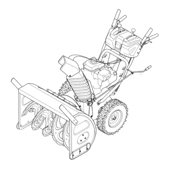
Two-Stage Snow Thrower
IMPORTANT:
READ SAFETY RULES AND
INSTRUCTIONS CAREFULLY
BEFORE OPERATING EQUIPMENT.
769-04094
P. O. Box 1386, KITCHENER, ONTARIO N2G 4J1
PRINTED IN U.S.A.
06/10/08
Advertisement
Table of Contents

Related Manuals for Troy-Bilt Troy-Bilt


Summary of Contents for Troy-Bilt Troy-Bilt
- Page 1 Safety • Set-Up • Operation • Adjustments • Maintenance • Troubleshooting • Parts Lists • Warranty OPERATOR’S MANUAL www.troybilt.ca Two-Stage Snow Thrower IMPORTANT: READ SAFETY RULES AND INSTRUCTIONS CAREFULLY BEFORE OPERATING EQUIPMENT. 769-04094 P. O. Box 1386, KITCHENER, ONTARIO N2G 4J1 PRINTED IN U.S.A.
-
Page 2: Table Of Contents
This Operator’s Manual is an important part of your new snow thrower. It will help you assemble, prepare and maintain the unit for best performance. Please read and understand what it says. Safety Symbols... 3 Safe Operation Practices ... 4 Setting Up Your Snow Thrower ... -
Page 3: Safety Symbols
This page depicts and describes safety symbols that may appear on this product. Read, understand, and follow all instructions on the machine before attempting to assemble and operate. Symbol READ THE OPERATOR’S MANUAL(S) Read, understand, and follow all instructions in the manual(s) before attempting to assemble and operate. -
Page 4: Safe Operation Practices
DANGER: This machine was built to be operated according to the safe operation practices in this manual. As with any type of power equipment, carelessness or error on the part of the operator can Safe result in serious injury. This machine is capable of amputating hands and feet and throwing objects. Failure to observe the following safety instructions could result in serious injury or death. - Page 5 Operation 1. Do not put hands or feet near rotating parts, in the auger/ impeller housing or chute assembly. Contact with the rotating parts can amputate hands and feet. 2. The auger/impeller control lever is a safety device. Never bypass its operation. Doing so makes the machine unsafe and may cause personal injury.
-
Page 6: Setting Up Your Snow Thrower
Setting Up Your Snow Thrower NOTE: This Operator’s Manual covers several models. Snowthrower featrues vary by model. Not all features refer- enced in this manual are applicable to all snowthrower models. NOTE: References to right or left side of the snow thrower are deter- mined from behind the unit in the operating... - Page 7 Figure 3-4 • Slide chute assembly over chute opening, making sure the flange keepers are beneath lip of chute adapter. The notches should engage with the spiral end of the chute crank. See Figure 3-5. • Secure flange keeper, locknuts and screws previously removed.
-
Page 8: Final Adjustments
Setting Up Your Snow Thrower WARNING Never use your hands to clean snow and ice from the chute assembly or auger housing. IMPORTANT Under any circum- stance do not exceed manufacturer’s recom- mended psi. Equal tire pressure should be maintained at all times. Excessive pressure when seating beads may cause tire/rim... - Page 9 If you experienced resistance rolling the unit, either when repositioning the shift lever from 6 to R2 or when attempting to move the machine with the drive control released, adjust the drive control immediately. To adjust, proceed as follows: • Loosen the nylock nut on the drive control cable and unthread the cable one full turn.
-
Page 10: Operating Your Snow Thrower
Operating Your Snow Thrower WARNING Read, understand, and follow all instruc- tions and warnings on the machine and in this manual before operating. Now that you have set up your snow thrower for opera- tion, get acquainted with its controls and features. These Use extreme care are described below and illustrated on this page. - Page 11 Auger Control The auger control is located on the left handle. Squeeze the auger control to engage the augers. Release to stop the snow throwing action. The drive control must also be released in order to stop auger. Drive Control / Auger Control Lock The drive control is located on the right handle.
-
Page 12: Starting The Engine
Service the engine with gasoline and oil as instructed in the separate engine manual packed with your unit. Read instructions carefully. Starting The Engine Operating 1. Make certain both the auger control and drive control are in the disengaged (released) position. Your Snow 2. -
Page 13: Operating Tips
Operating Tips NOTE: Allow the engine to warm up for a few minutes. The engine will not develop full power until it reaches operating temperature. WARNING: The temperature of the muffler and the surrounding areas may exceed 150° F (65° C). Avoid these areas. -
Page 14: Makingadjustments
Making Adjustments WARNING Shift Rod If the full range of speeds (forward and reverse) cannot be achieved, refer to Figure 5-1 and adjust the shift rod as follows: Read, understand, 1. Looking underneath the handle panel, note which and follow all instruc- of the three holes in the shift lever the ferrule is tions and warnings inserted into. -
Page 15: Skid Shoes
Skid Shoes The space between the shave plate and the ground can be adjusted by raising or lowering the skid shoes. For close snow removal, as when using on a smooth concrete or asphalt driveway, place the skid shoes in the low position. -
Page 16: Maintaining Your Snow Thrower
Friction Wheel Maintaining Your Snow Thrower Drive Plate WARNING Shear Pin Before lubricating, repairing or inspecting, disengage all controls and stop engine. Wait until all moving parts have come to a complete stop. Remove the safety key to prevent unintended firing of the engine. - Page 17 2. Remove the plastic belt cover, located near the engine, by removing the three self-tapping screws that secure it. See Figure 6-4. 3. a. Loosen the bolt shown in Figure 6-5 securing the belt keeper bracket and remove the other bolt. b.
-
Page 18: Drive Belt
8. Place a block of wood underneath the auger housing as shown in Figure 6-9 and separate auger housing from the frame by tilting the housing forward and pulling up the handles. 9. Block the impeller with a piece of wood to prevent if from spinning and use a 1/2”... - Page 19 4. Install the new belt on the pulleys in the reverse order and re-tension with the idler pulley. 5. Reassemble your unit by performing the previous steps in the opposite order. Changing Friction Wheel Rubber WARNING: Run the engine completely dry of gasoline before tipping snowthrower.
-
Page 20: Off-Season Storage
If unit is to be stored over 30 days, prepare for storage as instructed in the separate engine manual packed with your snow thrower. • Clean snow thrower thoroughly. • Lubricate as instructed in the Maintenance section of this manual. Off-Season •... -
Page 21: Trouble Shooting
Problem 1. Choke not in ON position. Engine fails to start 2. Spark plug wire disconnected. 3. Fuel tank empty or stale fuel. 4. Engine not primed. 5. Faulty spark plug. 6. Blocked fuel line. 7. Safety key not in ignition on engine. 8. -
Page 22: Warranty
How to Obtain Service: Warranty service is available, with proof of purchase, through your local MTD Authorized Service Dealer. If you do not know the dealer in your area, please write to the Service Department of MTD PRODUCTS LIMITED, P.O. BOX 1386, KITCHENER, ONTARIO N2G 4J1. - Page 23 NOTES: For parts and/or accessories refer to customer support on page 2. Adressez-vous au «Service après-vente» à la page 2 pour ce qui concerne les pièces et/ou accessoires.
- Page 24 Styles K, L & Q Style Q 34 36 Styles K & L...
-
Page 25: Parts List
PART N° DE N° DE RÉF PIÈCE DE SCRIP TION 631-04180 Han dle Panel Ass’y - Yel low 631-04183 Han dle Panel Ass’y-Black w/Chute Con trol 631-04133A LH Clutch Lock Han dle Ass’y 631-04134B RH Clutch Lock Han dle Ass’y 684-04105B En gage ment Han dle As sem bly LH 684-04106B... - Page 26 B&S 305-342 cc Torque to 21 ft./lbs. maximum, washer should be flat./ Serrez à un couple de 21 pi-lb maximum. La rondelle doit être plate. When rebuilding gear box fill one housing half completely with grease 838-0168./Pour remonter la boîte d'engrenages, remplissez complètement une moitié...
- Page 27 PART N° DE N° DE RÉF PIÈCE DE SCRIP TION 736-0159 Flat Washer .349 ID x .879 OD x .063 714-0104 Int. Cot ter Pin 754-0222A V-Belt 1/2 x 44" Lg. 754-04131 V-Belt 1/2 x 42" Lg. 736-0505 Flat Washer .34 x 1.5 x .150 720-0284 Han dle Knob As sem bly 710-1245B...
- Page 28 PART N° DE N° DE RÉF PIÈCE Au ger Shaft 738-04155 Shear Pin 5/16-18 x 1.75 618-0246 Gear Hous ing Half - RH 741-0192 Flange Bear ing 714-0126 #9 HI-Pro Key 3/16 x 3/4 Dia HT 711-04714 Au ger Drive Shaft 716-0111 Snap Ring for .875 dia.
- Page 29 NOTES: For parts and/or accessories refer to customer support on page 2. Adressez-vous au «Service après-vente» à la page 2 pour ce qui concerne les pièces et/ou accessoires.
- Page 30 Torque to 325-550 in./lbs Serrez à un couple de 325-550 po-lb. B&S B&S Torque to 325-450 in./lbs Serrez à un couple de 325-450 po-lb. Tec.
- Page 31 PART N° DE N° DE RÉF PIÈCE DE SCRIP TION 05244B Bear ing Hous ing 618-0279 LH Dog As sem bly 618-0280 RH Dog As sem bly 618-0282E Steer ing Shaft As sem bly 618-04178 Wheel Ass’y Bear ing 6.0" OD 718-04034 Fric tion Wheel Bonded 710-0896...
- Page 32 N° DE RÉF Parts List Pièces détachées For parts and/or accessories refer to customer support on page 2. Adressez-vous au «Service après-vente» à la page 2 pour ce qui concerne les pièces et/ou accessoires. Wheel As sem bly En sem ble de roue 634-0225 (LH) 634-0226 (RH) 634-04179A (LH)
- Page 33 NOTES: For parts and/or accessories refer to customer support on page 2. Adressez-vous au «Service après-vente» à la page 2 pour ce qui concerne les pièces et/ou accessoires.
- Page 34 accessoires. et/ou pièces concerne pour page à après-vente» «Service Adressez-vous page support customer refer accessories and/or parts NOTES:...
- Page 35 12.08.06 responsable n’est LIMITED PRODUCTS obligations exprimée. limitée garantie garanties compris tacites, préalable écrite autorisation d’une complète machine 4J1. après-vente, service adressez-vous con- vous d’achat. preuve d’une agréé concessionnaire-réparateur d’achat. date compter dans manière même garanties COMMERCIALES. CONSIDÉRÉES PERSON- L’UTILISATION COMMERCIALES.
- Page 36 cisaillement. tarière. bâton. l’outil Dégagez l’intérieur Nettoyez d’entraînement. technique. d’aération. chapeau. bougie. machine vibrations tous Serrez après-vente. service technique. adressez-vous technique. détails, plus Pour mineurs. d’entretien réservoir problèmes d’essence concerne chapitre REMARQUE: plein remplacez Dépannage propre départ”. goupille Remplacez d’entretien. Régime Voir commande...
- Page 37 silicone. légère d’huile couche roulements ressorts, chaînes, machine Enduisez rouille. contre bien aéré, métallique abri à machine remiser avant endroit dans souffleuse page à lubrification renseignements souffle- l’extérieur débris moteur. d’utilisation notice accompagne moteur d’utilisation fournies instructions selon façon jours, plus pendant entreposé...
- Page 38 souffleuse avec châssis. serrez gauche fendillements. apercevez vous d’usure signes l’apparition dès frottement roue caoutchouc bague Remplacez périodiquement. vérifiée être devrait s’user à tendance frottement roue caoutchouc bague AVERTISSEMENT hexagonal Entretien l’arbre Glissez frottement normale. fonctionnement position dans Reposez auto-taraudeuses. place châssis couvercle...
- Page 39 poulie d’entraînement courroie bas. d’entraînement poulie d’entraînement courroie doucement. tension poulie Relâchez 6-11. Voir tension. poulie courroie tension. relâcher pour d’entraînement courroie l’arrière tension poulie précédemment. fournies instructions courroie démontez fait, été encore d’entraînement: 6-11 Figure 6-10 Figure poulie Fente l’adaptateur Taquet Figure...
- Page 40 exact. modèle votre représenter peuvent seulement indicatif titre à fournies sont photos obligation. préavis sans modifiées être peuvent techniques caractéristiques usée. paraît courroie toute Remplacez souffleuse. d’utilisation heures toutes d’entraînement courroie tarières courroie l’état Vérifiez souffleuse. votre garantie couverts seront résultant composants d’autres...
- Page 41 fond. à Serrez l’intérieur trouve ordinaires boulons assurant vous neuve plate lame l’habitacle maintiennent contre-écrous ordinaires boulons plate: lame 6-3. Figure Voir niveau. être pour patins Assurez-vous précédemment. boulonnerie avec patins nouveaux souffleuse. maintiennent embase à contre-écrous échéant) plate rondelle ordinaires boulons patins:...
- Page 42 plate. lame entre maximal ment dégage- assurer pour haute plus position à patins réglez gravier, recouverte surface souffleuse utiliser devez vous quelconque, raison pour matériels. dégats corporelles blessures causer peut tarière, projeté s’il qui, gravier recouverte surface souffleuse d’utiliser déconseillé IMPORTANT: Réglages support...
- Page 43 couvre-châssis. obtenu. voulu l’ajustement câble maintenir pour contre-écrou Resserrez besoin. selon câble dévissez vissez l’entraînement câble contre-écrou Desserrez suivant l’ajustement faites Sinon, 5-3. Figure d’entraînement. plaque touche frottement vérifiez l’entraînement, commande 5-3. Figure Voir vitesses. levier toutes à d’entraînement, plaque roue entre d’espace...
- Page 44 système. frottement roue prématuré l’usage causera Ceci roues. l’entraînement l’embrayage lâché d’abord avoir sans vitesses levier JAMAIS déplacez IMPORTANT souffleuse. mieux connaissiez vous jusqu’à lentes plus vitesses vous Servez- REMARQUE: boulonnerie souffleuse. ajustements notice entretenir toucher. bénéficier Évitez (65°C). d’une 150°F dépasser peut...
- Page 45 normale. fonctionnement température lorsqu’il puissance toute développe quelques pendant tourner moteur Laissez VOLET. SANS position à lentement PLEIN, VOLET position à départ volet nouveau à tournez hésite, moteur SANS position vers départ volet bouton lente- tournez chauffe, moteur mesure retenant. tout lentement s’enrouler...
- Page 46 souffleuse. moteur mouvement pièces toutes ajustés vêtements cheveux pieds, mains, toujours Éloignez mortel. inodore carbone, monoxyde contiennent moteur d’échappement ventilé. clos local dans l’intérieur à moteur tourner jamais faites utilisation. pendant démarrage lors souffleuse proximité à tient personne Assurez-vous espaces souffleuse.
- Page 47 moteur. marche pour » « position doit moteur arrêter bascule à Interrupteur l’équipement. autorisée utilisation éviter pour sécurité clé Enlevez démarre. pour enfoncée bien être doit sécurité sécurité remplissage. goulot moteur à d’huile niveau vérifier d’huile froid. temps moteur démarrer à...
- Page 48 selon réduisez recommandée avant l’expédition. irrégulière. sera raclage pneuma- plaque l’usure l’autre plus chapitre côté d’un tirer risque machine pneus, abaissez- tous dans égale n’est pression IMPORTANT main. à goulotte dans tarière près glace neige jamais dégagez AVERTISSEMENT plastique. montage Instructions besoin.
- Page 49 «Réglages». dans roues» l’entraînement section consultez détails, plus Pour satisfaisant. quand câble contre-écrou l’ajustement. 3-12. Figure Voir complet. tour dévissez l’entraînement commande câble trouve contre-écrou suit l’entraînement commande ajustez débrayée, l’entraînement commande alors machine déplacer essayez vous position à position déplacé...
- Page 50 correctement. risque sans fonctionne souffleuse votre vérifier pour ajustements tous effectuez instructions soigneusement suivez Lisez page à tarière» «Commande à vous référez- souffleuse, votre d’utiliser Avant AVERTISSEMENT montage Instructions Figure conducteur jusqu’à Figure dents partie manivelle souffleuse. orientant Figure 3-7. Voir d’essence.
- Page 51 collets. guides autres deux contre-écrous n’enlevez mais Voir goulotte. collets guides maintiennent contre-écrous goulotte «Réglage». dans goulotte» support «Réglage Référez-vous est. besoin ajusté, être peut support tôt. plus retiré goupille-épingle rondelle avec place maintenez-la support dans manivelle l’extrémité goulotte. manivelle goupille-épingle plate rondelle...
- Page 52 machine. notice cette dans figurent instructions ments avertisse- respecter comprendre lire, peuvent personnes utilisée être doit machine Cette 06.09.08 responsabilité Votre SYMBOLE! recomman- sont ACCOMPAGNE dispositifs L’AVERTISSEMENT sta- machine RESPECTEZ fonctionnement. utile corporelles. américaine blessures entraîner “U.S. peut instructions Com- non-respect machine.
- Page 53 état. sont qu’ils assurez-vous place sécurité dispositifs tous Laissez elle d’éjection goulotte sans jamais relâchées. sont lorsqu’elles débrayage automatiquement revenir directions deux dans fonctionner doivent commande manettes corporelles. blessures machine l’emploi dangereux rendrait jamais contournez sécurité. dispositif tarière l’ensemble commande pieds.
- Page 54 machine. notice cette dans figurent instructions ments avertisse- respecter comprendre lire, peuvent personnes utilisée être doit machine Cette responsabilité Votre SYMBOLE! ACCOMPAGNE L’AVERTISSEMENT RESPECTEZ corporelles. blessures entraîner peut instructions carbone, non-respect bâtiment machine. cette servir vous d’essayer avant d’utilisation notice cette dans figurant...
- Page 55 votre poursuivre pouvoir déterminer pour précédent veuillez sujet, à renseignements indiquée, puissance performances, 1-800-668-1238. ci-dessous: options l’une Choisissez commandes, concernant après-vente. vendue, l’a vous modèle notice cette anglaise page (voir saison attentivement lire donc renseignements fournit vous avant série numéro d’enregistrer chapitre lire...
- Page 56 06/10/08 769-04094 phases www.troybilt.ca D’UTILISATION Entretien ONTARIO KITCHENER, MACHINE. AVANT INSTRUCTIONS RÈGLES deux neige Garantie détachées pièces Réglages Fonctionnement 1386, ÉTATS-UNIS MARCHE ATTENTIVEMENT IMPORTANT: à Souffleuse NOTICE Listes Dépannage Montage Sécurité IMPRIMÉ METTRE SÉCURITÉ LISEZ...