Table of Contents
Advertisement
615TCF/615TCS
USER'S MANUAL
M/B For Socket 370 Pentium
III Processor
NO. G03-615CFR3A
Release date: May 2002
Trademark:
* Specifications and Information contained in this documentation are furnished for information use only, and are
subject to change at any time without notice, and should not be construed as a commitment by manufacturer.
Advertisement
Table of Contents

Related Manuals for JETWAY 615TCFR3A


Summary of Contents for JETWAY 615TCFR3A
- Page 1 615TCF/615TCS USER'S MANUAL M/B For Socket 370 Pentium III Processor NO. G03-615CFR3A Release date: May 2002 Trademark: * Specifications and Information contained in this documentation are furnished for information use only, and are subject to change at any time without notice, and should not be construed as a commitment by manufacturer.
-
Page 2: Table Of Contents
TABLE OF CONTENT USER’S NOTICE ................ii MANUAL REVISION INFORMATION ..........1 THERMAL SOLUTIONS..............1 CHAPTER 1 INTRODUCTION OF MOTHERBOARD 1-1 FEATURE OF MOTHERBOARD............... 2 1-2 SPECIFICATION ..................3 1-3 PERFORMANCE LIST ................4 1-3-1 615TCF/615TCS .................... 1-4 LAYOUT DIAGRAM & JUMPER SETTING ........... 5 CHAPTER 2 HARDWARE INSTALLATION 2-1 HARDWARE INSTALLATION STEPS ............. -
Page 3: User's Notice
3-9 PNP/PCI CONFIGURATION SETUP............39 3-10 PC HEALTH STATUS................. 40 3-11 MISCELLANEOUS CONTROL ..............41 3-12 LOAD STANDARD/OPTIMIZED DEFAULTS ........42 3-13 SET SUPERVISOR/USER PASSWORD ........... 42 CHAPTER 4 DRIVER & FREE PROGRAM INSTALLATION MAGIC INSTALL SUPPORTS WINDOWS 95/98/98SE/NT4.0/2000 ..... 43 4-1 INF ....... -
Page 4: Manual Revision Information
Manual Revision Information Reversion Revision History Date Third Edition May 2002 Item Checklist Motherboard Cable for IDE/Floppy CD for motherboard utilities ¡ ¼ Cable for USB Port 3/4 (Option) User’s Manual Intel Processor Family Thermal Solutions As processor technology pushes to faster speeds and higher performance, thermal management becomes increasingly crucial when building computer systems. -
Page 5: Feature Of Motherboard
Introduction of 615TCF/615TCS Motherboard 1-1 Feature of motherboard The 615TCF/615TCS motherboard is design for use Intel’s new generation Pentium processors, which utilize the Socket 370 design and the memory size expandable to 512MB. This motherboard uses the newest Intel 815E B-Step/815EP B-Step chipset, supports Tualatin, Coppermine, Celeron processors whose 133MHz front side bus &... -
Page 6: Performance List
∗ Micro ATX form factor 4 layers PCB size: 24.5x19cm Design ∗ Intel 815E B-Step Chipset for 615TCF Chipset ∗ Intel 815EP B-Step chipset for 615TCS ∗ ICS 950502 Clock Generator Clock Generator ∗ Support 66/100/133MHz system Bus Clock (CPU Bus Clock) ∗... -
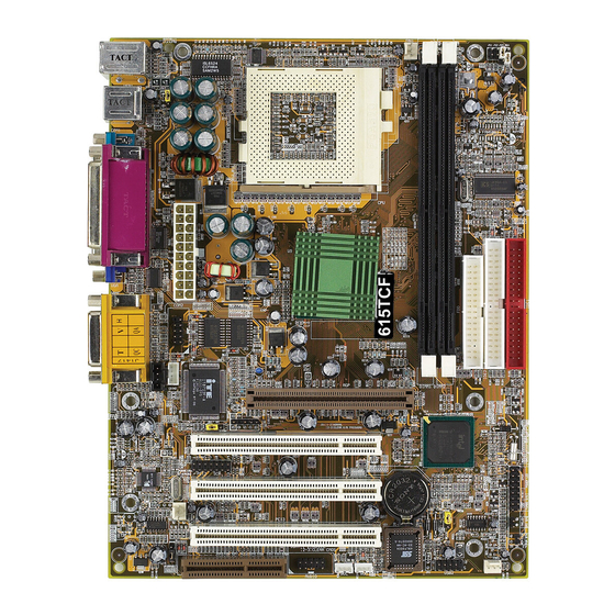
Page 7: Layout Diagram & Jumper Setting
The following performance data list is the testing result of some popular benchmark testing programs. These data are just referred by users, and there is no responsibility for different testing data values gotten by users (the different Hardware & Software configuration will result in different benchmark testing results.) ... - Page 8 PRINT GAME/MIDI PORT PS/2 MOUSE PS/2 Keyboard USB1 COM1 LINE-IN for 615TCF only LINE-OUT FAN1 CPU F.S.B. Clock Select Jumper K/B Power ON Jumper 370 CPU Socket ATX Power Connector DIMM Socket X2 PC99 Back Panel Intel 815E/EP Chip Floppy Connector ATA 100 IDE Connector COM2 Connector...
-
Page 9: Chapter 2 Hardware Installation
JS3, JS4 2-pin Block Keyboard Power ON Function Setting 3-pin Block JBAT CMOS RAM Clear 3-pin Block Connectors Connector Name Description Page ATX-PWR ATX Power Connector 20-pin Block p.17 PS2 KB/MOUSE PS/2 Mouse & PS/2 Keyboard 6-pin Female p.17 Connector USB1 USB Port Connector 4-pin Connector... -
Page 10: Hardware Installation Steps
2-1 Hardware installation Steps Before using your computer, you had better complete the following steps: 1. Check motherboard setting 2. Install CPU 3. Install Memory 4. Install Expansion cards 5. Connect Ribbon cables, Panel wires, and power supply 6. Setup BIOS 7. -
Page 11: Glossary
your computer, this feature requires an ATX power supply that can supply at least 300mA on the +5VSB lead. The default is set on disable. 1-2 closed : Disabled (default) 2-3 closed : Enabled Keyboard Power On Function 3. CMOS RAM Clear (3-pin) : JBAT A battery must be used to retain the motherboard configuration in CMOS RAM short 1-2 pins of JBAT to store the CMOS data. - Page 12 Chipset (core logic) - two or more integrated circuits which control the interfaces between the system processor, RAM, I/O devises, and adapter cards. Processor socket - the socket used to mount the system processor on the motherboard. Slot (AGP, PCI, ISA, RAM) - the slots used to mount adapter cards and system RAM. AGP - Accelerated Graphics Port - a high speed interface for video cards;...
-
Page 13: Setting Cpu Bus Clock & Memory Clock Jumper
RB : FC–PGA packing : P2–133MHz front side bus frequency PY–100MHz front side bus frequency 866 : CPU internal frequency, where here is 866MHz 256 : the size of L2 cache, where here is 256K Celeron FC–PGA On the surface of the CPU as shown on the right picture, under the word of “Celeron” the code is: 566/128/66/1.5V 566 : CPU internal frequency, where here is 566MHz... -
Page 14: Install Cpu
CPU/SDRAM (MHz) AUTO 66/100 (default) 100/100 133/100 133/133 Example: Using a Pentium III 866 CPU with front side bus frequency of 133MHz and PC-133 SDRAM module, the setting of JS3 will be 1-2 and JS4 will be 2-3. This sets both CPU BUS CLOCK and SDRAM CLOCK to be 133MHz. -
Page 15: Overclock Running
WARNING! Be sure that there is sufficient air circulation across the processor’s heatsink and CPU cooling FAN is working correctly, otherwise it may cause the processor and motherboard overheat and damage, you may install an auxiliary cooling FAN, if necessary. To install a CPU, first turn off your system and remove its cover. -
Page 16: Install Memory
133/133 CMOS Setup Utility – Copyright(C) 1984-2000 Award Software Miscellaneous Control CyrixIII Clock Ratio Default Item Help Auto Detect DIMM/PCI Clk Enabled Spread Spectrum Disabled ** Current Host Clock is 66Mhz ** Menu Level > CPU Host/SDRAM/PCI Clock 66/100/33Mhz CPU Clock Ratio CyrixIII CPU Ratio Adjust Move Enter:Select Item +/-/PU/PD:Value F10:Save ESC:Exit... -
Page 17: Expansion Cards
According the specification when SDRAM clock is 133MHz only can support 2 pcs Double Sided DIMMs DS : Double Sided DIMM SS : Single Sided DIMM NOTE! Make sure the total installed memory does not exceeds 512MB, otherwise the system may hang during startup. Generally, installing SDRAM modules to your motherboard is very easy, you can refer to figure 2-4 to see what a 168-Pin PC100 &... -
Page 18: Procedure For Expansion Card Installation
2-5-1 Procedure For Expansion Card Installation 1. Read the documentation for your expansion card and make any necessary hardware or software setting for your expansion card such as jumpers. 2. Remove your computer’s cover and the bracket plate on the slot you intend to use. 3. -
Page 19: Aimm/Agp Slot
Onboard VGA √ Onboard USB 0 √ Onboard USB 1 √ AC97/MC97 IMPORTANT! If using PCI cards on shared slots, make sure that the drivers support “Shared IRQ” or that the cards don’t need IRQ assignments. Conflicts will arise between the two PCI groups that will make the system unstable or cards inoperable. - Page 20 ATX power supply turned on, the full power will not come into the system board until the front panel switch is momentarily pressed. Press this switch again will turn off the power to the system board. ROW2 ROW1 3.3V 3.3V -12V 3.3V Soft Power On...
- Page 21 PS/2 MOUSE PRINT GAME/MIDI PORT LINE-IN PS/2 Keyboard USB1 COM1 for 615TCF only LINE-OUT Floppy drive Connector (34-pin block): FLOPPY This connector supports the provided floppy drive ribbon cable. After connecting the single plug end to motherboard, connect the two plugs at other end to the floppy drives.
-
Page 22: Headers
Pin 1 Pin 1 Secondary IDE Connector Primary IDE Connector • Two hard disks can be connected to each connector. The first HDD is referred to as the “Master” and the second HDD is referred to as the “Slave”. • For performance issues, we strongly suggest you don’t install a CD-ROM or DVD-ROM drive on the same IDE channel as a hard disk. - Page 23 IDE Activity LED: IDELED This connector connects to the hard disk activity indicator light on the case. Turbo LED switch: TBLED Since the motherboard’s turbo function is always on. The turbo LED will remain constantly on while the system power is on. You may wish to connect the Power LED from the system case to this lead.
- Page 24 NOTE: This feature requires that BIOS Wake-Up by PCI Card is enabled. Wake-On-LAN Headers (11) FAN Speed Headers (3-pin) : FAN1, FAN2, FAN3 These connectors support cooling fans of 350mA (4.2 Watts) or less, depending on the fan manufacturer, the wire and plug may be different. The red wire should be positive, while the black should be ground.
- Page 25 (13) Audio Front Panel Header (9-pin): AUDIO This header connect to Front Panel Line-In, Line-out, MIC connector with cable. AUDIO Pin 1 Audio Front Panel Headers (14) CD Audio-In Headers (4-pin) : CDIN2 CDIN2 is the connector for CD-Audio Input signal. Please connect it to CD- ROM CD-Audio output connector.
-
Page 26: Starting Up Your Computer
2-7 Starting Up Your Computer 1. After all connections are made, close your computer case cover. 2. Be sure all the switch are off, and check that the power supply input voltage is set to proper position, usually in-put voltage is 220V∼240V or 110V∼120V depending on your country’s voltage used. -
Page 27: Chapter 3 Introducing Bios
Chapter 3 Introducing BIOS The BIOS is a program located on a Flash Memory on the motherboard. This program is a bridge between motherboard and operating system. When you start the computer, the BIOS program gain control. The BIOS first operates an auto-diagnostic test called POST (power on self test) for all the necessary hardware, it detects the entire hardware device and configures the parameters of the hardware synchronization. -
Page 28: Getting Help
3-2 Getting Help Main Menu The on-line description of the highlighted setup function is displayed at the bottom of the screen. Status Page Setup Menu/Option Page Setup Menu Press F1 to pop up a small help window that describes the appropriate keys to use and the possible selections for the highlighted item. - Page 29 Integrated Peripherals Use this menu to specify your settings for integrated peripherals. Power Management Setup Use this menu to specify your settings for power management. PnP/PCI configurations This entry appears if your system supports PnP/PCI. PC Health Status This entry shows your PC health status. Miscellaneous Control Use this menu to specify your settings for Miscellaneous Control.
-
Page 30: Standard Cmos Features
3-4 Standard CMOS Features The items in Standard CMOS Setup Menu are divided into several categories. Each category includes no, one or more than one setup items. Use the arrow keys to highlight the item and then use the <PgUp> or <PgDn> keys to select the value you want in each item. CMOS Setup Utility –... -
Page 31: Advanced Bios Features
If the controller of HDD interface is CD-ROM, the selection shall be “None” Access Mode The settings are Auto Normal, Large, and LBA. Cylinder number of cylinders number of heads Head Precomp write precomp Landing Zone landing zone number of sectors Sector 3-5 Advanced BIOS Features CMOS Setup Utility –... - Page 32 Enabled Activates automatically when the system boots up causing a warning message to appear when anything attempts to access the boot sector of hard disk partition table. CPU L1 Cache The default value is Enabled. Enabled (default) Enable cache Disable cache Disabled Note: The L1 cache is built in the processor.
-
Page 33: Advanced Chipset Features
On (default) Keypad is numeric keys. Keypad is arrow keys. Gate A20 Option The A20 signal is controlled by keyboard controller or chipset hardware. Normal Fast (default) The A20 signal is controlled by port 92 or chipset specific method. Typematic Rate Setting Keystrokes repeat at a rate determined by the keyboard controller. -
Page 34: Advanced Chipset Features
The Advanced Chipset Features Setup option is used to change the values of the chipset registers. These registers control most of the system options in the computer. CMOS Setup Utility – Copyright(C) 1984-2000 Award Software Advanced Chipset Features On-Chip VGA Setting Press Enter Item Help SDRAM Timing Setting... -
Page 35: Sdram Timing Setting
During Enabled, A deferrable CPU cycle will only be Deferred after it has been in a Snoop Stall for 31 clocks and another ADS# has arrived. During Disabled, A deferrable CPU cycle will be Deferred immediately after the GMCH receives another ADS#. Delayed Transaction The chipset has an embedded 32-bit posted write buffer to support delay transactions cycles. -
Page 36: Integrated Peripherals
When synchronous DRAM is installed, the number of clock cycles of CAS latency depends on the DRAM timing. The settings are: 2 and 3. SDRAM Cycle Time Tras/Trc Select the number of SCLKs for an access cycle. The settings are: 5/7 and 6/8. SDRAM RAS-to-CAS Delay This field let’s you insert a timing delay between the CAS and RAS strobe signals, used when DRAM is written to, read from, or refreshed. -
Page 37: On-Chip Ide Function
Please refer to section 3-7-3 Init Display First This item allows you to decide to activate whether PCI Slot or on-chip VGA first. The settings are: PCI Slot, AGP Slot, On-Chip VGA. Power On Function This function allows you to select the item to power on the system. The settings are: Button Only, Mouse Left, Mouse Right, Password, Hotkey, and keyboard 98. -
Page 38: On-Chip Sio Function
Ultra DMA/33 implementation is possible only if your IDE hard drive supports it and the operating environment includes a DMA driver (Windows 95 OSR2 or a third-party IDE bus master driver). If your hard drive and your system software both support Ultra DMA/33 and Ultra DMA/66, select Auto to enable BIOS support. -
Page 39: On-Chip Device Function
: Standard Parallel Port : Enhanced Parallel Port : Extended Capability Port SPP/EPP/ECP/ECP+EPP To operate the onboard parallel port as Standard Parallel Port only, choose “SPP.” To operate the onboard parallel port in the EPP modes simultaneously, choose “EPP.” By choosing “ECP”, the onboard parallel port will operate in ECP mode only. -
Page 40: Power Management Setup
This item allows you to decide to enable/disable the 815 chipset family to support AC97 Modem. The settings are: Enabled, Disabled. Game Port Address/Midi Port Address This will determine which Address the Game Port/Midi Port will use. 3-8 Power Management Setup The Power Management Setup allows you to configure your system to most effectively save energy saving while operating in a manner consistent with your own style of computer use. - Page 41 User Define(default) Allows you to set each mode individually. When not disabled, each of the ranges is from 1 min. to 1hr. except for HDD Power Down that ranges from 1 min. to 15 min. and disable. Video Off Method This determines the manner in which the monitor is blanked.
-
Page 42: Pnp/Pci Configuration Setup
Date(of month) Alarm You can choose which month the system will boot up. Set to 0, to boot every day. Time(hh:mm:ss) Alarm You can choose what hour, minute and second the system will boot up. Note: If you have change the setting, you must let the system boot up until it goes to the operating system, before this function will work. -
Page 43: Pc Health Status
reconfiguration has caused such a serious conflict that the operating system can not boot. The settings are: Enabled and Disabled. Resource Controlled By The Award Plug and Play BIOS has the capacity to automatically configure all of the boot and Plug and Play compatible devices. -
Page 44: Miscellaneous Control
Vcore/VTT/3.3V/+5V/+12V/-12V/ -5V/VBAT(V)/5VSB(V) This will show the CPU/FAN/System voltage chart and FAN Speed. Shutdown Temperature This option is for setting the Shutdown temperature level for the processor. When the processor reaches the temperature you set, this will shutdown the system. 3-11 Miscellaneous Control This section is for setting CPU Miscellaneous Control. -
Page 45: Set Supervisor/User Password
Load Standard Defaults (Y/N)? N Pressing <Y> loads the BIOS default values for the most stable, minimal-performance system operations. Load Optimized Defaults When you press <Enter> on this item, you get a confirmation dialog box with a message similar to: Load Optimized Defaults (Y/N)? N Pressing <Y>... -
Page 46: Magic Install Supports Windows 95/98/98Se/Nt4.0/2000
DRIVERS you need and some free application programs and utility programs. In addition, this CD also include an auto detect software which can tell you which hardware is installed, and which DRIVERS needed so that your system can function properly. We call this auto detect software MAGIC INSTALL. -
Page 47: Ide Install Intel Ultra Ata Storage Driver
shown below: 1. Click INF in the MAGIC INSTALL MENU 2. Click NEXT when Chipset Software Install Utility appears 3. This chart shows motherboards supported 4. Select if you want computer re-started by the driver click NEXT click Finish NOTE: MAGIC INSTALL will auto detect file path X:\INTEL815\INF\INFINST.EXE This driver supports WINDOWS 95/98/98SE/ME/2000 (NT4.0 do not require) 4-2 IDE... -
Page 48: Vga Install On-Board Vga Driver
1. Click IDE when MAGIC INSTALL MENU 2. Click NEXT when INTEL Ultra ATA Storage appears Wizard appears 3. This is to announce the Copy Right click 4. Click NEXT or BROWSE to change the path NEXT you want the driver stored 5. -
Page 49: Ac97 Sound Driver And The Program Install For Editing/Playback
A. For WINDOWS 95/98/98SE/ME/NT4.0/2000 1. Click VGA when MAGIC INSTALL MENU Click NEXT when INTEL 81X Family appears Chipset Graphics Driver Software appears 3. Click NEXT, this is to announce Copy Right 4. Select if you want to re-start computer and click Finish NOTE: The path of the file... -
Page 50: Pc-Health Installs Smart Guardian Software For Hardware Monitoring Device
3. When ask Remove old device driver, Click OK 4. Click Finish and Restart Windows NOTE: MAGIC INSTALL will auto detect file path: X:\CODEC\ALC201\SETUP.EXE (for WINDOWS 95/98/98SE/ME/NT4.0/2000) 4-5 PC-HEALTH installs SMART GUARDIAN software for hardware monitoring device 1. Click PC-HEALTH when MAGIC INSTALL 2. - Page 51 3. This to assign the path of the file, click OK 4. Click OK after the software is installed NOTE: MAGIC INSTALL will auto detect file path X:\INTEL815\HEALTH\SETUP.EXE This driver supports WINDOWS 95/98/98SE/NT4.0/2000 4-6 PC-CILLIN Install PC-CILLIN 2000 Anti-virus program 1.
- Page 52 5. Click OK and If You Have Proxy Server, 6. Click NEXT when Start Copy Files, Start to Enter Your Setting. install the software. 7. If you want to make a rescue disc, insert a 8. Setup Complete and click Finish 1.44 MB disc 9.
-
Page 53: Magic Bios Install Bios Live Update Utility
4-7 MAGIC BIOS Install BIOS Live Update Utility Click Magic BIOS when Magic Install Click Next to install the Magic BIOS in MENU appears Destination Folder After finish Setup you will have a Magic Double click the Magic BIOS icon you will BIOS icon in your screen have this picture, choose from internet you can upgrade BIOS On-line... -
Page 54: Microsoft Directx 8.0 Driver
Click Yes if you want to update the BIOS When System programming BIOS don’t turn otherwise choose No to exit off power, after finish update BIOS, the system will clear CMOS and automatically Restart When choose From Local Driver to update 10. -
Page 55: How To Utilize Pc-Health
1. Click START/PROGRAMS/AVANCE 2. This utility it can play from CD the effect just SOUND MANAGER/AVRACK. Then like HI-FI stereo system, also it can play ALSRACK appears *.WAV, *.MID, *.MP3, *.MPG format file 3. This is a sound environment simulator offering massive simulation including environment of opera pub stadium KARAOK playing having high low KEY tuning. -
Page 56: How To Disable On-Board Sound
You may re-set temperature and voltage by click OPTION 4-11 HOW TO DISABLE ON-BOARD SOUND Enter BIOS SETUP choose INTEGRATE PERIPHERALS choose ON-CHIP DEVICE FUNCTION choose AC97 AUDIO Disable on-board sound function by press PAGE DOWN KEY to Disable 4-12 HOW TO UPDATE BIOS STEP 1.