Table of Contents
Advertisement
For Pentium
The author assumes no responsibility for any errors or omissions which
may appear in this document nor does it make a commitment to update the information
contained herein.
Trademark:
*
Pentium is registered trademark and MMX is a trademark of Intel corporation,
the other names and brands are the property of their respective owners.
*
Specifications and Information contained in this documentation are furnished for information use only, and are subject to
change at any time without notice, and should not be construed as a commitment by manufacturer.
Chapter 1
9BXAS/9BXAS-A
9BXAN/9BXAN-A
USER'S MANUAL
PCI/ AGP Mainboard
II/ III or Socket 370
NO. G03-9BXASR7A
Release date: NOV 2000
** Year 2000 compliant **
TABLE OF CONTENT
Advertisement
Table of Contents

Related Manuals for JETWAY J9BXAS-7A


Summary of Contents for JETWAY J9BXAS-7A
- Page 1 9BXAS/9BXAS-A 9BXAN/9BXAN-A USER'S MANUAL PCI/ AGP Mainboard For Pentium II/ III or Socket 370 The author assumes no responsibility for any errors or omissions which may appear in this document nor does it make a commitment to update the information contained herein.
-
Page 2: Table Of Contents
....................1 1-1 Preface ................1 1-2 Feature of Motherboard ..................1 1-2-1 Overview .................. 2 1-2-2 Key Feature Chapter 2 Hardware Installation .................. 3 ....................3 2-1 Unpacking ..............4 2-2 The Diagram of Motherboard ....5 2-3 Quick Reference for Jumpers, Connectors & Expansion Socket .................. -
Page 3: Preface
Chapter 1 1-1 Preface Thank you for purchasing this multifunction motherboard. It has the most flexibility that you can Pentium ® II / Pentium ® III find in today’s computer market. The motherboard integrates both Intel & Celeron™ (Slot 1) processor and Celeron™ PPGA / Coppermine FC-PGA (Socket 370) processor interface into a standard ATX compatible system along with 3D Stereo Sound System audio chip and many other new feature that meets future specification. - Page 4 • Multi-Speed Support : Provide 66/75*/83*/95*/100/112*/117*/124*MHz Front Side Bus Pentium ® II / Pentium ® Frequency to support Intel III, Celeron processor for Slot 1 interface or Intel Celeron PPGA / Coppermine FC-PGA on a ZIP Socket 370 interface. • Intel chipset :...
-
Page 5: Hardware Installation
Hardware Installation 2-1 Unpacking This mainboard package should contain the following: • The mainboard • USER’S MANUAL for mainboard • Cable set for IDE x1, Floppy x1 • CD for Drivers PACK The mainboard contains sensitive electronic components that can be easily damaged by electron- static, so the mainboard should be left in its original packing until it is installed. -
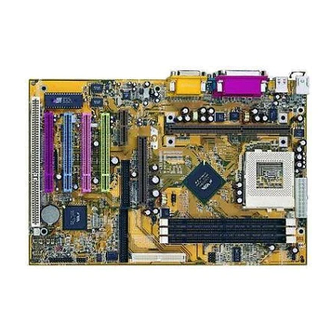
Page 6: The Diagram Of Motherboard
A T X P O W E R C P U F A N D IM M D IM M D IM M P L 1 S L O T -1 U 1 7 J P 2 JP 11 U 1 1 G A M E 8 2 C 4 4 3 B X J P 1 5... -
Page 7: Quick Reference For Jumpers, Connectors & Expansion Socket
Jumper Name Description Page JP11 CPU Type Selection Refer to page 6 p. 6 JP14,JP15 CPU Bus Frequency Selection Refer to page 6 p. 6 CPU Ratio Selector Refer to page 6 p. 6 JP17 CMOS RAM Clear 1-2 Normal ,2-3 Clear CMOS p. -
Page 8: Jumper Settings
2. Install the CPU 3. Install DRAM Modules 4. Install Expansion card Connect Cables, Wires, and Power Supply 2-5 Jumper Settings 1. CPU Type Selection : JP11 Please set JP11 to 1-2 if you are using Slot 1 , Celeron 370 CPU. Please set JP11 to 2-3 if you using Coppermine FC-PGA CPU. -
Page 9: System Memory (Dram)
300/66 66MHz 4.5x 566/66 66MHz 8.5x 500E/100 100MHz 5.0x 333/66 66MHz 5.0x 600/66 66MHz 9.0x 550E/100 100MHz 5.5x 366/66 66MHz 5.5x 600E/100 100MHz 6.0x 633/66 66MHz 9.5x 400/66 66MHz 6.0x 650E/100 100MHz 6.5x 667/66 66MHz 10.0x 466/66 66MHz 7.0x 700/100 100MHz 7.0x 700/66... - Page 10 PART A 2-7-2 The mainboard also provides a 370-pin ZIF Socket 370. The CPU on motherboard must have a fan attached to prevent overheating. To install a CPU, first turn off your system and remove its cover. Locate the ZIF socket and open it by first pulling the lever sideways away from the socket then upwards to a 90-degree right angle.
- Page 11 Reference Design: Heatsink • Intel’s reference design thermal solution is an active heatsink; an extruded aluminum heatsink base and a fan attached to the top on the fin array. • Heatsinks for the PPGA will not work with the FC-PGA. A pedestal is required on the underside of the heatsink to clear the socket FC-PGA with the reference cam box.
- Page 12 CPU Insertion Step 1 Open the socket by raising the actuation lever. Step 2 Insert the processor. Ensure proper pin 1 orientation by aligning the FC-PGA corner marking with the socket corner closest to the actuation arm tip. The pin field is keyed to prevent mis- oriented insertion.
- Page 13 Heatsink Attachment Step 1 Remove the protective liner from the thermal interface material on the underside of the heatsink. This liner is not normally present on the Intel reference active heatsink. Step 2 Orient the heatsink with the keyed edge of heatsink Thumb Tab along the cam box side of the processor.
-
Page 14: Expansion Cards
2-8 Expansion Cards You must read the documentation come with expansion card for any hardware or software settings that may be required to setup your specific card. Installation Procedure: 1. Read the documentation from your expansion card. 2. Set any necessary jumpers on your expansion card. 3. - Page 15 2. PS/2 Mouse & PS/2 Keyboard Connector: MINI-DIN The connectors for PS/2 keyboard and PS/2 Mouse. PS/2 Mouse PS/2 Keyboard 3. USB Port connector: USB The connectors are 4-pins connector that connect USB devices to the system board. USB Port Connector 4.
- Page 16 Pin 1 Floppy drive Connector 7. Primary IDE Connector (40-pin block): IDE1 This connector supports the provided IDE hard disk ribbon cable. After connecting the single plug end to motherboard, connect the two plugs at other end to your hard disk(s). If you install two hard disks, you must configure the second drive to Slave mode by setting its jumpers accordingly.
- Page 17 11. Reset switch lead: RST This 2-pin connector connects to the case-mounted reset switch for rebooting your computer without having to turn off your power switch. This is a preferred method of rebooting in order to prolong the life of the system‘s power supply. See the figure below. 12.
- Page 18 17. Wake On Lan connector: WOL + 5VSB G ND W O N ※ Wake On LAN Function worked only when power supply support 5VSB more than 750mA current. Jumpers & Connectors for motherboard that embedded Audio Chip Only 18. On Board Audio chip Enabled / Disabled connector: JP4 2-3 closed: Enabled 1-2 closed: Disabled 19.
- Page 19 Game / MIDI PORT LINE-OUT LINE-IN Audio and Game Connector 22. PC Speaker signal Input connector: SPKIN 1 SPKIN 1 23. SPDIF (Sony / Philips Digital Interface) Input / Output Connectors: SPDIFIN 1 / SPDIFOUT SPDIFOUT SPDIFIN SPDIFOUT SPDIFIN 1 24.
-
Page 20: Award Bios Setup
AWARD BIOS SETUP This motherboard has previously set to its best stable status. If you are not an experienced user, please do not change the default setting. When you are encounter any problem, please choice “LOAD STANDARD DEFAULTS” to restore best setting. Award’s ROM BIOS provides a built-in Setup program which allows user modify the basic system configuration and hardware parameters. -
Page 21: Standard Cmos Setup
STANDARD CMOS SETUP (Figure 3-1) allows user to configure system setting such as current date and time, type of hard disk drive installed in the system, floppy drive type, and the type of display monitor. Memory size is auto-detected by the BIOS and displayed for your reference. When a field is highlighted (direction keys to move cursor and <Enter>... -
Page 22: Chipset Features Setup
Virus Warning : Disabled PCI/VGA Palette Snoop : Disabled CPU Internal Cache : Enabled OS Select For DRAM > 64MB : Non-OS2 External Cache : Enabled HDD S.M.A.R.T Capability : Disabled Quick Power On Self Test : Disabled Report NO FDD WIN 95 : Disabled Boot Sequence : A,C,SCSI... -
Page 23: Power Management Setup
Auto Configuration : Enabled Auto Detect DIMM/PCI Clk : Enabled DRAM Speed Selection : 60 ns Spread Spectrum Modulated: Disabled EDO CASx# MA Wait Srate CPU Host/PCI Clock : Default EDO RASx# Wait State Warnung Temperature : Disabled SDRAM RAS-to-CAS Delay : 44 °... - Page 24 Power Management : Disabled IRQ 8 Break Suspend : Disabled PM Control by APM : Yes ** Reload Global Timer Events ** Video Off Method : V/H SYNC+Blank IRQ [3-7, 9-15], NMI : Enabled Video Off After : Stand by Primary IDE 0 : Disabled MODEM Use IRQ...
-
Page 25: Pnp/Pci Configuration Setup
• MODEM Use IRQ: Name the interrupt request (IRQ) line assigned to the modem (if any) on your system. Activity of the selected IRQ always awakens the system. The choices: NA, 3, 4, 5, 7, 9, 10, 11 • PM Timer: The following four modes are Green PC power saving functions which are only user configurable when User Defined Power Management has been selected see above for available selections. -
Page 26: Load Optimal Defaults
ROM PCI/ISA BIOS (2A69KJ1L) PNP/PCI CONFIGURATION SETUP AWARD SOFTWARE, INC. PNP OS Installed : No Slot 1 Use IRQ NO : AUTO Resources Controlled By : Manual Slot 2 Use IRQ NO : AUTO Reset Configuration Data: Disabled Slot 3 Use IRQ NO : AUTO IRQ-3 assigned to : Legacy ISA... -
Page 27: Load Standard Defaults
The “LOAD STANDARD DEFAULTS” function loads the system Standard default data directly from ROM and initialize associated hardware properly. This function will be necessary only when the system CMOS data is corrupted. ROM PCI/ISA BIOS (2A69KJ1L) CMOS SETUP UTILITY AWARD SOFTWARE, INC. STANDARD CMOS SETUP INTEGRATED PERIPHERALS BIOS FEATURES SETUP... -
Page 28: Supervisor/User Password
This item lets you configure the system so that a password is required each time the system boots or an attempt is made to enter the Setup program (Refer to Figure 3-3 for the details). Supervisor Password allows you to change all CMOS settings but the User Password setting doesn’t have this function. - Page 29 embedded PC Health Chip PC Health Monitor-III Software for Windows 95/98 Please Run X:\INTEL\HEALTH3\SETUP.EXE NOTES 1. For Windows 95 user:You must run SETUP.EXE twice in order to complete this installation. The computer will install device identification at first time when you run SETUP.EXE. When you finish, you need re-start your computer manually and run SETUP.EXE once again to install correspond driver.
- Page 30 -12V Low Limit/High Limit These values are used to specify the threshold values of detecting the abnormal condition of , 3.3V, +5V, +12V, -12V. 2. FAN Speed CPUFAN/ SYSFAN If the fan RPM is lower than this value and “CPUFAN/SYSFAN” is enabled in Monitoring Config. the PC Speaker will alarm and the monitor software will pop up a window to inform user.
-
Page 31: Pc Health Monitor-Iii Driver ( Option For Mainboard That Embedded Pc Health Chip) 27 4-2 Sound Driver (Option For Mainboard That Embedded Audio Chip)
and four channel speakers mode. Support Windows 3.1 / 95 / 98 and Windows NT 4.0. Built-in 32 OHM Earphone buffer and 3D surround. MPU-401 Game/Midi port and legacy audio SB16 support. Downloadable Wave Table Synthesizer, supports Direct Music®. • Digital Audio (SPDIF IN/OUT) Up to 24 bit stereo 44KHz sampling rate voice playback/recording. - Page 32 CMI8738/C3DX PCI Audio Joystick Device CMI8738/C3DX PCI Audio Legacy Device DOS mode MPU-401 Emulator 8. Install Application Software : Click “start” key 9. Select “Run” 10. Key in the drive and path for Windows application installation program, for example, in Win95 “X:\CMI8738\Win9X\APP\Win95\SETUP.EXE” in Win98 “X:\CMI8738\Win9X\APP\Win98\SETUP.EXE”...
- Page 33 12. Select “Run” item. 13. Key in drive and path for Windows NT application installation program, for example, “X:\CMI8738\NT40\APP\SETUP.EXE” 14. Click “OK” to start the installation procedure, and follow the on-screen instructions to finish the installation. When all of application softwares have been installed, shut down the Windows NT system, and then reboot your system.
- Page 34 MIDI Player, Wave Player, and CD Player CD Player (above, similar to Wave Player and MIDI Player) Sel (or Trk) fielX: If you have multiple selections in your playlist, this shows the number of the current selection or CD track. Current File or Track: The name of the current MIDI file, wave audio file, or CD track.
- Page 35 • FM: Controls the FM music playback or the recording level. • Aux-in: Controls the Aux-in music play or the recording level. • PC-SPK: Controls the external PC speaker input level. • CX: Controls the CD drive output level, for CD drives configured to play their audio output through the PC’s audio hardware.
- Page 36 Optical Module Optical Cable Software DVD drvier OPTICAL MODULE J1:SPDIF-IN DIP-SWITCH OPTICAL OUT OPTICAL IN An example of optical kit is used to connect motherboard and the MD. The application program setup(please install CMI8738 application program first) When the connection is done, please go to the Start menu and select PCI Audio Applications\Audio Environment Setting...
- Page 37 When all the procedures have been completed, there will be an infrared signal coming from the SPDIF/OUT of the optical fiber of the sound card.
- Page 38 Please note that signal beam may cause severe damage to the eyes. For your safety, please point the output end to a piece of white paper to check if the beam is in function. Please connect the output signal to the MD input, then play the music via the MP3 player:...
- Page 39 Please note that in playback, if there is no gap longer than three seconds between each track, the MD can not recognize the tracks and will record all of them into one. It is recommended that you set the gap time to 3~5 seconds to meet all type of MD requirements.
- Page 40 About Recording 24bit Audio Setting 24-bit audio can only be applied to SPDIF IN/OUT mode; it does not apply to other modes such as the four channels or the analog. No sound will be heard while in playback, yet it can be recorded.
- Page 41 The un-selected area will be gray out. The un-selected area will be gray out. You can double-click this circuit icon to have the following setting box. By means of this setting box, you can also complete the above-mentioned setting procedures.
- Page 42 THE SPDIF/IN An example of Portable CD Player(Output) to optional Optical Kit (Optical Input)Setup...
- Page 43 When the connection is done, please go to the Start menu and select PCI Audio Applications\Audio Environment Setting...
- Page 44 Loopback(bypass)mode setup CD ROM (Digital Output) to optional Optical Kit (SPDIF/IN)Setup...
- Page 45 When the connection is done, please go to the Start menu and select PCI Audio Applications\Audio Environment Setting Please follow these setting procedures.
- Page 46 Now you can insert the CD into the CD ROM drive, then activate C-MEDIA CD player and push the ”play” button to do the recording job. Please note that you have to set the MD in the simultaneous-recording mode.
-
Page 47: Quick Troubleshooting Guide
Chapter 5 Quick Troubleshooting Guide If the result of your diagnostic is “call service”, please have the following information ready before you contact for any technical support. 1. The CPU (Central Processing Unit) you are using along with its require setting. 2. -
Page 48: Frequently Asked Questions And Answers
1. You must have CBROM.EXE file (You can find it from Driver Pack CD or download it from our website at www.jetway.com.tw). 2. Make your own logo file by “Bitmap” format. The dimension limit is 640 x 464 x 16 color.