Table of Contents
Advertisement
531CF
USER'S MANUAL
3D AGP VGA / 3D Audio M/B
FOR Pentium
processor
The author assumes no responsibility for any errors or omissions which
may appear in this document nor does it make a commitment to update
the information contained herein.
NO. G03-531CFR6A
Release date: SEP 2000
** Year 2000 compliant **
Trademark:
*Pentium is registered trademark and MMX is a trademark of Intel corporation,
the other names and brands are the property of their respective owners.
*Specifications and Information contained in this documentation are furnished for information use only, and are
subject to change at any time without notice, and should not be construed as a commitment by manufacturer.
Advertisement
Table of Contents

Related Manuals for JETWAY 531CF-6


Summary of Contents for JETWAY 531CF-6
- Page 1 531CF USER'S MANUAL 3D AGP VGA / 3D Audio M/B FOR Pentium processor The author assumes no responsibility for any errors or omissions which may appear in this document nor does it make a commitment to update the information contained herein. NO.
-
Page 2: Table Of Contents
TABLE OF CONTENT Chapter 1 1-1 Preface ..................1-2 Orerview ................................... Key Feature Chapter 2 Hardware lnstallation ................2-1 Unpacking ..................2-2 Mainboard Layout ................4 .... Quick Reference for Jumpers, Connectors & Expansion Socket ..............2-3-1 lnstallation Steps .............. -
Page 3: Preface
Chapter 1 Preface 2-3- Thank you for chosen 531CF mainboard. This mainboard is based on Pentium® processor PC/AT compatible system with ISA bus and PCI local bus. This board has including some special designs, such as share memory 3D AGP VGA on-board, 3D Stereo Sound System audio chip on-board, ACPI/APM power management along with many other powerful features. -
Page 4: Key Feature
1-3 Key Feature • Multi-Speed Support : support 66/75/83/95/100MHz Host Bus Frequency for Intel Pentium processor with MMX technology ,AMD K5/K6/K6-2/K6-3,Cyrix 6x86 M1/M2,IDT Winchip/ Winchip2 CPU on a ZIF Socket7. • Chipset: SiS 530/5595 AGPset chip with I/O subsystems and CMI 8738 PCI Audio chip. •... -
Page 5: Hardware Lnstallation
Chapter 2 Hardware Installation Unpacking 2-3- This mainboard package should contain the following: • 531CF mainboard • USER’S MANUAL for mainboard • Cable set for IDE x1, Floppy x1,COM x1 • CD for Drivers PACK The mainboard contains sensitive electronic components that can be easily damaged by electron- static, so the mainboard should be left in its original packing until it is installed. -
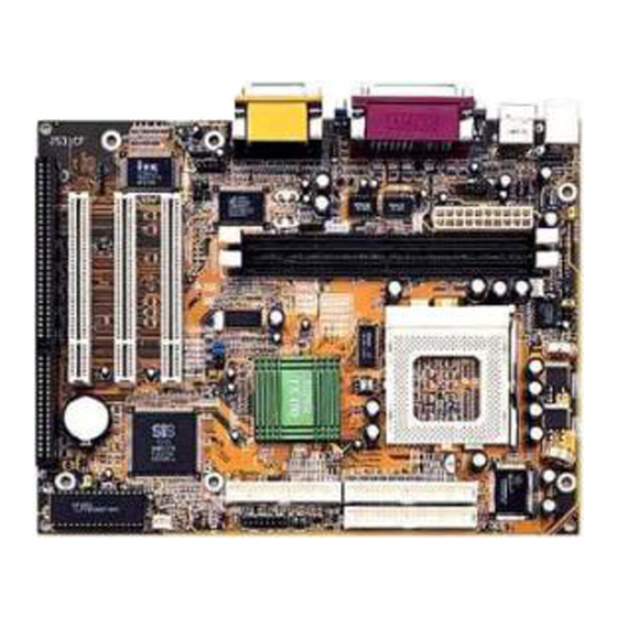
Page 6: Mainboard Layout
Mainboard Layout 2-3- JP 5 JP 9 U 15 P W 1 64K X64 U S B C P U -F A N C O M1 W O L V G A 1 32K X8 JP 11 U 12 S IS 530 SP D IF IN U 17 JP 10... -
Page 7: Quick Reference For Jumpers, Connectors & Expansion Socket
Quick Reference for Jumpers, Connectors & 2-3- Expansion Socket Jumpers Jumper Name Description Page CPU Voltage Selection ON:Short , OFF:Open p. 6 JP10,JP11 CPU Bus Frequency Selection ON:Short , OFF:Open p. 6 JP12 CMOS RAM Clear 2-3 Normal , 1-2 Clear CMOS p. -
Page 8: Lnstallation Steps
2-3-1 Installation Steps Before using your computer, you must follow the steps as follows: 1. Set Jumpers on the Motherboard 2. Install the CPU 3. Install DRAM Modules 4. Install Expansion card 5. Connect Cables, Wires, and Power Supply 2-3-2 Jumper Settings CPU Voltage Selection: JP9 (2x5pin Block) This jumper is used for adjusting CPU working voltage, for this main board design it can auto... - Page 9 CPU Bus Clock SDRAM Clock PCI Clock 66 MHz 100 MHz 75 MHz 100 MHz 112 MHz 112 MHz 74 MHz 112 MHz 124 MHz 124 MHz 124 MHz 82 MHz 133 MHz 133 MHz 133 MHz 89 MHz ¡ ° SDRAM Clock Asynchronous as CPU Bus frequency let user can use slow speed SDRAM when CPU clock over 83MHz.
-
Page 10: System Memory (Dram)
NOTE: 1. Before installing the CPU, Please check the CPU Frequency and Clock Ratio from your supplier. 2. For Cyrix/IBM 6X86MX series, please double check the CPU’s Frequency and Clock Ratio. 1. CMOS RAM: JP12 (Yellow color selector) WARNING: Make sure your computer is POWER OFF when you are CLEAR CMOS. Connect a jumper Cap over this jumper for a few seconds, will clears information stored in the CMOS RAM Chip that input by user, such as hard disk information and passwords. -
Page 11: Expansion Cards
IMPORTANT: You must set jumpers JP10,JP11 “CPU Type selector” on page 6 and jumper JP9 “CPU Voltage Selection” on page 6 depending on the CPU that you install. Lever White Dot Lock Blank CPU ZIF Socket 7 2-5 Expansion Cards First read your expansion card documentation on any hardware and software settings that may be required to setup your specific card. - Page 12 The PS/2 Keyboard is a 6-pin miniature DIN connector. It is for a standard PS/2 style keyboard. May also be known as a 101 enhanced keyboard. The PS/2 Mouse connector is a similar 6-pin, miniature DIN connector. PS/2 Mouse PS/2 Keyboard 3.
- Page 13 6. Audio and Game Connector : GAME PORT This Connector are 3 phone Jack for LINE-OUT,LINE-IN,MIC and a 15-pin D-Subminiature Receptacle Connector for joystick/MIDI Device. Line-out : audio output to speaker Line-in : audio input to sound chip MIC : Microphone Connector Game/MIDI : for joystick or MIDI Device G a m e / M ID I P O R T L IN E -O U T...
- Page 14 P i n 1 S e c o n d a r y I D E C o n n e c t o r 10. IDE activity LED: HDLED This connector connects to the hard disk activity indicator light on the case. IDE (Hard Drive) LED 11.
- Page 15 IR 1 Infrared Module Connector 16. USB Port connector: USB The connectors are 4-pins connector that connect USB devices to the system board. USB Port Connector 17. CPU FAN connector: CPUFAN CPUFAN +12V R.P.M. SENCE CPU Fan Connector 18. Extra fanning system connectors: SYSFAN SYSFAN +12V R.P.M.
- Page 16 20. CD Audio in connector : JP6 JP7 These two connectors are design for two type of CD-ROM output cable. Panasonic Compatible Sony Compatible CD-ROM Audio connector 21. On board sound chip Enbled / Disabled connector : JP3 1-2 Closed: Disabled 2-3 Closed: Enabled (Default) 22.
- Page 17 SPDIFIN SPDIFIN 26. SPDIFOUT (Sony / Philips Digital lnterface ) Connectors : SPDIFOUT SPDIFOUT SPDIFOUT 27.Opticl kit connector :JP2 28.Keyboard Power on Selection Connector :JP5 1-2 Close : Disabled 2-3 Close : Enabled Chapter 3...
-
Page 18: Award Bios Setup
AWARD BIOS SETUP This motherboard has previously set to its best stable status. If you are not an experienced user, please do not change the default setting. When you are encounter any problem, please choice “LOAD STANDARD DEFAULTS” to restore best setting. Award's ROM BIOS provides a built-in Setup program which allows user modify the basic system configuration and hardware parameters. -
Page 19: Bios Features Setup
Choose "STANDARD CMOS SETUP" in the CMOS SETUP UTILITY Menu (Figure 3-1). The STANDARD CMOS SETUP allows user to configure system setting such as current date and time, type of hard disk drive installed in the system, floppy drive type, and the type of display monitor. Memory size is auto-detected by the BIOS and displayed for your reference. -
Page 20: Chipset Features Setup
Select the "BIOS FEATURES SETUP" option in the CMOS SETUP UTILITY menu allows user to change system related parameters in the displayed menu. This menu shows all of the manufacturer's default values of this motherboard. Again, user can move the cursor by pressing direction keys and <PgDn>... -
Page 21: Power Management Setup
chipset, this section will bear little resemblance to what you see on your screen. ADVANCED OPTIONS. The parameters in this screen are for system designers, service personnel, and technically competent users only. Do not reset these values unless you understand the consequences of your changes. ROM PCI/ISA BIOS (2A5IMJ1A) CHIPSET FEATURES SETUP AWARD SOFTWARE ,INC... - Page 22 The Power Management Setup allows you to configure you system to most effectively save energy while operating in a manner consistent with your own style of computer use. ROM PCI/ISA BIOS (2A5IMJ1A) POWER MANAGEMENT SETUP AWARD SOFTWARE, INC. ACPI function : Enabled VGA Activity : Enabled...
- Page 23 • PM Timers : The following four modes are Green PC power saving functions which are only user configurable when User Defined Power Management has been selected. See above for available selections. • HDD Off After : By default, this item is Disabled, meaning that no matter the mode the rest of the system, the hard drive will remain ready.
-
Page 24: The Description Of The Power Management
3-4-1 The Description of the Power Management • Power Management mode selection: User Define: This category allows you to select the type (or degree) of power saving and is directly related to the following modes: 1. HDD Power Down 2. Doze Mode 3. -
Page 25: Description Of The Green Functions
standard of the Video Electronics Standards to select video power management values. • PM Monitors: The following four modes are Green PC power saving functions which are only user configurable when User Defined Power Management has been selected. See above for available selections. HDD Power Down: When enabled and after the set time of system inactivity, the hard disk drive will be powered down while all other devices remain active. -
Page 26: Pnp/Pci Configuration Setup
When the system suspend timer time out, the system will enter the suspend mode and the chipset will stop CPU clock immediately. The power consunption in Suspend Mode is lower than in standby mode. The screen is also blanked out. PM Events: AWARD BIOS defines 15 PM Events in the power management mode (Doze, standby &... -
Page 27: Load Optimal Defaults
3-6 LOAD OPTIMAL DEFAULTS The "LOAD OPTIMAL DEFAULTS" function loads the system default data directly from ROM and initialize associated hardware properly. This function will be necessary only when the system CMOS data is corrupted. ROM PCI/ISA BIOS (2A5IMJ1A) CMOS SETUP UTILITY AWARD SOFTWARE, INC. -
Page 28: Integrated Peripherals Setup
3-8 INTEGRATED PERIPHERALS SETUP The “INTEGRATED PERIPHERALS SETUP” mainly deals with I/O function. This function will be necessary only when the system I/O malfunctioned or the system is unable to detects your CD-ROM or hard disk. ROM PCI/ISA BIOS (2A5IMJ1A) INTEGRATED PERIPHERALS AWARD SOFTWARE, INC. -
Page 29: Exit Without Saving
The "SAVE & EXIT SETUP" option will bring you back to boot up procedure with all the changes you just made which are recorded in the CMOS RAM. 3-11 EXIT WITHOUT SAVING The "EXIT WITHOUT SAVING" option will bring you back to normal boot up procedure without saving any data into CMOS RAM. -
Page 30: On Board Vga Driver Quick Installation
4-1 On Board VGA Driver Quick Installation WINDOWS 95/98/98SE Display Driver Quick Installation Step 1. Before Install the driver please view the “readme” file. Step 2. Run “X:\SiS530\VGA\WIN9X\SETUP.EXE” (if your CD-ROM is X drive) Step 3. Follow the setup procedure install your VGA Driver. WINDOWS NT4.0 Display Driver Quick Installation Step 1. - Page 31 • Stereo Mixer and FM Music Synthesizer Stereo analog mixing from CD-Audio, Line-in Stereo digital mixing from Voice, FM/Wave-table, Digital CD-Audio Mono mixing from MIC and software adjustable volume OPL3 FM synthesizer (4 operators) Up to 15 melody sounds and 5 rhythm sounds (20 voices) •...
- Page 32 in Win98 “X:\CMI8738\Win9X\APP\Win98\SETUP.EXE” 11. Click “OK” to start the installation procedure, and follow the on-screen instructions to finish the installation. When all the application softwares have been installed, please shut down Windows 95/98 system, and reboot your system. Win95/98/98SE Un-Installation If you install Win95/98 and a sound card at the same time, you might experience some technical difficulties(the device might not function properly).
- Page 33 By means of a user-friendly interface(as easy as operating your home stereo system), this PCI audio rack provides you with the control over your PC’s audio functions, including the advantage of four speakers mode enable/ disable, and perfect digital sound ( SPDIF ) input / output control. This Audio Rack consists of several major components: Control Center: Controls the display of the PCI Audio Rack’s components.
- Page 34 Current File or Track: The name of the current MIDI file, wave audio file, or CD track. Total Length fielX: displays the total length of files or tracks in minutes and seconds. Current Time fielX: displays the current time of files or tracks in minutes and seconds when playback or recording.
- Page 35 • SurrounX: Turn on or turn off the 3D surround sound effect. • SPDIF-in: Turn on or turn off the SPDIF digital signal input. Mute Buttons: Toggle between muting and enabling the signal. A button with a lit LED is enabled, and when it is not lit, it means it is mute.
- Page 36 An example of optical kit is used to connect the sound card and the MD. The application program setup(please install CMI8738 application program first) When the connection is done, please go to the Start menu and select PCI Audio Applications\Audio Environment Setting...
- Page 37 When all the procedures have been completed, there will be an infrared signal coming from the SPDIF/OUT of the optical fiber of the sound card.
- Page 38 Please note that signal beam may cause severe damage to the eyes. For your safety, please point the output end to a piece of white paper to check if thebeam is in function. Please connect the output signal to the MD input, then play the music via the MP3 player:...
- Page 39 Please note that in playback, if there is no gap longer than three seconds between each track, the MD can not recognize the tracks and will record all of them into one. It is recommended that you set the gap time to 3~5 seconds to meet all type of MD requirements.
- Page 40 About Recording 24bit Audio Setting 24-bit audio can only be applied to SPDIF IN/OUT mode; it does not apply to other modes such as the four channels or the analog. No sound will be heard while in playback, yet it can be recrded.
- Page 41 The un-selected area will be gray out. The un-selected area will be gray out.
- Page 42 The un-selected area will be gray out. You can double-click this circuit icon to have the following setting box. By means of this setting box, you can also complete the above-mentioned setting procedures. 531CF SPDIF/IN An example of Portable CD Player(Output) to 531CF(Optical Input)Setup...
- Page 43 When the connection is done, please go to the Start menu and select PCI Audio Applications\Audio Environment Setting...
- Page 44 3.Loopback(bypass)mode setup CD ROM (Digital Output) to 531CF (SPDIF/IN)Setup...
- Page 45 When the connection is done, please go to the Start menu and select PCI Audio Applications\Audio Environment Setting Please follow these setting procedures.
- Page 46 Now you can insert the CD into the CD ROM drive, then activate C-MEDIA CD player and push the ”play” button to do the recording job. Please note that you have to set the MD in the simultaneous-recording mode.