Table of Contents
Advertisement
Quick Links
Advertisement
Table of Contents

Related Manuals for TCS Carus Origo CAI2010


Summary of Contents for TCS Carus Origo CAI2010
- Page 1 Product information video indoor station Carus Origo CAI2000, CAI2010...
-
Page 2: Table Of Contents
Table of contents Scope of delivery .................. 4 Safety instructions ................4 General safety regulations ..............4 Installation – protective measures ............4 Terms ..................... 5 Technical data ..................5 Device overview ..................6 Indication and operating elements ............7 Intended use .................. - Page 3 Select the camera by stepping with the image button ......32 Short messages .................. 32 Read short messages ..............32 Delete short messages ..............33 General information on the conduit in TCS video systems ....33 6-wire operation .................. 33 Principle loop resistance ..............34 Measurement loop resistance ............34 Repair ....................
-
Page 4: Scope Of Delivery
When working on main power connections of 230V AC, the general and regional installation and safety regulations must be met. i.e. DIN VDE 0100 TCS:BUS system installations must be in compliance with the general safety regulations for telecommunication systems according to VDE 0800. Including: ... -
Page 5: Terms
Terms Main door call Door call from the door with the main serial number (according to the serial number sticker on the device and the packaging). Two main door calls from front- door stations with AS = 0 and AS > 0 can be distin- guished. -
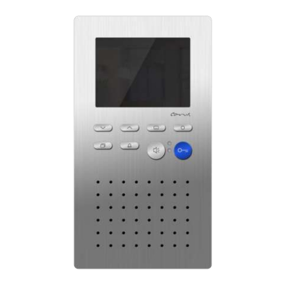
Page 6: Device Overview
Device overview screen menu button navigation function key button UP navigation LED indica- button DOWN tion, red image door release button button call OFF- button LED indication, green speech button loudspeaker microphone... -
Page 7: Indication And Operating Elements
Indication and operating elements Term Function display the video image screen display ring tone parameter and image pa- rameter via OSD speech button call acceptance, activate speaking, simplex communication end communication door release (factory setting) door release ... -
Page 8: Intended Use
Intended use CAI20x0 are video indoor stations with color display for hands-free talking and simplex communication. They can be used for the opera- tion within building communication systems and combined audio-video systems. The CAI20x0 are operated by pressing the keys and via the On- Screen-Display. -
Page 9: Short Description
Short description hands-free talking, manually controlled simplex communication can be activated blue door release button button for call acceptance resp. reversing key speak/listen, when sim- plex communication is activated one function key (ex works allocated with control function; with alterna- tive allocation: internal call, door release automatic, call diversion, light switch function, control function;... -
Page 10: Installation
Installation Installation CAI2000 (wall mounting) Attention! The video indoor stations have to be (de-)installed only voltage-free! Ensure not to over tighten the screws when installing the wall adapter plate on uneven surfaces. Otherwise the plate might be deformed. Install the adapter plate For an optimal operation a mounting height of 1.6 m is recommended. -
Page 11: Connect The Lines
Connect the lines acceptable cross-section (di- 0.08 … 0.82 mm (Ø 0.32 … 1.0 mm) ameter) max. number of wires per each 2 x 0.8 mm, 3 x 0.6 mm terminal contact Further wires have to be connected via auxiliar terminals! ... -
Page 12: Snapping-On The Top Shell
Snapping-on the top shell Position the top shell at both adjustment brackets of the bottom shell (1). Snap-in the top shell below with slight pressure (2). Open the device There is a rectangular release opening at the bottom of the device (3). Insert a small screwdriver straight and with slight pres- sure into this opening. -
Page 13: Installation Cai2010 (Tabletop Device)
Installation CAI2010 (tabletop device) Attention! The video indoor stations have to be (de-)installed only voltage-free! The table rack is pre-configured and has to be connected to a RJ45 socket. Therefore please note the connection diagram under cable as- signment. In delivery state the device is equipped with a terminating resistor be- tween V1 and V2. -
Page 14: Cable Assignment
Cable assignment Wires Connect to Plug PIN no. connection termi- orange green- white blue blue-white green brown- white brown Terminating resistor CAI2010 Observe when installing video tabletop devices: The installation of the lines to the connection sockets must be realised star-shaped and must NOT be looped through. -
Page 15: Deinstall The Device
Deinstall the device There is a rectangular release opening at the bottom of the device (1). Insert a small screwdriver straight and with slight pressure into this opening. The screw driver must not be wider than 7 mm and thicker than 2 mm. -
Page 16: Wiring Diagram
Wiring diagram Set terminating resistor if the device is installed at the end of the TCS:BUS video strand. Connection diagram... -
Page 17: 5-Wire Special Operation
5-wire special operation In case that only 5 lines are available to connect the device and the M-wire cannot be connected, you can use the device in 5-wire special operation. Installing a wire bridge between the wires b and M is only permitted when observing some conditions.. -
Page 18: Settings
Note: The AS-addresses of the front-door stations have to be assigned via the Service Device. For detailed information see section Service information in the TCS Installer 5 / 4 (Version 1) or TCS Installer 7 / 4 (Version 2). The device is equipped with am EEPROM which stores the following fac-... -
Page 19: Configuration Options
Configuration options configo manual- Function TCSK-01 as of version 1.7.x – – fixed simplex communication simplex communication to the front-door – – station – menu ring tone volume ring tones for front-door calls, internal calls – menu and floor calls –... -
Page 20: General Information On The Osd Menu
internal call control function 8 light switch function parallel allocation Note: Deactivation of the parallel alloca- tion corresponds to the parallel alloca- tion to serial number 0. ser. no. = the serial number of the indoor station that is to be configured new TarSerNo. -
Page 21: Symbols And Their Meaning
Main menu selected parameter symbol main menu symbol of the selected menu Indication empty storage Symbols and their meaning sym- meaning sym- meaning ring tone button for door calls <= indication of adjusted values as 0...9 AS-border numbers ring tone selection for door calls symbol for call setup menu <= AS-border image buffer;... -
Page 22: Help Function
screen to read a short mes- ring tone volume sage* contrast setting delete short messages* brightness setting date setting* color saturation setting time setting* delete image buffer (all stored symbol camera for fading-in the images) * AS-address ... -
Page 23: Internal Calls And Control Functions
Internal calls and control functions The plain texts, which should appear in the selection menu, can be set with the configuration software configo™. Internal call destinations or con- trol processes can be entered there as plain text. 10 internal calls and 10 control functions can be sent via the OSD menu. Simple Each triggering sends the same control protocol. -
Page 24: Send Internal Call
Press the menu button. Select the sym- bol Send control function Or call up the menu with the function key when the device is configured appropriately. Select the required function with the nav- igation buttons UP or DOWN. ... -
Page 25: External Image Buffer
External image buffer (not included in the delivery) Images or image sequences can be stored with the external image buffer FVM1000. The number of images is limited to 64 per device. The oldest image is overwritten. Ensure, that the video indoor station CAI20x0 is ready for operation. -
Page 26: Store Images Manually
Store images manually When the image is activated, an image can be stored manually. Shortly press the navigation button UP. A symbol is faded-in with date, time and number and indicates the successful storage. The green LED is blinking until the image has been viewed. View stored images When the green LED blinks, new imag- es were stored:... -
Page 27: Delete All Stored Images
Delete all stored images In the image buffer all stored images, allocated to the indoor station, can be deleted. Press the menu button. The main menu is displayed. Select the symbol Delete image buffer Confirm the selection by pressing the menu button. -
Page 28: Set The Ring Tone Volume
Set the ring tone volume Press the navigation button UP (or DOWN), the symbol ring tone volume is pre-selected. Press the navigation button UP or contrast DOWN to adjust the volume. The level of the ring tone volume (1 to 4) is displayed. -
Page 29: Set The Conversation Volume
Set the conversation volume ... in case of a voice connection to the door: Press the menu button during a voice connection. The menu to set the im- age parameter and the symbol for conversation volume setting are dis- played. -
Page 30: Set Date And Time Of The Image Buffer
Set date and time of the image buffer (not included in the delivery) This dialog only appears when the use of an external image buffer and the permission to set date and time has been set in the EEPROM. Press the menu button. The main menu is displayed. -
Page 31: Set Image Parameter
Set image parameter Symbols in the live image: The symbols in the live image are faded- in for 10 sec by activating the image (after the image button was pressed or a door call has been received) or for 3 sec after pressing the speech button. -
Page 32: Reload Factory Settings
Short messages The video indoor station CAI20x0 can receive short messages via the TCS:BUS. The messages can be stored and displayed. Max. 10 short messages can be stored. The received message can include max. 95 characters. -
Page 33: Delete Short Messages
General information on the conduit in TCS video systems 6-wire operation 6-wire operation is the standard operation mode. Video operation, where two separated masses (b and M) are used. -
Page 34: Principle Loop Resistance
Do not use more than 20 indoor stations per strand. For systems with more video indoor stations plan to use video distributors (FVY1200, FVY1400). Up to 64 front-door stations (16 of them video front-door stations) and almost an unlimited number of indoor stations can be connected within one system polarity-free (a/b;... -
Page 35: Repair
8 Ohm: AS front-door station, around 65 m distance AS-VS by 0.6 VS power supply and control unit, mm diameter around 115 m distance AS-VS by 0.8 IS indoor station, FE extended function mm diameter Repair Repairs have to be carried out only by qualified electricians. Error pattern Possible cause Our suggested solution... - Page 36 The level of the video Turn down the level of the video signal is too high. bus (e.g. rotary control on the board of the camera). This only works, when the terminating resis- tor is placed correctly at the sta- tion or active extended functions (e.g.
- Page 37 Contours of a second Two video sources Please remove the second video image are visible. interfere. source from the strand. Connect the second video source, if necessary, via a video switch to the existing TCS:BUS.
- Page 38 No image. When press- No signal present. Connect the monitor before the ing the image button video switch and check if there is there is no respond. a signal. Measure the voltage between P and b. The voltage value is around 26 V. If this is not the case, check the BUS voltage supply.
-
Page 39: Cleaning
Cleaning Avoid water from entering the device! Do not use any abrasive detergents! Clean the indoor station with a dry or slightly wet cloth. Remove stronger stains with a pH-neutral cleaner. Conformity Declarations of conformity for download under www.tcsag.de > Downloads >... -
Page 40: Service
Service Please send your questions and inquiries to hotline@tcsag.de Headquarters Subject to technical changes. TCS TürControlSysteme AG Geschwister-Scholl-Str. 7, 39307 Genthin TCS Hotline Germany FON: +49 3933 8799-10, FAX: +49 3933-8799-11 FON: +49 4194 9881-188, FAX: +49 4194 9881-29 E-Mail: info@tcsag.de, www.tcsag.de E-Mail: hotline@tcsag.de...