Table of Contents

Related Manuals for Nortel Secure Router 3120


Summary of Contents for Nortel Secure Router 3120
- Page 1 Secure Router 3120 Installation Guide ATTENTION Clicking on a PDF hyperlink takes you to the appropriate page. If necessary, scroll up or down the page to see the beginning of the referenced section. NN47260-300 (321996-B)
- Page 2 In the interest of improving internal design, operational function, and/or reliability, Nortel Networks reserves the right to make changes to the products described in this document without notice. Nortel Networks does not assume any liability that may occur due to the use or application of the product(s) or circuit layout(s) described herein.
- Page 3 International Regulatory Statements of Conformity This is to certify that the Nortel Secure Router 3120 Series products are evaluated to the international regulatory standards for electromagnetic compliance (EMC) and safety and was found to have met the requirements for the following international standards: •...
- Page 4 CE marking statement (Europe only) EN 55022 statement This is to certify that the Nortel Secure Router 3120 series products are shielded against the generation of radio interference in accordance with the application of Council Directive 89/336/EEC. Conformity is declared by the application of EN 55022 Class A (CISPR 22).
- Page 5 Observe the Regulatory Marking label on the back or bottom of each switch for specific certification information pertaining to this model. Each model in the Nortel Secure Router 3120 Series is approved for shipment to/usage in Korea and is labeled as such, with all appropriate text and the appropriate MIC reference number.
- Page 6 Denan statement (Japan/Nippon only) Nortel Networks software license agreement This Software License Agreement ("License Agreement") is between you, the end-user ("Customer") and Nortel Networks Corporation and its subsidiaries and affiliates ("Nortel Networks"). PLEASE READ THE FOLLOWING CAREFULLY. YOU MUST ACCEPT THESE LICENSE TERMS IN ORDER TO DOWNLOAD AND/OR USE THE...
- Page 7 (such as images, text, recordings or pictures) and related licensed materials including all whole or partial copies. Nortel Networks grants you a license to use the Software only in the country where you acquired the Software. You obtain no rights other than those granted to you under this License Agreement. You are responsible for the selection of the Software and for the installation of, use of, and results obtained from the Software.
- Page 8 Getting help over the phone from a Nortel Solutions Center If you do not find the information you require on the Nortel Technical Support web site, and have a Nortel support contract, you can also get help over the phone from a Nortel Solutions Center.
-
Page 9: Table Of Contents
Site Safety 20 Power Requirements 20 Network Connection 21 Equipment Rack 21 Tools and Materials 22 Unpacking the Secure Router 3120 23 Mounting the Secure Router 3120 24 Surface Mount 24 Rack Mount 24 Secure Router 3120 Power 26 DC Power 26... - Page 10 Serial/PPP Bundle 60 Serial/Cisco-compatible HDLC Bundle 61 Routing Configuration 61 Compact Flash Configuration 63 Saving Configurations 64 TROUBLESHOOTING Alarms and Secure Router 3120 Status 65 WAN Statistics 66 Power Supply Alarms 66 Network Tests 66 Ping Test 67 T1 Tests 67...
-
Page 11: Contents
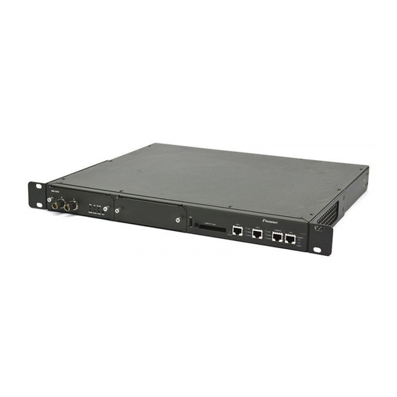
Class A device Caution statement 103 Qualified service personnel warning statement 104 Overcurrent warning statement 105 Index Figures Figure Secure Router 3120 Front Panel (Modules shown are 4-port module and 8-port module) 17 Figure 3120 Rear Panel 18 Figure Chassis Air Flow 20... -
Page 12: Secure Router 3120
Table Pinouts: EIA/TIA-449 (RS-449) DCE (26 Pin) to DB-37 Connector 89 Table Pinouts: EIA-530 or 530A DTE (26 Pin) to DB-25 Connector 90 Table LEDs: Secure Router 3120 Status 93 Table LEDs: Ethernet Status 93 Table Link Status LEDs 94... -
Page 13: About This Guide
ABOUT THIS GUIDE This chapter provides information about the intended audience for this Nortel Secure Router 3120 guide, how this guide is organized, typographical conventions, the use of notices, and related documentation. This guide is designed for network managers and technicians who are responsible for the installation and administration of networking equipment in Telco and service provider environments. -
Page 14: Conventions
14 ABOUT THIS GUIDE Chapter Description "CONFIGURATION" (page 43) describes powering on the Secure Router 3120, initial configuration, logging in, factory defaults, and changing the default password. "TROUBLESHOOTING" (page 65) provides information about network indicators, tests, and general troubleshooting tips. A summary of common problems and solutions is also included. -
Page 15: Cautions And Warnings
For translations of this statement, see "Qualified service personnel warning statement" (page 104). Secure Router 3120 Installation Guide NN47260-300 02.01 Standard 9.2 10 January 2007 Copyright © 2005-2007, Nortel Networks Nortel Networks Confidential... -
Page 16: Documentation
This user guide explains how to configure Secure Routers using the CLI. • SR3120 Web UI User Guide This user guide explains how to configure Secure Routers using the WebUI. Secure Router 3120 Installation Guide NN47260-300 02.01 Standard 9.2 10 January 2007 Copyright © 2005-2007, Nortel Networks Nortel Networks Confidential... -
Page 17: Product Introduction
This section describes front and back-panel components of the Secure Router 3120. Additional information is also provided about external cables, wiring, and connection points. The Secure Router 3120 comes with single and dual AC, single DC and dual DC, and single AC/single DC power options. Front Panel... -
Page 18: Back Panel
Summary alarm. Indicates a hardware problem (power failure, fan failure, etc.) Power LED Green indicates the Secure Router 3120 has power. Off indicates the Secure Router 3120 is not powered. Back Panel The 3120 rear provides connections for power. There are no maintenance access requirements for the rear panel. -
Page 19: Installation
Site location is important for the proper operation of Secure Router 3120s. Place the unit in a clean, dry environment with adequate air circulation. Allow two to three feet additional clearance around the Secure Router 3120 for access to the cable connectors on the front and rear panels. -
Page 20: Site Safety
Make sure that the site is safe from hazards such as damp or wet floors, improper or missing circuit breakers, poor grounds, etc. • Use two people to lift the Secure Router 3120 chassis when installing the chassis in an equipment rack. •... -
Page 21: Network Connection
19- or 23-inch Telco equipment rack. These Secure Router 3120s can be flush (front), middle, or rear mounted in an equipment rack. Secure Router 3120 Installation Guide NN47260-300 02.01 Standard 9.2 10 January 2007 Copyright © 2005-2007, Nortel Networks Nortel Networks Confidential... -
Page 22: Tools And Materials
The following additional items may be required to install these Secure Router 3120s in your operating environment. This is dependent on Secure Router 3120 configuration and how the Secure Router 3120 will be managed. Cables The following cables may be required for operation of these Secure Router 3120s in your environment. -
Page 23: Unpacking The Secure Router 3120
• Surface-mount package (four self-adhering rubber feet) • Nortel Secure Router CD-ROM Inspect the Secure Router 3120 for damage that may have occurred during shipping. If you discover damage or missing items, contact Nortel Technical Support. Secure Router 3120 Installation Guide NN47260-300 02.01 Standard... -
Page 24: Mounting The Secure Router 3120
Surface Mount Place the Secure Router 3120 on a clean, flat, and stable surface with a minimum available footprint of 12 by 19 inches (30.48 or 48.26 cm). Allow sufficient room at the front, rear, and side of the unit for interface cabling, power cord clearance, and adequate ventilation. -
Page 25: Attaching Mounting Brackets
Note 1: For problem-free operation, the equipment rack should be located in an area with sufficient clearance for cabling and adequate ventilation. Note 2: Attach the mounting brackets to the Secure Router 3120 before securing the Secure Router 3120 to the rack. To attach the mounting brackets:... -
Page 26: Secure Router 3120 Power
—End— Secure Router 3120 Power The Nortel 3120 supports single AC, dual AC, single DC, dual DC or AC/DC power, depending on the ordered configuration. These Secure Router 3120s accept external power from single AC, dual AC, single DC, dual DC, or single AC/single DC sources. - Page 27 Before connecting cables or performing maintenance on a Secure Router 3120, always wear an ESD-preventative wrist strap. Connect the banana plug to the ESD ground connector on the Secure Router 3120 chassis. Make sure that the wrist strap makes contact with your skin. CAUTION...
-
Page 28: Ac Power
6-32 nut with a captive external star washer. Attach the other end of the ground wire to a proper earth ground. —End— AC Power This section describes how to connect AC power to a Secure Router 3120. Secure Router 3120 Installation Guide NN47260-300 02.01 Standard 9.2 10 January 2007... -
Page 29: Connecting The Ac Power Cord
Action Insert the female end of an appropriately rated AC power cord in the AC receptacle on the back panel of the Secure Router 3120. Connecting the AC Power Cord Insert the male end of the power cord in a nearby standard 110/220 VAC power outlet. - Page 30 Two hook and loop (Velcro) adhesive mounting pads • Two Velcro straps for securing coiled cables If this is a new Secure Router 3120 installation, first mount the Secure Router 3120 in an equipment rack. Follow the procedures outlined previously in this installation guide.
-
Page 31: External Alarms
External Alarms 31 Secure Router 3120 power is now controlled by the external AC source(s). —End— External Alarms This section describes how to connect external alarm devices to a Secure Router 3120. The alarm contacts provide a normally closed relay contact. -
Page 32: Connecting To The Network
WARNING Make sure there are no exposed wires. —End— Connecting to the Network This section describes how to connect the Secure Router 3120 to various network interfaces. Follow the procedure for the interface appropriate for your network facility environment. CAUTION Before connecting cables or performing maintenance on a Secure Router 3120, always wear an ESD-preventative wrist strap. -
Page 33: Serial Interface
Connecting to the Network 33 Connecting Network Cables —End— Serial Interface The Serial module on the front panel of the Secure Router 3120 provides two or four ports for connecting to Serial interfaces. The port connectors can support the following cable interfaces: •... -
Page 34: Connecting The Serial Cable To 4-Port Module
To connect to a Serial interface: Step Action On the front panel of the Secure Router 3120 Serial module, insert the serial cable connector into the Serial port (DTE or DCE). Make sure that the cable connector is firmly attached and screwed in the port. -
Page 35: Operator Interface
A terminal (VT-100 or equivalent) or workstation with terminal emulation software, or any ASCII terminal, can be used for the operator console. Connect the console to the Secure Router 3120 with an RJ-45 cable with switched ends. To assemble and connect the console cable:... -
Page 36: Remote Access
The next step is to connect the network cables. —End— Remote Access The Secure Router 3120 and a terminal can be connected to modems and phone lines for remote access. (Use a null-modem cable at the Secure Router 3120 to establish a modem connection.) This configuration allows you to dial into the Secure Router 3120 from a remote location. -
Page 37: Telnet And Web Ui
Router 3120 from booting up properly. Nortel recommends that the user configures the modem for quiet (non-verbose) mode when it is connected to the Secure Router 3120 Console port. Remotely Accessing a Secure Router 3120 Note: Make sure to use the Console port on the front panel of the 3120 for remote access and management. -
Page 38: Connecting A Modem
Note: This command has to be executed in the active telnet session and is not saved after the telnet session is terminated. Connecting a Modem The following figure shows how to connect a modem to the Nortel router. Connecting a Modem Follow this procedure to connect the SR3120 to a modem. - Page 39 Set dip switch eight (8) down. Cycle the modem’s power switch to the ON position. Connect to the modem via serial terminal software. Secure Router 3120 Installation Guide NN47260-300 02.01 Standard 9.2 10 January 2007 Copyright © 2005-2007, Nortel Networks Nortel Networks Confidential...
- Page 40 AT +IFC=1 AT S0=1 &C0 &D0 &K4 &S0 S37=9 E0 %E0 Q1 V0 &W Z Cycle the modem power switch —End— Secure Router 3120 Installation Guide NN47260-300 02.01 Standard 9.2 10 January 2007 Copyright © 2005-2007, Nortel Networks Nortel Networks Confidential...
-
Page 41: Generic Hayes Modem Commands
Modem will not echo any characters. &W This command saves the configuration an must be the last command used in the string. —End— Secure Router 3120 Installation Guide NN47260-300 02.01 Standard 9.2 10 January 2007 Copyright © 2005-2007, Nortel Networks Nortel Networks Confidential... - Page 42 42 INSTALLATION Secure Router 3120 Installation Guide NN47260-300 02.01 Standard 9.2 10 January 2007 Copyright © 2005-2007, Nortel Networks Nortel Networks Confidential...
-
Page 43: Configuration
( | ). —End— The fans start, the LEDs cycle, and the Secure Router 3120 performs a self test. At the successful conclusion of the self-test sequence, the Link Status LEDs turn red, and then green. The Power LED illuminates green. Other status LEDs will be in various states. -
Page 44: Command Tips
44 CONFIGURATION If you are connected to the Secure Router 3120 with a modem, verify that the modem is configured correctly. See "Remote Access" (page 36) information about modem configuration parameters. Note: For Telnet access, after three failed login attempts, the Telnet session terminates. -
Page 45: Changing Login Parameters
To avoid Ethernet mismatch problems, the Secure Router 3120 and the network device to which it is attached should both be configured identically for speed and duplex mode. For example, if the Secure Router 3120 is configured for auto-negotiation and the far end is configured manually, the Secure Router 3120 detects the speed, but defaults to half-duplex mode. -
Page 46: Administrator Account
SAbob. Secure Router 3120 Host Name Use the configure hostname command to assign a host name to the Secure Router 3120. Once assigned, the host name becomes the command line interface (CLI) prompt name. To configure the host name:... -
Page 47: Date And Time
Changing Login Parameters 47 —End— In the above example, the new host name for the Secure Router 3120 is Fremont. The CLI prompt changes to Fremont, accordingly. example: Fremont/configure> Date and Time Date and time are set using the date, time and utc commands. -
Page 48: Removing Users
0-10 characters example: SR/configure> user name John level 2 The Secure Router 3120 prompts you to enter a new password. Enter the new password. The Secure Router 3120 prompts you to re-enter the new password. Re-enter the new password. -
Page 49: Ethernet Interface Default Configuration
Secure Router 3120. This message will not impact operation, and it should be ignored. • Delete the system.cfg file. Then reboot the Secure Router 3120 to revert to the factory default settings. • Rename the system.cfg file. -
Page 50: Ip Default Configuration
T1 Interface Default Configuration Parameter Default framing clock_source internal linemode 0 dB cable length 1 (0-133 ft.) Secure Router 3120 Installation Guide NN47260-300 02.01 Standard 9.2 10 January 2007 Copyright © 2005-2007, Nortel Networks Nortel Networks Confidential... -
Page 51: Default Serial Interface Mode
Default Serial Interface mode The Serial module of the Nortel 3120 is factory-enabled to operate in V.35 mode. While operating in the default V.35 mode, you can complete all Secure Router 3120 configuration without rebooting. Upgrading Secure Router Software Note: With Release 9.2 software, Telnet and the Web UI are both... - Page 52 Step Action Download the appropriate software image (.Z) and boot image (.bin) files from the Nortel Support page place them on a server that is running a TFTP daemon. Ensure that network connectivity exists between the Secure Router being upgraded and the TFTP server holding the new file. You can ping the server from the Secure Router to prove connectivity.
-
Page 53: Boot Process
Layer 2, Layer 3, CLI, and SNMP software for the chassis processor and interface modules (Layer 1). When power is applied to the Secure Router 3120, the boot ROM checks for a flag to see if it needs to load from the primary or secondary boot partitions. -
Page 54: Ct3 Interface
54 CONFIGURATION SR/configure/module/e1 (2/2)> exit 3 Note: The Secure Router 3120 supports G.703 for 2Mbps on E1 interface at 120 ohm UTP. To provide E1 unframed and operate at 2048Mbps, you must disable framing on the E1 interface: SR/configure/module/e1 2/1 > framing disable SR/configure/interface/bundle wan >... -
Page 55: Bundle Configuration
Serial operating mode. The default cable type and serial mode is V.35. You can configure the serial mode on the Secure Router 3120 Serial interface to support any of the following cables: •... - Page 56 SR/configure/interface/bundle Madrid/e1 (1/3-4)/fr/pvc 16> exit SR/configure/interface/bundle Madrid/e1 (1/3-4)/fr> exit 4 Fractional E1/Cisco-compatible HDLC Bundle SR> configure term SR/configure> interface bundle London Secure Router 3120 Installation Guide NN47260-300 02.01 Standard 9.2 10 January 2007 Copyright © 2005-2007, Nortel Networks Nortel Networks Confidential...
- Page 57 SR/configure/interface/bundle Atlanta/t3 (1/1)> encapsulation fr SR/configure/interface/bundle Atlanta/t3 (1/1)> fr SR/configure/interface/bundle Atlanta/t3 (1/1)/fr> lmi SR/configure/interface/bundle Atlanta/t3 (1/1)/fr/lmi> keepalive 10 SR/configure/interface/bundle Atlanta/t3 (1/1)/fr/lmi> exit Secure Router 3120 Installation Guide NN47260-300 02.01 Standard 9.2 10 January 2007 Copyright © 2005-2007, Nortel Networks Nortel Networks Confidential...
-
Page 58: Ct3/Ppp Bundle
SR/configure/interface/bundle Dallas/ct3 (1/1/1:5)fr/pvc 16> exit SR/configure/interface/bundle Dallas/ct3 (1/1/1:5)/fr> enable interface SR/configure/interface/bundle Dallas/ct3 (1/1/1:5)fr> exit 4 NxT1/MFR Bundle SR> configure term SR/configure> interface bundle Seattle Secure Router 3120 Installation Guide NN47260-300 02.01 Standard 9.2 10 January 2007 Copyright © 2005-2007, Nortel Networks Nortel Networks Confidential... -
Page 59: Serial/Fr Bundle
Cisco-compatible HDLC. The following example shows a Secure Router 3120 forwarding frame relay traffic to routers and switches using a Serial interface. Secure Router 3120 Installation Guide NN47260-300 02.01 Standard 9.2 10 January 2007 Copyright © 2005-2007, Nortel Networks Nortel Networks Confidential... -
Page 60: Serial/Mfr Bundle
SR/configure/interface/bundle Barcelona/fr/pvc 16> exit SR/configure/interface/bundle Madrid/fr> exit 4 Serial/PPP Bundle SR> configure term SR/configure> interface bundle Montreal SR/configure/interface/bundle Montreal> link serial 1/1 Secure Router 3120 Installation Guide NN47260-300 02.01 Standard 9.2 10 January 2007 Copyright © 2005-2007, Nortel Networks Nortel Networks Confidential... -
Page 61: Serial/Cisco-Compatible Hdlc Bundle
SR/configure/interface/bundle Ottawa> ip address 192.168.2.1 255.255.255.0 SR/configure/interface/bundle Ottawa> exit 3 Routing Configuration Nortel products support RIP, OSPF, and BGP4 routing protocols. Configuring RIP for Ethernet 0/1 and WAN 1 interfaces. SR> configure terminal SR/configure> router rip SR/configure/router rip> interface ethernet0/1 SR/configure/router rip/interface ethernet (0/1)>... - Page 62 SR/configure/SR/ospf/interface ethernet (0/1)> cost 10 SR/configure/SR/ospf/interface ethernet (0/1)> priority 0 SR/configure/SR/ospf/interface ethernet (0/1)> exit 3 BGP4 Configuring EBGP between two different autonomous systems. Secure Router 3120 Installation Guide NN47260-300 02.01 Standard 9.2 10 January 2007 Copyright © 2005-2007, Nortel Networks Nortel Networks Confidential...
-
Page 63: Compact Flash Configuration
Download a file from the network to main flash format Format the flash invalidate_boot Invalidate the Flash Bootrom Image Secure Router 3120 Installation Guide NN47260-300 02.01 Standard 9.2 10 January 2007 Copyright © 2005-2007, Nortel Networks Nortel Networks Confidential... -
Page 64: Saving Configurations
SR> save network 10.1.100.149 /maindir/config01.txt Note: When saving to a network host, the host directory and file name must already exist. Secure Router 3120 Installation Guide NN47260-300 02.01 Standard 9.2 10 January 2007 Copyright © 2005-2007, Nortel Networks Nortel Networks Confidential... -
Page 65: Troubleshooting
Note: The slot and/or interface number is required for commands displaying information on specific interfaces. If this information is not included when the command is issued, the Secure Router 3120 prompts for it. For more information about a command, access command help by typing help <command name>... -
Page 66: Wan Statistics
In addition to WAN status and alarms, the Secure Router 3120s collect and store various types of performance statistics. This data helps you analyze the quality of a WAN link between a Secure Router 3120 and the far-end WAN equipment. -
Page 67: Ping Test
Secure Router 3120, far-end equipment, interconnect cabling at either end, or the T1 line between the two systems. Note: If all T1 links of a Secure Router 3120 experience the same problem, contact your provider. If one T1 port acts differently than the others, contact tech support. - Page 68 20 consecutive ones. 2^23 Pseudorandom signal with no more than 22 consecutive zeros and no more than 23 consecutive ones. Secure Router 3120 Installation Guide NN47260-300 02.01 Standard 9.2 10 January 2007 Copyright © 2005-2007, Nortel Networks Nortel Networks Confidential...
- Page 69 The range is 1-1092 minutes; the default is continuous. Multi-pattern BERT testing Multi-Pattern bit error rate testing (BERT) has been implemented in the Secure Router 3120 for the T1, E1, Clear Channel DS3, and Channelized T3 interfaces. Please note the following conditions for Multi-Pattern BERT: •...
-
Page 70: Diagnostics Tips
2. Make sure the power source is applied. working properly. 3. Check for a blown fuse in the Secure Router 3120, and replace if necessary. 4. If the replacement AC fuse blows, contact Nortel Technical Support. Power LED The connecting 1. - Page 71 LAN cable between the hub or switch and the Secure Router 3120. flashing. is faulty. 2. If you are using non-Nortel LAN cable(s), refer to "Pinouts: Ethernet Cable (RJ-45)" (page 78) to check the wiring. 3. Make sure both the Secure Router 3120 and adjacent LAN node are powered on.
- Page 72 (The Secure Router 3120 has detected 1. Check the T1 cable connections an abnormal to the Secure Router 3120. If incoming signal.) you are using a non-Nortel cable, "Cable Pinouts" (page 78) more information. 2. If the cable is good, perform a BERT test on the T1 link.
- Page 73 Test LED is not A loopback is Verify that a test is in progress on the illuminated. in progress on Secure Router 3120. If not, deactivate the port, or the the loopback. loopback was left in the active state.
- Page 74 74 TROUBLESHOOTING Secure Router 3120 Installation Guide NN47260-300 02.01 Standard 9.2 10 January 2007 Copyright © 2005-2007, Nortel Networks Nortel Networks Confidential...
-
Page 75: Appendix A Specifications
80 watts Specifications: Performance Monitoring Statistics Storage Statistics for the last 24 hours in 15-minute increments Statistics for 24-hour increments Reporting Secure Router 3120 Installation Guide NN47260-300 02.01 Standard 9.2 10 January 2007 Copyright © 2005-2007, Nortel Networks Nortel Networks Confidential... -
Page 76: Interface
D4 or ESF Interface ESF FDL AT&T TR-54016-1986 AT&T TR-54016-1989 ANSI T1.403-1989 Input signal DSX-1, 0 to – 24 dB Secure Router 3120 Installation Guide NN47260-300 02.01 Standard 9.2 10 January 2007 Copyright © 2005-2007, Nortel Networks Nortel Networks Confidential... - Page 77 Output signal DSX-3 Impedance 75 ohm Equalization 0-450 ft. (DSX-3) Connectors Data speed 45 Mbps Timing Looped or internal (selectable) Secure Router 3120 Installation Guide NN47260-300 02.01 Standard 9.2 10 January 2007 Copyright © 2005-2007, Nortel Networks Nortel Networks Confidential...
-
Page 78: Cable Pinouts
(R) receive from network tip (T) no connection send toward network ring (R) send toward network TIP (T) not used Secure Router 3120 Installation Guide NN47260-300 02.01 Standard 9.2 10 January 2007 Copyright © 2005-2007, Nortel Networks Nortel Networks Confidential... - Page 79 3 transmit tip twisted pair —> —> transmit ring twisted pair transmit shield twisted pair 4 Secure Router 3120 Installation Guide NN47260-300 02.01 Standard 9.2 10 January 2007 Copyright © 2005-2007, Nortel Networks Nortel Networks Confidential...
- Page 80 SR3120 Console Port (RJ-45) Signal Direction —> ready to send —> data terminal ready Secure Router 3120 Installation Guide NN47260-300 02.01 Standard 9.2 10 January 2007 Copyright © 2005-2007, Nortel Networks Nortel Networks Confidential...
- Page 81 RJ-45 to DB-9 adapter RJ-45 Pin DB-9 (female) Pin Pinouts: Serial Connector (DTE) Signal +Pin -Pin Direction ground <— receive timing Secure Router 3120 Installation Guide NN47260-300 02.01 Standard 9.2 10 January 2007 Copyright © 2005-2007, Nortel Networks Nortel Networks Confidential...
- Page 82 DCE available <— receive timing loopback C <— <— receive data <— test mode ground 14-18 39-43 not used ground Secure Router 3120 Installation Guide NN47260-300 02.01 Standard 9.2 10 January 2007 Copyright © 2005-2007, Nortel Networks Nortel Networks Confidential...
- Page 83 RLSD <— <— <— —> —> —> ground ground ground mode 1 mode 0 ground mode DCE TxC/NIL RxC_TxCE RxD/TxD Secure Router 3120 Installation Guide NN47260-300 02.01 Standard 9.2 10 January 2007 Copyright © 2005-2007, Nortel Networks Nortel Networks Confidential...
- Page 84 —> RLSD ground shield ground ground mode 1 mode 0 ground TxC/NIL RxC_TxCE RxD/TxD ground Unreferenced pins are not connected. Secure Router 3120 Installation Guide NN47260-300 02.01 Standard 9.2 10 January 2007 Copyright © 2005-2007, Nortel Networks Nortel Networks Confidential...
- Page 85 Pinouts: X.21 DTE (26 Pin) to DB-15 Connector 26-pin Note Direction DB-15 Signal name Signal name J1-21 MODE_2 Local con nections Secure Router 3120 Installation Guide NN47260-300 02.01 Standard 9.2 10 January 2007 Copyright © 2005-2007, Nortel Networks Nortel Networks Confidential...
- Page 86 J1-24 MODE_DCE Drain Shield — J2-01 Shield_GND wire <— J1-05 I_RXD/TXD+ Twisted J2-03 pair no. 9 — J1-18 GND+ Secure Router 3120 Installation Guide NN47260-300 02.01 Standard 9.2 10 January 2007 Copyright © 2005-2007, Nortel Networks Nortel Networks Confidential...
- Page 87 J2-04 pair no. 2 J1-12 I_DSR/DTR+ <— J2-20 —> J1-08 O_RTS/CTS Twisted J2-05 pair no. 4 —> J1-07 O_DTR/DSR+ J2-06 Secure Router 3120 Installation Guide NN47260-300 02.01 Standard 9.2 10 January 2007 Copyright © 2005-2007, Nortel Networks Nortel Networks Confidential...
- Page 88 Twisted J2-09 pair no. 4 <— J1-10 I_CTS/RTS- J2-27 J1-13 B_LL/LL+ Twisted —> J2-10 pair no. — J1-26 GND+ J2-37 Secure Router 3120 Installation Guide NN47260-300 02.01 Standard 9.2 10 January 2007 Copyright © 2005-2007, Nortel Networks Nortel Networks Confidential...
- Page 89 —> J2-09 pair no. 4 —> J1-09 O_RTS/CTS- J2-27 J1-16 B_DCD/DCD+ Twisted —> J2-13 pair no. J1-19 B_DCD/DCD- —> J2-31 Secure Router 3120 Installation Guide NN47260-300 02.01 Standard 9.2 10 January 2007 Copyright © 2005-2007, Nortel Networks Nortel Networks Confidential...
- Page 90 DB(B); TXC- <— J1-12 J1-12 I_DSR/DTR+ Twisted J2-06 CC(A); DSR+ pair no. 10 J1-25 J1-25 I_DSR/DTR- <— J2-22 CC(B); DSR- Secure Router 3120 Installation Guide NN47260-300 02.01 Standard 9.2 10 January 2007 Copyright © 2005-2007, Nortel Networks Nortel Networks Confidential...
-
Page 91: Mibs
SNMP agent is disabled on the device. You can enable and disable the SNMP agent using the CLI. For information on supported MIBs, refer to the Release Notes. Secure Router 3120 Installation Guide NN47260-300 02.01 Standard 9.2 10 January 2007 Copyright © 2005-2007, Nortel Networks Nortel Networks Confidential... - Page 92 92 Appendix A SPECIFICATIONS Secure Router 3120 Installation Guide NN47260-300 02.01 Standard 9.2 10 January 2007 Copyright © 2005-2007, Nortel Networks Nortel Networks Confidential...
-
Page 93: Appendix B Led States
3120 LEDs. The LEDs on the front panel indicate the current operational state. The Power LED is continuously illuminated while the Secure Router 3120 is powered; the other LEDs indicate status by color or on/off state. Heavy activity at a particular port may result in constant illumination of the associated LED. - Page 94 (IC) of a The link or channel is not Nortel Secure Router 3120. provisioned for service. These LEDs show varying The Secure Router 3120 is colors to indicate various detecting an incoming Loss of conditions. Signal, Loss of Frame, Yellow...
- Page 95 The LED test is run during system initialization, or when invoked by the CLI or a shell routine call. Secure Router 3120 Installation Guide NN47260-300 02.01 Standard 9.2 10 January 2007 Copyright © 2005-2007, Nortel Networks Nortel Networks Confidential...
- Page 96 96 Appendix B LED STATES Secure Router 3120 Installation Guide NN47260-300 02.01 Standard 9.2 10 January 2007 Copyright © 2005-2007, Nortel Networks Nortel Networks Confidential...
-
Page 97: Accessories
EUED RoHS compliant - Secure Router 1000/3000 Series Interface Cables SR0018001E6 Single, 10-foot T1 (3 meter), shielded, male/male, 8-conductor, straight-through cable with RJ-48C connectors Secure Router 3120 Installation Guide NN47260-300 02.01 Standard 9.2 10 January 2007 Copyright © 2005-2007, Nortel Networks Nortel Networks Confidential... - Page 98 Secure Router 100x,3120 Single, 6-foot (2.5 meter) AC power cable for Australia/New Zealand AA0020069 Secure Router 100x,3120 Single, 6-foot (2.5 meter) AC power cable for Japan Secure Router 3120 Installation Guide NN47260-300 02.01 Standard 9.2 10 January 2007 Copyright © 2005-2007, Nortel Networks Nortel Networks Confidential...
- Page 99 Secure Router 100x,3120 Single, 6-foot (2.5 meter) AC power cable for Australia/New Zealand AA0020069E6 Secure Router 100x,3120 Single, 6-foot (2.5 meter) AC power cable for Japan Secure Router 3120 Installation Guide NN47260-300 02.01 Standard 9.2 10 January 2007 Copyright © 2005-2007, Nortel Networks Nortel Networks Confidential...
- Page 100 100 Appendix C ACCESSORIES Secure Router 3120 Installation Guide NN47260-300 02.01 Standard 9.2 10 January 2007 Copyright © 2005-2007, Nortel Networks Nortel Networks Confidential...
-
Page 101: Compliance
EN 55022:1998 EN 55024:1998 CISPR 22 Telecom CTR12 CTR13 FCC Conformance This section provides information about conformance with FCC rules. Secure Router 3120 Installation Guide NN47260-300 02.01 Standard 9.2 10 January 2007 Copyright © 2005-2007, Nortel Networks Nortel Networks Confidential... -
Page 102: Incidence Of Harm
Ringer Equivalence Numbers of all the devices does not exceed five. Secure Router 3120 Installation Guide NN47260-300 02.01 Standard 9.2 10 January 2007 Copyright © 2005-2007, Nortel Networks Nortel Networks Confidential... -
Page 103: Translations Of Safety Messages
être nécessaire à corriger l’intervention à leur propre dépense. Secure Router 3120 Installation Guide NN47260-300 02.01 Standard 9.2 10 January 2007 Copyright © 2005-2007, Nortel Networks Nortel Networks Confidential... -
Page 104: Qualified Service Personnel Warning Statement
Kundendienstmitarbeiter vorgenommen werden. Lesen Sie alle Warnhinweise und Anweisungen auf dem Produkt oder in der Dokumentation und befolgen Sie sie. Secure Router 3120 Installation Guide NN47260-300 02.01 Standard 9.2 10 January 2007 Copyright © 2005-2007, Nortel Networks Nortel Networks Confidential... -
Page 105: Overcurrent Warning Statement
Der Lastschutz des SR3120-Switch hängt vom Gesamtlastschutz des Gebäudes ab. Sie sollten sicherstellen, dass die Phasen mit maximal 240 V~ / 10 A abgesichert sind. Secure Router 3120 Installation Guide NN47260-300 02.01 Standard 9.2 10 January 2007 Copyright © 2005-2007, Nortel Networks Nortel Networks Confidential... - Page 106 120 VAC, i 15A Stati Uniti (240 VAC, 10 Un internazionale) sono usati sui bigliettai di fase. Secure Router 3120 Installation Guide NN47260-300 02.01 Standard 9.2 10 January 2007 Copyright © 2005-2007, Nortel Networks Nortel Networks Confidential...
-
Page 107: Index
45, 45 restoring default configuration 48 chassis ground 17 Serial configuration Clear Channel T1 configuration specifications V.35 configuration 51 Secure Router 3120 Installation Guide NN47260-300 02.01 Standard 9.2 10 January 2007 Copyright © 2005-2007, Nortel Networks Nortel Networks Confidential... - Page 108 Ethernet LAN specifications password, changing 45, 45 LAN 32 ping test 67, 71 operator 35 pinouts Serial 34, 51 Ethernet cable Secure Router 3120 Installation Guide NN47260-300 02.01 Standard 9.2 10 January 2007 Copyright © 2005-2007, Nortel Networks Nortel Networks Confidential...
- Page 109 Serial Status LED wiring shipped items 23 AC 28 site preparation 19 alarm 31 statistics, WAN 66 DC 26 Summary LED 71, Secure Router 3120 Installation Guide NN47260-300 02.01 Standard 9.2 10 January 2007 Copyright © 2005-2007, Nortel Networks Nortel Networks Confidential...
- Page 110 110 Index Secure Router 3120 Installation Guide NN47260-300 02.01 Standard 9.2 10 January 2007 Copyright © 2005-2007, Nortel Networks Nortel Networks Confidential...
- Page 112 Sourced in Canada and the United States of America. The information in this document is subject to change without notice. Nortel Networks reserves the right to make changes in design or components as progress in engineering and manufacturing may warrant.