
Related Manuals for Nortel 1000ASE-XD


Summary of Contents for Nortel 1000ASE-XD
- Page 1 Using the BayStack 420 10/100/1000 Switch Part No. 209418-A May 2001 4401 Great America Parkway Santa Clara, CA 95054...
-
Page 2: Restricted Rights Legend
In the interest of improving internal design, operational function, and/or reliability, Nortel Networks Inc. reserves the right to make changes to the products described in this document without notice. Nortel Networks Inc. does not assume any liability that may occur due to the use or application of the product(s) or circuit layout(s) described herein. - Page 3 Canadian Department of Communications Radio Interference Regulations This digital apparatus (Baystack 420 Switch) does not exceed the Class A limits for radio-noise emissions from digital apparatus as set out in the Radio Interference Regulations of the Canadian Department of Communications.
- Page 4 Software is provided will be free from defects in materials and workmanship under normal use for a period of 90 days from the date Software is first shipped to Licensee. Nortel Networks will replace defective media at no charge if it is returned to Nortel Networks during the warranty period along with proof of the date of shipment.
- Page 5 7. Term and termination. This license is effective until terminated; however, all of the restrictions with respect to Nortel Networks’ copyright in the Software and user manuals will cease being effective at the date of expiration of the Nortel Networks copyright; those restrictions relating to use and disclosure of Nortel Networks’ confidential information shall continue in effect.
- Page 6 209418-A...
-
Page 7: Table Of Contents
Switch software image storage ........ - Page 8 BootP automatic IP configuration/MAC address ......42 Configuration and switch management ....... . . 43 Chapter 2 Network configuration .
- Page 9 Switch Configuration Menu screen ........103...
- Page 10 Spanning Tree Port Configuration screen ......158 Spanning Tree Switch Settings screen ....... . 161 TELNET Configuration screen .
- Page 11 Index ............209 Using the BayStack 420 10/100/1000 Switch...
- Page 12 Contents 209418-A...
- Page 13 Figure 2 BayStack 420 Switch front panel ....... 26 Figure 3 BayStack 420 Switch LED display panel .
- Page 14 System Characteristics screen ....... . 101 Figure 44 Switch Configuration Menu screen ......103 Figure 45 MAC Address Table screen .
- Page 15 Spanning Tree Port Configuration screen (2 of 2) ....159 Figure 74 Spanning Tree Switch Settings screen ......161 Figure 75 TELNET Configuration screen .
- Page 16 Figures 209418-A...
- Page 17 System Characteristics screen fields ......101 Table 13 Switch Configuration Menu options ......104 Table 14 MAC Address Table screen fields .
- Page 18 Table 48 Nortel Networks GBIC models ....... . 185 Table 49 GBIC specifications .
-
Page 19: Preface
Preface This guide describes the Nortel Networks* BayStack* 420 10/100/1000 Switch features and uses. The terms “BayStack 420 10/100/1000 Switch” and “BayStack 420 Switch” are used synonymously in this document. You can use the BayStack 420 Switch in: • A standalone switch configuration. -
Page 20: Text Conventions
Preface Text conventions This guide uses the following text conventions: angle brackets (< >) bold text braces ({}) brackets ([ ]) ellipsis points (. . . ) 209418-A Indicate that you choose the text to enter based on the description inside the brackets. Do not type the brackets when entering the command. - Page 21 Example: If the command syntax is: show ip {alerts show ip alerts both. <valid_route> is one variable and you substitute one value Set Trap Monitor Filters , you enter either: routes} show ip routes Using the BayStack 420 10/100/1000 Switch Preface , but not...
-
Page 22: Related Publications
Preface Related publications For more information about using the BayStack 420 Switch, refer to the following publications: • Using the BayStack 420 10/100/1000 Switch (part number 209418-A) Describes how to use the BayStack 420 10/100/1000 Switch for network configuration. •... -
Page 23: How To Get Help
You can purchase selected documentation sets, CDs, and technical publications through the Internet at the How to get help If you purchased a service contract for your Nortel Networks product from a distributor or authorized reseller, contact the technical support staff for that distributor or reseller for assistance. - Page 24 Preface 209418-A...
-
Page 25: Chapter 1 Baystack 420 Switch
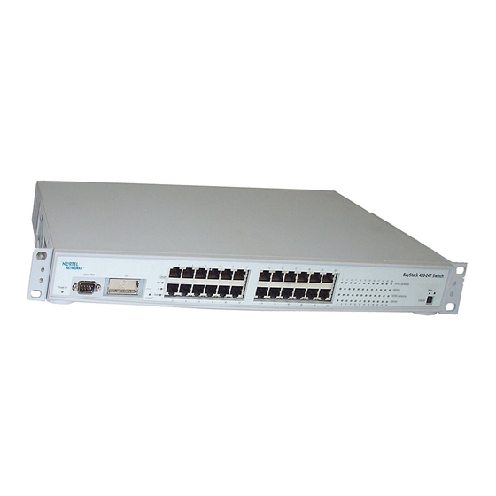
Chapter 1 BayStack 420 Switch This chapter introduces the BayStack 420 Switch and covers the following topics: • “Physical • “Features” on page 34 Physical description Figure 1 depicts the front and side views of the BayStack 420 Switch. Figure 1 BayStack 420 Switch description,”... -
Page 26: Front Panel
Chapter 1 BayStack 420 Switch Front panel Figure 2 shows the configuration of the front panel on the BayStack 420 Switch. Table 1 describes the components on the front panel. For descriptions of the back panel BayStack 420 Switch components, see panel”... -
Page 27: Gigabit Interface Converter (Gbic)
Gigabit Interface Converter (GBIC) Gigabit Interface Converters (GBICs) are hot-swappable input/output enhancement components designed for use with Nortel Networks products to allow Gigabit Ethernet ports to link with fiber optic networks. Port connectors The BayStack 420 Switch uses 10BASE-T/100BASE-TX RJ-45 (8-pin modular) port connectors. -
Page 28: Led Display Panel
Chapter 1 BayStack 420 Switch The 10BASE-T/100BASE-TX switch ports also support half- and full-duplex mode operation (refer to Installing the BayStack 420 10/100/1000 Switch). The 10BASE-T/100BASE-TX RJ-45 ports can connect to 10 Mb/s or 100 Mb/s Ethernet segments or nodes. -
Page 29: Table 2 Baystack 420 Switch Led Descriptions
The switch is connected to the downstream unit. The switch is configured as the stack base unit. The switch is not configured as the stack base unit (or is in standalone mode). Due to a stack error, the unit is unable to maintain the stack connection. -
Page 30: Back Panel
Two cooling fans are located on one side of the BayStack 420 Switch to provide cooling for the internal components. (See the switch, be sure to allow enough space on both sides of the switch for adequate air flow. See Installing the BayStack 420 10/100/1000 Switch for detailed information. -
Page 31: Ac Power Receptacle
Typical plug 220 or 230 VAC 50 Hz Single phase 100 or 120 VAC 50–60 Hz Single phase 240 VAC 50 Hz Single phase 240 VAC 50 Hz Single phase Using the BayStack 420 10/100/1000 Switch 228FA 227FA 229FA 230FA... - Page 32 Chapter 1 BayStack 420 Switch Caution: Please read immediately. Inspect this power cord and determine if it provides the proper plug and is appropriately certified for use with your electrical system. Immediately discard this cord if it is inappropriate for your country’s electrical system and obtain the proper cord as required by your national electrical codes or ordinances.
- Page 33 Advertencia: La única forma de desconectar la alimentación de este dispositivo es desenchufar el cable de alimentación. El cable de alimentación siempre debe estar conectado en una ubicación que permita acceder al cable de forma rápida y segura en caso de emergencia. Using the BayStack 420 10/100/1000 Switch...
-
Page 34: Features
Although Ethernet switches and bridges divide a network into smaller collision domains, they do not affect the broadcast domain. In simple terms, a virtual local area network provides a mechanism to fine-tune broadcast domains. Your BayStack 420 Switch allows you to create port-based VLANs: • IEEE 802.1Q port-based VLANs A port-based VLAN is a VLAN in which the ports are explicitly configured to be in the VLAN. -
Page 35: Security
Security The BayStack 420 Switch security features provide two levels of security for your local area network (LAN): • RADIUS-based security—limits administrative access to the switch through user authentication • MAC address-based security—limits access to the switch based on allowed... - Page 36 — MAC address-based security is used to allow up to 448 authorized stations (MAC addresses) access to one or more switch ports (see — The switch is located in a locked closet, accessible only by authorized Technical Services personnel. •...
-
Page 37: Radius-Based Network Security
Create a list of up to 448 MAC addresses and specify which addresses are authorized to connect to your switch or stack configuration. The 448 MAC addresses can be configured within a single standalone switch, or they can be distributed in any order among the units in a single stack configuration. -
Page 38: Flash Memory Storage
The response can be to send a trap, turn on destination address (DA) filtering, disable the specific port, or any combination of these three options. The MAC address-based security feature is based on Nortel Networks BaySecure LAN Access for Ethernet, a real-time security system that safeguards Ethernet networks from unauthorized surveillance and intrusion. -
Page 39: Multilink Trunking
You can specify port-based monitoring for ingress to a specific port. You can also attach a probe device (such as a Nortel Networks StackProbe, or equivalent) to the designated monitor port. -
Page 40: Rfcs
IEEE 802.3u autonegotiation standard. In this case, because it is not possible to sense the duplex mode of the attached device, the BayStack 420 Switch reverts to half-duplex mode. -
Page 41: Snmp Mib Support
SNMP MIB support The BayStack 420 Switch supports an SNMP agent with industry standard MIBs, as well as private MIB extensions, which ensures compatibility with existing network management tools. The switch supports the MIB-II (RFC 1213), Bridge MIB (RFC 1493), and the RMON MIB (RFC 1757), which provide access to detailed management statistics. -
Page 42: Snmp Trap Support
BootP automatic IP configuration/MAC address The BayStack 420 Switch has a unique 48-bit hardware address, or MAC address, that is printed on a label on the back panel. You use this MAC address when you configure the network BootP server to recognize the BayStack 420 Switch BootP requests. -
Page 43: Configuration And Switch Management
The BayStack 420 Switch is shipped directly from the factory ready to operate in any 10BASE-T or 100BASE-TX standard network. You must assign an IP address to the switch or stack, depending on the mode of operation. You can set both addresses by using the console port or BootP, which resides on the switch. - Page 44 Chapter 1 BayStack 420 Switch Optivity network management software consists of views, most of which are maps that illustrate the interconnections between the segments, rings, and nodes of your network. The views allow you to analyze network performance and fault conditions on the individual segments and specific areas in your network.
-
Page 45: Network Configuration
Use BayStack 420 switches to connect workstations, personal computers (PCs), and servers to each other by connecting these devices directly to the switch, through a shared media hub connected to the switch or by creating a virtual LAN (VLAN) through the switch. -
Page 46: Segment Switch Application
Segment switch application Figure 7 shows a BayStack 420 Switch used as a segment switch to alleviate user contention for bandwidth and eliminate server and network bottlenecks. Before segmentation, 88 users had a total bandwidth of only 10 Mb/s available. After segmentation, 92 users have 40 Mb/s, four times the previous bandwidth, while adding 22 dedicated 100 Mb/s connections. -
Page 47: Figure 7 Baystack 420 Switch Used As A Segment Switch
Figure 7 BayStack 420 Switch used as a segment switch Before 10BASE-T hubs Server Network Center 10 Mb/s 100 Mb/s 1000 Mb/s - 88 users share 10 Mb/s (10/88 Mb/s per user) - Server bottleneck (10 Mb/s bandwidth) - Network center bottleneck (10 Mb/s bandwidth) -
Page 48: High-Density Switched Workgroup Application
Figure 8 shows an example of using a BayStack 420 Switch with a high-speed (gigabit) connection to a Nortel Networks Passport* 1100 switch. BayStack 303 and BayStack 304 switches are also shown in this example of a high-density switched workgroup. -
Page 49: Baystack 420 Switch Stack Operation
(see displayed on the BayStack 420 Switch LED display panel. When the Unit Select switch is in the Base (in) position, all other Unit Select switches in the stack configuration must be set to Off (out). Chapter 2 Network configuration... -
Page 50: Base Unit
The base unit is the unique stack unit that you configure with the Unit Select switch on the front panel. One BayStack 420 Switch in the stack must be configured as the base unit; all other units in the stack must have their Unit Select switch set to Off (see BayStack 420 Switch as the base unit. -
Page 51: Removing A Unit From The Stack
9, data flows from the base unit (unit 1) to the next switch, which is assigned as unit 2, and continues until the last switch in the stack is assigned as unit 8. The physical order of the switches is from bottom to top (unit 1 to unit 8). -
Page 52: Stack Down Configurations
10, data flows from the base unit (unit 1) to the next switch, which is assigned as unit 2, and continues until the last switch in the stack is assigned as unit 8. The physical order of the switches is from top to bottom (unit 1 to unit 8). -
Page 53: Figure 10 Stack Down Configuration Example
Certain network management station (NMS) applications assume a stack down configuration for the graphical user interface (GUI) that represents the stack (see Figure 10). For this reason, Nortel Networks recommends that you always configure the top unit in the stack as the base unit. Chapter 2 Network configuration... -
Page 54: Ieee 802.1Q Vlan Workgroups
(Figure segment that is a single broadcast domain. When a switch port is configured to be a member of a VLAN, it is added to a group of ports (workgroup) that belong to one broadcast domain. -
Page 55: Ieee 802.1Q Tagging
Tagged frame— the 32-bit field (VLAN tag) in the frame header that identifies the frame as belonging to a specific VLAN. Untagged frames are marked (tagged) with this classification as they leave the switch through a port that is configured as a tagged port. - Page 56 • Untagged member—a port that has been configured as an untagged member of a specific VLAN. When an untagged frame exits the switch through an untagged member port, the frame header remains unchanged. When a tagged frame exits the switch through an untagged member port, the tag is stripped and the tagged frame is changed to an untagged frame.
-
Page 57: Figure 12 Default Vlan Settings
By default: All ports are assigned PVID = 1 All ports are untagged members of VLAN 1 When you configure VLANs, you configure the switch ports as tagged or untagged members of specific VLANs (see Figure 12, untagged incoming packets are assigned directly to VLAN 2 (PVID = 2). -
Page 58: Figure 13 Port-Based Vlan Assignment
Before As shown in switch through port 5, which is configured as a tagged member of VLAN 2. The untagged packet remains unchanged as it leaves the switch through port 7, which is configured as an untagged member of VLAN 2. -
Page 59: Figure 15 802.1Q Tag Assignment
Before As shown in switch through port 5, which is configured as a tagged member of VLAN 2. However, the tagged packet is stripped (untagged) as it leaves the switch through port 7, which is configured as an untagged member of VLAN 2. -
Page 60: Vlans Spanning Multiple Switches
Chapter 2 Network configuration VLANs spanning multiple switches You can use VLANs to segment a network within a switch. When you connect multiple switches, it is possible to connect users of one VLAN with users of that same VLAN in another switch. However, the configuration guidelines depend on whether both switches support 802.1Q tagging. -
Page 61: Vlans Spanning Multiple Untagged Switches
Figure 18 shows VLANs spanning multiple untagged switches. In this configuration, Switch S2 does not support 802.1Q tagging and you must use a single switch port on each switch for each VLAN. For this configuration to work properly, you must set spanning tree participation to Disabled (the STP is not supported across multiple LANs). -
Page 62: Figure 19 Possible Problems With Vlans And Spanning Tree Protocol
Because the other link connecting VLAN 2 is in Blocking mode, stations on VLAN 2 in Switch S1 cannot communicate with stations in VLAN 2 on Switch S2. With multiple links only one link will be forwarding. -
Page 63: Shared Servers
VLAN 1 (PVID=1) VLAN 2 (PVID=2) VLAN 3 (PVID=3) In the above configuration, all of the switch ports are set to participate as VLAN port members. This arrangement allows the switch to establish the appropriate broadcast domains within the switch... -
Page 64: Figure 21 Vlan Broadcast Domains Within The Switch
Chapter 2 Network configuration Figure 21 VLAN broadcast domains within the switch Port 2 PVID = 2 VLAN 1 (PVID = 1) VLAN 2 (PVID = 2) VLAN 3 (PVID = 3) For example, to create a broadcast domain for each VLAN shown in... -
Page 65: Figure 22 Default Vlan Configuration Screen Example
The default VLAN Configuration screen opens Figure 22 Default VLAN Configuration screen example The VLAN Configuration screen settings shown in with all switch ports classified as untagged members of VLAN 1. Figure 23 shows the VLAN Configuration screen after it is configured to support the VLAN 3 broadcast domain shown in optional). -
Page 66: Figure 23 Vlan Configuration Screen Example
Chapter 2 Network configuration Ports 2, 4, 6, 8, 10, and 11 are now untagged members of VLAN 3 as shown in Figure 21 Figure 23 VLAN Configuration screen example To configure the PVID (port VLAN identifier) for port 8: From the VLAN Configuration screen, press [Ctrl]-R to return to the VLAN Configuration Menu. -
Page 67: Figure 24 Default Vlan Port Configuration Screen Example
VLAN Port Configuration screen after it is configured to support the PVID assignment for port 8, as shown in Figure 21 on page 64 (Port Name is optional). The PVID/VLAN association for VLAN 3 is now PVID = 3. Using the BayStack 420 10/100/1000 Switch... -
Page 68: Vlan Workgroup Summary
Ports 2, 3, 4, 7, and 10 are in VLAN 2. • Port 8 is in VLAN 3. Because S4 does not support 802.1Q tagging, a single switch port on each switch must be used for each VLAN (see switches” on page The connection to S2 requires only one link between the switches because S1 and S2 are both BayStack 420 switches that support 802.1Q tagging (see... -
Page 69: Figure 26 Vlan Configuration Spanning Multiple Switches
Untagged ports (STP disabled) BayStack VLAN 1 (PVID=1) VLAN 2 (PVID=2) VLAN 3 (PVID=3) Chapter 2 Network configuration BayStack Both ports are tagged members of VLAN 1 and VLAN 2 Non-802.1Q tagging switch Using the BayStack 420 10/100/1000 Switch 10008EA... -
Page 70: Vlan Configuration Rules
MultiLink Trunks MultiLink Trunks allow you to group from two to four switch ports together to form a link to another switch or server, thus increasing aggregate throughput of the interconnection between the devices (up to 800 Mb/s in full-duplex mode). -
Page 71: Figure 27 Switch-To-Switch Trunk Configuration Example
Figure 28 shows a typical switch-to-server trunk configuration. In this example, file server FS1 uses dual MAC addresses, using one MAC address for each network interface card (NIC). For this reason, FS1 does not require a trunk assignment. -
Page 72: Client/Server Configuration Using Multilink Trunks
Clients accessing data from the servers (FS1 and FS2) are provided with maximized bandwidth through trunks T1, T2, T3, T4, and T5. Trunk members (the ports making up each trunk) do not have to be consecutive switch ports; you can select ports randomly, as shown by T5. -
Page 73: Trunk Configuration Screen Examples
Trunk Configuration screen” on page 135 Chapter 2 Network configuration BayStack 420 examples” following this section. For detailed information “MultiLink Trunk Configuration screen” on for more information. Using the BayStack 420 10/100/1000 Switch BayStack BayStack 420 10011EA “Trunk Figure 29. The screens show how 82, and “MultiLink... -
Page 74: Trunk Configuration Screen For Switch S1
Chapter 2 Network configuration Trunk configuration screen for Switch S1 Switch S1 is set up with five trunk configurations: T1, T2, T3, T4, and T5. To set up the S1 trunk configuration: Choose MultiLink Trunk Configuration (or press t) from the MultiLink... -
Page 75: Figure 31 Multilink Trunk Configuration Screen For Switch S1
Figure 31 MultiLink Trunk Configuration screen for Switch S1 Switch S1 is configured as follows: • Trunk (read only) indicates the trunks (1 to 6) that correspond to the switch ports specified in the Trunk Members fields. • Trunk Members (Unit/Port) indicates the ports that can be configured, in... -
Page 76: Trunk Configuration Screen For Switch S2
The names chosen for this example provide meaningful information to the user of this switch (for example, S1:T1 to FS2 indicates that Trunk 1, in Switch S1, connects to File Server 2). Trunk configuration screen for Switch S2 As shown in configurations (T2 and T3). -
Page 77: Figure 32 Multilink Trunk Configuration Screen For Switch S2
Figure 32 MultiLink Trunk Configuration screen for Switch S2 Switch S2 is configured as follows: • Trunk (read only) indicates the trunks (1 to 6) that correspond to the switch ports specified in the Trunk Members fields. • Trunk Members (Unit/Port) indicates the ports that can be configured, in each row, to create the corresponding trunk: —... -
Page 78: Trunk Configuration Screen For Switch S3
The names chosen for this example provide meaningful information to the user of this switch (for example, S2:T2 to S1 indicates that Trunk 1, in Switch S2, connects to Switch 1). Trunk Configuration screen for Switch S3 As shown in configuration (T4). -
Page 79: Trunk Configuration Screen For Switch S4
Switch S3 is configured as follows: • Trunk (read only) indicates the trunk (1 to 6) that corresponds to the switch ports specified in the Trunk Members fields. • Trunk Members (Unit/Port) indicates the ports that can be configured, in each row, to create the corresponding trunk. -
Page 80: Figure 34 Multilink Trunk Configuration Screen For Switch S4
Figure 34 MultiLink Trunk Configuration screen for Switch S4 Switch S4 is configured as follows: • Trunk (read only) indicates the trunk (1 to 6) that corresponds to the switch ports specified in the Trunk Members fields. • Trunk Members (Unit/Port) indicates the ports that can be configured, in each row, to create the corresponding trunk. -
Page 81: Before You Configure Trunks
The names chosen for this example provide meaningful information to the user (for example, S4:T5 to S1 indicates that Trunk 1, in Switch S4, connects to Switch 1). Before you configure trunks When you create and enable a trunk, the trunk members (switch ports) take on certain settings necessary for correct operation of the MultiLink Trunking feature. -
Page 82: Spanning Tree Considerations For Multilink Trunks
10 Mb/s 10 Mb/s Aggregate Bandwidth 220 Mb/s 209418-A Figure 35 shows a four-port trunk (T1) with BayStack BayStack 420-24T Switch 100 Mb/s 100 Mb/s Path Cost T2 = 4 10 Mb/s Aggregate Bandwidth 210 Mb/s BayStack BayStack 420-24T Switch... -
Page 83: Figure 36 Example 1: Correctly Configured Trunk
Figure 36, trunk member ports 2, 4, and 6 of Switch S1 are configured correctly to trunk member ports 7, 9, and 11 of Switch S2. The Spanning Tree Port Configuration screen for each switch shows the port state field for each port in the Forwarding state. -
Page 84: Figure 37 Example 2: Detecting A Misconfigured Port
Chapter 2 Network configuration If Switch S2’s trunk member port 11 is physically disconnected and then reconnected to port 13, the Spanning Tree Port Configuration screen for Switch S1 changes to show port 6 in the Blocking state Figure 37 Example 2: detecting a misconfigured port... -
Page 85: Additional Tips About The Multilink Trunking Feature
You can designate one of your switch ports to monitor ingress traffic on a single specified switch port (port-based). Note: A probe device, such as Nortel Networks StackProbe, must be connected to the designated monitor port to use this feature (contact your Nortel Networks sales agent for details about the StackProbe). -
Page 86: Figure 38 Port Mirroring Configuration Port-Based Screen Example
For example, when you configure a switch for port mirroring or when you modify an existing port mirroring configuration, the new configuration does not take effect until you respond [Yes] to the following screen prompt:... -
Page 87: Using The Console Interface
BayStack 420 Switch, remotely through a dial-up modem connection, or in-band through a Telnet session (see You can connect your console cable into any unit in a BayStack 420 Switch-only stack for a unified stack interface. For the mixed stack management functions to become fully operational, you must connect your console terminal into a BayStack 420 Switch port within your mixed stack. -
Page 88: Using The Ci Menus And Screens
The option takes effect immediately after you press [Enter]. Alternatively, you can press the key corresponding to the underlined letter in the option name. For example, to select the Switch Configuration option in the main menu, press the w key. Note that the text characters are not case-sensitive. -
Page 89: Screen Fields And Descriptions
Reset Reset to Default Settings Logout Only appears when the switch is participating in a stack configuration. Only appears when a gigabit MDA is installed in one or more units in a stack configuration. Chapter 3 Using the console interface... -
Page 90: Main Menu
Chapter 3 Using the console interface The CI screens for your specific switch model will show the correct model name in the main menu screen title and the correct number of ports and port types in the Port Configuration screen. -
Page 91: Figure 40 Console Interface Main Menu
MAC address. This screen also contains three user-configurable fields: sysContact, sysName, and sysLocation. When the switch is part of a stack configuration, this screen also displays the base unit identification, the number of units configured in the stack, and the local unit stack number. - Page 92 If the switch is participating in a stack configuration, you can reset the entire stack. • When you select this option, the switch resets, runs a self-test, then displays the Nortel Networks logo screen. Press [Ctrl]-Y to access the BayStack 420 Switch main menu. 209418-A 103). This menu provides the following configuration 147).
- Page 93 • When you select this option, the switch resets, runs a self-test, then displays the Nortel Networks logo screen. Press [Ctrl]-Y to access the BayStack 420 Switch main menu. Logout Allows a user in a Telnet session or a user working at a password-protected console terminal to terminate the session.
-
Page 94: Ip Configuration/Setup Screen
Chapter 3 Using the console interface IP Configuration/Setup screen The IP Configuration/Setup screen BayStack 420 Switch IP configuration parameters. Data that you enter in the user-configurable fields takes effect as soon as you press [Enter]. To open the IP Configuration/Setup screen: Choose IP Configuration/Setup (or press i) from the main menu. -
Page 95: Table 10 Ip Configuration/Setup Screen Fields
Default Value Range In-Band Switch The in-band IP address of the switch. This field is not required for the operation of the IP Address stack. This field can not use the same IP address used for the stack. Default Value... -
Page 96: Choosing A Bootp Request Mode
The subnet address mask associated with the in-band IP address shown on the screen Mask (see In-Band Switch IP address field). Network routers use the subnet mask to determine the network or subnet address portion of a host’s IP address. The bits in the IP address that contain the network address (including the subnet) are set to 1 in the address mask, and the bits that contain the host identifier are set to 0. -
Page 97: Bootp When Needed
BootP When Needed Allows the switch to request an IP address if one has not already been set from the console terminal. When selected, this mode operates as follows: • When the IP data is entered from the console terminal, the data becomes the in-use address of the switch and BootP requests are not broadcast. -
Page 98: Bootp Disabled
The switch can be managed only by using the in-band switch IP address set from the console terminal. These actions take effect after the switch is reset or power cycled, even if an IP address is not currently in use. -
Page 99: Snmp Configuration Screen
Chapter 3 Using the console interface (Figure 42) allows you to set or modify the Description The community string used for in-band read-only SNMP operations. Default Value public Range Any ASCII string of up to 32 printable characters Using the BayStack 420 10/100/1000 Switch... -
Page 100: System Characteristics Screen
Autotopology 1 The Trap IP Address and Community String fields can be set using a MIB table (in a Nortel Networks proprietary MIB). The status of the row in the MIB table can be set to Ignore. If the row status is set to Ignore, the fields appear to be set when viewed from the console terminal;... -
Page 101: Figure 43 System Characteristics Screen
Read-only field that indicates the operation mode of the unit, for example: • When the unit is part of a stack configuration, the (read-only) field indicates the unit is operational in a stack, and lists the current unit number of this switch. In this example (see •... - Page 102 A read-only field that specifies hardware and software versions. sysObjectID A read-only field that provides a unique identification of the switch, which contains the vendor’s private enterprise number. sysUpTime A read-only field that shows the length of time since the last reset. Note that this field is updated when the screen is redisplayed.
-
Page 103: Switch Configuration Menu Screen
The Switch Configuration Menu screen (Figure 44) allows you to set or modify your switch configuration. Choose Switch Configuration (or press w) from the main menu to open the Switch Configuration Menu screen (Table 13). Figure 44 Switch Configuration Menu screen... -
Page 104: Table 13 Switch Configuration Menu Options
105). This screen allows you to view all MAC addresses and their associated port or trunk that the switch has learned, or to search for a particular MAC address (to see if the switch has learned the address). Displays the MAC Address Security Configuration menu (see Address Security Configuration Menu screen”... -
Page 105: Mac Address Table Screen
MAC Address Table screen The MAC Address Table screen that the switch has discovered or to search for a specific MAC address. The MAC Address Table screen also operates in conjunction with the Port Mirroring Configuration screen. When you configure a switch for MAC address-based port mirroring, you can use the MAC Address Table screen to find an address and enter the address directly from this screen. -
Page 106: Figure 45 Mac Address Table Screen
Table 14 MAC Address Table screen fields Field Description Aging Time Specifies how long a learned MAC address remains in the switch’s forwarding database. If an entry is inactive for a period of time that exceeds the specified aging time, the address is removed. Default Value... -
Page 107: Mac Address Security Configuration Menu Screen
The MAC Address Security Configuration Menu screen specify a range of system responses to unauthorized network access to your switch. The system response can range from sending a trap to disabling the port. The network access control is based on the MAC addresses of the authorized stations. -
Page 108: Table 15 Mac Address Security Configuration Menu Options
The MAC Address Security Configuration screen enable or disable the MAC address security feature and to specify the appropriate system responses to any unauthorized network access to your switch. Choose MAC Address Security Configuration from the MAC Address Security Configuration Menu to open the MAC Address Security Configuration screen. -
Page 109: Figure 47 Mac Address Security Configuration Screen
MAC Address Security When this field is set to enabled, the MAC address security screens cannot SNMP-Locked be modified using SNMP. Default Range Chapter 3 Using the console interface Disabled Disabled, Enabled Disabled Disabled, Enabled Using the BayStack 420 10/100/1000 Switch... - Page 110 Field Description Partition Port on Intrusion This field value determines how the switch reacts to an intrusion event. When Detected: an intrusion even is detected (see MAC Address Security field description) the specified switch port is set to Disabled (partitioned from other switch ports).
-
Page 111: Mac Address Security Port Configuration Screen
Range Current Learning Mode Indicates the current learning mode for the switch ports. When this field is set to Learning in Progress, all source MAC addresses of any packets received on the specified port (or ports) are added to the MAC Security Table (maximum of 448 MAC address entries allowed). -
Page 112: Figure 48 Mac Security Port Configuration Screen (1 Of 2)
Chapter 3 Using the console interface Figure 48 MAC Security Port Configuration screen (1 of 2) Figure 49 MAC Security Port Configuration screen (2 of 2) 209418-A... -
Page 113: Mac Address Security Port Lists Screens
Displays the trunk number if the port is a member of that trunk. Default Security This field value determines whether or not security is enabled or disabled on the port level or switch level. Default Range MAC Address Security Port Lists screens... -
Page 114: Figure 50 Mac Address Security Port Lists Screens
Chapter 3 Using the console interface Figure 50 MAC Address Security Port Lists screens MAC Address Security Port Lists Entry Port List ----- --------- MAC Address Security Port Lists Entry Port List ----- --------- MAC Address Security Port Lists Entry Port List ----- ---------... -
Page 115: Port List Syntax
When you enter a port list in a stack configuration, you must specify either a unit/ port list, NONE, or ALL. In a stack configuration, ALL indicates all of the stack port; whereas, in a standalone scenario, ALL indicates all of the switch ports. Note: NONE and ALL must be entered in uppercase characters as shown in the screen prompt. -
Page 116: Accelerator Keys For Repetitive Tasks
Chapter 3 Using the console interface A unit/port number list is composed of one or more list items, each of which can be a single number or a range of numbers (where the numbers represents one or more ports). If a list item is preceded by a number and then a slash (/), the number represents a stack unit. - Page 117 Highlight the (blank) Allowed Source field. Enter the period (.) character and click Return. The port number list from the previous entry is copied into the new field. Chapter 3 Using the console interface Using the BayStack 420 10/100/1000 Switch...
-
Page 118: Mac Address Security Table Screens
Chapter 3 Using the console interface MAC Address Security Table screens The MAC Address Security Table screens allow you specify the ports that each MAC address is allowed to access. You must also include the MAC addresses of any routers that are connected to any secure ports. There are 16 available MAC Address Security Table screens can use to create up to 448 MAC address entries (28 per screen). -
Page 119: Table 19 Mac Address Security Table Screen Fields
MAC Address Allows you to specify up to 448 MAC addresses that are authorized to access the switch. You can specify the ports that each MAC address is allowed to access using the Allowed Source field (see next field description). The... -
Page 120: Vlan Configuration Menu Screen
Chapter 3 Using the console interface Table 19 MAC Address Security Table screen fields (continued) Field Description Default Range 1 Multicast address -- Note that the first octet of any Multicast address will always be an odd number. VLAN Configuration Menu screen The VLAN Configuration Menu screen appropriate screen to configure up to 32 VLANs. -
Page 121: Figure 54 Vlan Configuration Menu Screen
Configuration Menu screen. Chapter 3 Using the console interface 122). This screen allows you to set up VLAN workgroups. 125). This screen allows you to set up a specific switch port. 127). Using the BayStack 420 10/100/1000 Switch “VLAN Configuration screen” on “VLAN Port Configuration... -
Page 122: Vlan Configuration Screen
When you configure ports as VLAN port members, they become part of a set of ports that form a broadcast domain for a specific VLAN. You can assign switch ports, whether standalone or stacked unit ports, as VLAN port members of one or more VLANs. -
Page 123: Figure 55 Vlan Configuration Screen
If you delete a VLAN, all configuration parameters that are associated with that VLAN are deleted also. You cannot delete VLAN 1. By default, all switch ports are assigned as untagged members of VLAN 1 with all ports configured as PVID = 1. See workgroups”... - Page 124 Allows you to assign a name field to configured VLANs. Default Range Management VLAN Allows you to assign any VLAN as the management VLAN. VLAN 1 is the default management VLAN for the switch. To set this field, the VLAN State field value must be Active. Default Range...
-
Page 125: Vlan Port Configuration Screen
(T) or as a non-VLAN port member (-). The Port Membership fields are displayed in six-port groups (for example, 1-6, 7-12, 13-18). The number of ports displayed depends on the switch model or type of optional GBIC installed in the Uplink Module slot. Default... -
Page 126: Figure 56 Vlan Port Configuration Screen
Port Name 209418-A Description Allows you to select a switch in your stack. To view another switch, type its switch number and press [Enter], or press the spacebar to toggle the switch numbers. Allows you to select the number of the port you want to view or configure. -
Page 127: Vlan Display By Port Screen
VLAN Display by Port screen The VLAN Display by Port screen characteristics associated with a specified switch port. Choose VLAN Display by Port (or press d) from the VLAN Configuration Menu screen to open the VLAN Display by Port screen. -
Page 128: Figure 57 Vlan Display By Port Screen
Field Description Unit Allows you to select a switch in your stack. To view another switch, type its switch number and press [Enter], or press the spacebar to toggle the switch numbers. Port Allows you to select the number of the port you want to view. To view another port, type its port number and press [Enter], or press the spacebar on your keyboard to toggle the port numbers. -
Page 129: Port Configuration Screen
Port Configuration screen The Port Configuration screen (Figures specific switch ports or all switch ports. You can enable or disable the port status of specified switch ports, set the switch ports to autonegotiate for the highest available speed of the connected station, or set the speed for selected switch ports (autonegotiation is not supported on fiber optic ports). -
Page 130: Figure 59 Port Configuration Screen (2 Of 2)
(for example, the field values in row 2 apply to switch port 2). The values that you set in the Switch row will affect all switch ports and, when the switch is part of a stack, the values that you set in the Stack row will affect all ports in the entire stack (except the GBIC ports or fiber optic ports). -
Page 131: High Speed Flow Control Configuration Screen
Gigabit Ethernet Interface. Note: The GBIC module does not need to be installed to configure the port. Choose High Speed Flow Control Configuration (or press h) from the Switch Configuration Menu screen to open the High Speed Flow Control Configuration screen. -
Page 132: Figure 60 High Speed Flow Control Configuration
Chapter 3 Using the console interface Figure 60 High Speed Flow Control Configuration Table 25 describes the High Speed Flow Control Configuration screen fields. Table 25 High Speed Flow Control Configuration screen fields Field Description Unit Allows you to select the unit number (when stacking is configured) to view or configure. -
Page 133: Choosing A High Speed Flow Control Mode
Gigabit full-duplex link. If the receive port buffer becomes full, the BayStack 420 Switch issues a flow-control signal to the device at the other end of the link to suspend transmission. When the receive buffer is no longer full, the switch issues a signal to resume the transmission. -
Page 134: Figure 61 Multilink Trunk Configuration Menu Screen
Trunk Status field to Enabled. To open the MultiLink Trunk Configuration Menu screen: Choose MultiLink Trunk Configuration (or press t) from the Switch Configuration Menu screen. Figure 61 MultiLink Trunk Configuration Menu screen 209418-A “MultiLink... -
Page 135: Multilink Trunk Configuration Screen
MultiLink Trunk Displays the MultiLink Trunk Configuration screen Configuration... allows you to configure up to six MultiLink Trunks within a standalone switch or within a stack configuration. You can group up to four switch ports together to form each trunk. -
Page 136: Figure 62 Multilink Trunk Configuration Screen
The Unit value in the (Unit/Port) field is configurable only when the switch (unit) is part of a stack configuration. It indicates that the trunk members in this row are associated with the specified unit number configured in the Unit field. Each switch port can only be a member of a single trunk. -
Page 137: Multilink Trunk Utilization Screen
The Trunk Mode column contains a single read only field for each row that indicates the default operating mode for the switch. Basic: Basic mode is the default mode for the switch. When in this mode, source MAC addresses are dynamically assigned to specific trunk members for flooding and forwarding, which allows the switch to stabilize and distribute the data streams of source addresses across the trunk members. -
Page 138: Figure 63 Multilink Trunk Utilization Screen (1 Of 2)
Chapter 3 Using the console interface Figure 63 MultiLink Trunk Utilization screen (1 of 2) Figure 64 MultiLink Trunk Utilization screen (2 of 2) 209418-A... -
Page 139: Port Mirroring Configuration Screen
Description Trunk Column header for the read-only fields in this screen. The read-only data displayed in this column indicates the trunk (1 to 6) that corresponds to the switch ports specified in the Port field. Traffic Type Allows you to choose the traffic type to be monitored for percent of bandwidth utilization (see Range). -
Page 140: Figure 65 Port Mirroring Configuration Screen
Chapter 3 Using the console interface To open the Port Mirroring Configuration screen: Choose Port Mirroring Configuration (or press i) from the Switch Configuration Menu screen. Figure 65 Port Mirroring Configuration screen Table 29 describes the Port Mirroring Configuration screen fields. -
Page 141: Port Statistics Screen
Port Statistics screen The Port Statistics screen about any switch or port in a stacked or standalone configuration. The screen is divided into two sections (Received and Transmitted) so that you can compare and evaluate throughput or other port parameters. All screen data is updated approximately every 2 seconds. -
Page 142: Figure 66 Port Statistics Screen
Chapter 3 Using the console interface To open the Port Statistics screen: Choose Display Port Statistics (or press d) from the Switch Configuration Menu screen. Figure 66 Port Statistics screen Table 31 describes the Port Statistics screen fields. Note: In a stacked configuration, the Port Statistics screen appears in a slightly different format when the port selected in the Unit/Port field is configured with a GBIC. -
Page 143: Table 31 Port Statistics Screen Fields
Description Unit Only appears if the switch is participating in a stack configuration. The field allows you to select the number of the unit you want to view or configure. To view or configure another unit, type its unit number and press [Enter], or press the spacebar on your keyboard to toggle the unit numbers. - Page 144 Chapter 3 Using the console interface Table 31 Port Statistics screen fields (continued) Field Description 128-255 bytes Received column: Indicates the total number of 128-byte to 255-byte packets received on this port. Transmitted column: Indicates the total number of 128-byte to 255-byte packets transmitted successfully on this port.
-
Page 145: System Log Screen
(NVRAM) or dynamic random access memory (DRAM) and NVRAM. When the switch is part of a stack configuration, the System screen displays only the data for the BayStack 420 Switch you are connected to through the Console/Comm port. -
Page 146: Figure 67 System Log Screen
This field only appears if the switch is participating in a stack configuration. The field allows you to select the unit number of the BayStack 420 Switch you want to view. To view the log messages of another BayStack 420 Switch, type its unit number and press [Enter], or press the spacebar on your keyboard to toggle the unit numbers. -
Page 147: Console/Comm Port Configuration Screen
The Console/Comm Port Configuration screen configure and modify the console/comm port parameters and security features of a standalone switch or any participating switch in a stack configuration. To open the Console/Comm Port Configuration screen: Choose Console/Comm Port Configuration (or press o) from the main menu. -
Page 148: Figure 68 Console/Comm Port Configuration Screen
Chapter 3 Using the console interface Figure 68 Console/Comm Port Configuration screen Table 33 describes the Console/Comm Port Configuration screen fields. Table 33 Console/Comm Port Configuration screen fields Field Description Comm Port Data Bits A read-only field that indicates the current console/comm port data bit setting. Comm Port Parity A read-only field that indicates the current console/comm port parity setting. - Page 149 If you set this field to Required, you can use the Logout option to restrict access to the CI. Thereafter, you will need to specify the correct password at the console-terminal prompt. See Console Read-Only Switch Password and Console Read-Write Switch Password for more information.
- Page 150 Switch Password Console, or for Both), this field allows read-write password access to the CI of a standalone switch. Users can log in to the CI using the correct password (see default) and can change any parameter, except the stack passwords.
- Page 151 Si olvida las nuevas contraseñas, no podrá acceder al interfaz de la consola. En ese caso, póngase en contacto con Nortel Networks para obtener ayuda al respecto. Attenzione: In caso di modifica delle password predefinite nel sistema, assicurarsi di annotare le nuove password e di conservarle in un luogo sicuro.
- Page 152 Console, or for Both), this field allows read-write password access to the CI of any participating switch in a stack configuration. Users can log in to the CI using the correct password (see default), and can change any parameter, except the switch password.
- Page 153 Nel caso in cui le nuove password vengano dimenticate, non sarà possibile accedere all'interfaccia della console. In tal caso, contattare la Nortel Networks per avere assistenza. 0.0.0.0 (no IP address assigned) Four-octet dotted-decimal notation, where each octet is represented as a decimal value, separated by a decimal point 0.0.0.0 (no IP address assigned)
-
Page 154: Renumber Stack Units Screen
Mb/s port) LEDs on each unit for approximately 10 seconds. For example, unit 3 will display three LEDs. Note: This menu option and screen appears only when the switch is participating in a stack configuration. To open the Renumber Stack Units screen: Choose Renumber Stack Units (or press n) from the main menu. -
Page 155: Hardware Unit Information Screen
Yes. Renumbering resets the switch with the current configuration values. When you select this option, the switch resets, runs a self-test, then displays the Nortel Networks logo screen. After you press [Ctrl]-Y at the screen prompt, the console screen temporarily displays the (standalone) BayStack 420 Switch main menu. -
Page 156: Spanning Tree Configuration Menu Screen
Figure 70 Hardware Unit Information screen Spanning Tree Configuration Menu screen The Spanning Tree Configuration Menu screen spanning tree parameters and configure individual switch ports to participate in the spanning tree algorithm (STA). To modify any of the spanning tree parameters, see your SNMP documentation. -
Page 157: Figure 71 Spanning Tree Configuration Menu Screen
Description Displays the Spanning Tree Port Configuration screen (see “Spanning Tree Port Configuration screen” on page Displays the Spanning Tree Switch Settings screen (see “Spanning Tree Switch Settings screen” on page Exits the Spanning Tree Configuration Menu and displays the main menu. -
Page 158: Spanning Tree Port Configuration Screen
Spanning Tree Port Configuration screen The Spanning Tree Port Configuration screen allows you to configure individual switch ports or all switch ports for participation in the spanning tree. Note: If spanning tree participation of any trunk member is changed (enabled or disabled), the spanning tree participation of all members of that trunk is changed similarly. -
Page 159: Figure 73 Spanning Tree Port Configuration Screen (2 Of 2)
(for example, the field values in row 2 apply to switch port 2). Note that the values in the Switch row affect all switch ports and, when the switch is part of a stack, the values in the Stack row affect all ports in the entire stack. - Page 160 Description Participation Allows you to configure any (or all) of the switch ports for Spanning tree participation. When an individual port is a trunk member (see Trunk field), changing this setting for one of the trunk members changes the setting for all members of that trunk. You should consider how this can change your network topology before you change this setting.
-
Page 161: Spanning Tree Switch Settings Screen
BayStack 420 Switch. To open the Spanning Tree Switch Settings screen: Choose Display Spanning Tree Switch Settings (or press d) from the Spanning Tree Configuration Menu screen. Figure 74 Spanning Tree Switch Settings screen... -
Page 162: Table 37 Spanning Tree Switch Settings Parameters
Indicates the bridge ID of the root bridge, as determined by the STA. Root Default Value Range Root Port Indicates the switch port number that offers the lowest path cost to the root bridge. Default Value Range Root Path Cost Indicates the path cost from this switch port to the root bridge. - Page 163 Table 37 Spanning Tree Switch Settings parameters (continued) Parameter Description Forward Delay Indicates the Forward Delay parameter value that the root bridge is currently using. This value specifies the amount of time that the bridge ports remain in the Listening and Learning states before entering the Forwarding state.
-
Page 164: Telnet Configuration Screen
Chapter 3 Using the console interface TELNET Configuration screen The TELNET Configuration screen terminal to communicate with the BayStack 420 Switch as if the console terminal were directly connected to it. You can have up to four active Telnet sessions at one time. -
Page 165: Table 38 Telnet Configuration Screen Fields
None: Indicates that no Telnet events will be logged in the Event Log screen. Accesses: Logs only Telnet connect and disconnect events in the Event Log screen. Failures: Logs only failed Telnet connection attempts in the Event Log screen. Using the BayStack 420 10/100/1000 Switch “System... -
Page 166: Software Download Screen
Software Download screen The Software Download screens BayStack 420 Switch software image that is located in nonvolatile flash memory. Caution: Do not interrupt power to the device during the software download process. If the power is interrupted, the firmware image can become corrupted. - Page 167 To download the software image, you need a properly configured Trivial File Transfer Protocol (TFTP) server in your network, and an IP address for the switch (or stack, if configured). To learn how to configure the switch or stack IP address, refer to “IP Configuration/Setup screen”...
-
Page 168: Figure 76 Software Download Screen For A Baystack 420 Switch Stack
Image Filename NOTE: Certain software releases may require you to download two images: the boot code image and the agent image. For proper operation of the switch, the new boot code image must be downloaded before the agent image is downloaded. -
Page 169: Led Indications During The Download Process
NOTE: The software download process can take up to 60 seconds to complete (or more if the load host path is congested or there is a high volume of network traffic). To ensure that the download process is not interrupted, do not power down the switch for approximately 10 minutes. -
Page 170: Figure 77 Configuration File Download/Upload Screen
Chapter 3 Using the console interface You can retrieve the configuration parameters of a standalone switch or an entire stack and use the retrieved parameters to automatically configure a replacement switch or stack. Certain requirements apply when automatically configuring a... -
Page 171: Table 40 Configuration File Download/Upload Screen Fields
The IP address of your TFTP load host. Default Value Range Copy Configuration Specifies whether to copy the presently configured switch/stack parameters to Image to Server the specified TFTP server (default is No). Use the spacebar to toggle the selection to Yes. -
Page 172: Requirements
• A configuration file obtained from a standalone switch can only be used to configure other standalone switches that have the same firmware revision and model type as the donor standalone switch. -
Page 173: Troubleshooting
“Diagnosing and correcting problems” on page 175 — Normal power-up sequence — Port connection problems The chapter topics lead you through a logical process for troubleshooting the BayStack 420 Switch. For example, because LEDs provide visual indications of certain problems, see various states operation. -
Page 174: Figure 78 Led Display Panel
The switch is connected to the downstream unit. The switch is configured as the stack base unit. The switch is not configured as the stack base unit (or is in standalone mode). Due to a stacking error the unit is unable to maintain the stack connection. -
Page 175: Diagnosing And Correcting Problems
Diagnosing and correcting problems Before you perform the problem-solving steps in this section, cycle the power to the BayStack 420 Switch (disconnect and then reconnect the AC power cord); then verify that the switch follows the normal power-up sequence. Warning: To avoid bodily injury from hazardous electrical current, never remove the top cover of the device. -
Page 176: Normal Power-Up Sequence
Normal power-up sequence In a normal power-up sequence, the LEDs appear as follows: After power is applied to the switch, the Pwr (Power) LED turns on within 5 seconds. The switch initiates a self-test, during which the port LEDs display various patterns to indicate the progress of the self-test. -
Page 177: Port Connection Problems
• If the autonegotiation feature is not present or not enabled at the connected station, the BayStack 420 Switch may not be able to determine the correct duplex modes. Chapter 4 Troubleshooting Corrective action “Port connection... -
Page 178: Port Interface
Chapter 4 Troubleshooting In both situations, the BayStack 420 Switch “autosenses” the speed of the connected station and, by default, reverts to half-duplex mode. If the connected station is operating in full-duplex mode, it cannot communicate with the switch. To correct this mode mismatch problem:... -
Page 179: Technical Specifications
BayStack 420 Switch. Table 44 Environmental specifications Parameter Temperature Humidity Altitude Electrical Table 45 lists power electrical parameters for the BayStack 420 Switch. Table 45 Electrical parameters Parameter Input Voltage Input Power Consumption Input Volt Amperes Rating Operating specification 0°... -
Page 180: Physical Dimensions
Appendix A Technical specifications Table 45 Electrical parameters (continued) Parameter Input current Maximum thermal output Physical dimensions Table 46 lists physical dimensions for the BayStack 420 Switch. Table 46 Physical dimensions Parameter Height Width Depth Weight Performance specifications Table 47 lists performance specifications for the BayStack 420 Switch. -
Page 181: Network Protocol And Standards Compatibility
Network protocol and standards compatibility The following are protocols and standards used by the BayStack 420 Switch: • IEEE 802.3 10BASE-T (ISO/IEC 8802-3, Clause 14) • IEEE 802.3u 100BASE-TX (ISO/IEC 8802-3, Clause 25) • IEEE 802.1Q (VLAN Tagging) • IEEE 802.1z (Gigabit) •... -
Page 182: Electromagnetic Immunity
Appendix A Technical specifications Electromagnetic immunity The BayStack 420 Switch meets the EN50082-1:1997 standard. 209418-A... -
Page 183: Installing A Gigabit Interface Converter (Gbic)
(GBIC). It also provides a description of the GBIC, the GBIC label, and GBIC specifications. Product description GBICs are hot-swappable input/output enhancement components designed for use with Nortel Networks products to allow Gigabit Ethernet ports to link with fiber optic networks. The following GBIC versions are available for the BayStack 420 Switch: •... -
Page 184: Gbic Labeling
Figure 80 Nortel label on a GBIC Part number Serial number Note: You must have the Nortel Networks serial number, the manufacturer’s code, the interface type, and the part number of your GBIC available when you contact a Nortel Networks service representative for troubleshooting purposes. -
Page 185: Gbic Models
GBIC Models Table 48 lists the available Nortel Networks GBIC models. Table 48 Nortel Networks GBIC models Model number 1000BASE-SX 1000BASE-LX 1000BASE-XD 1000BASE-ZX GBIC specifications GBIC specifications are listed in Table 49 GBIC specifications Specifications Dimensions (H x W x D) -
Page 186: 1000Base-Lx
Appendix B Installing a Gigabit Interface Converter (GBIC) Table 50 describes standards, connectors, cabling, and distance for the Model 1000BASE-SX GBIC. Table 50 Model 1000BASE-SX GBIC specifications Type Standards Connectors Cabling Distance Wavelength Optical budget Laser Transmitter Characteristics Minimum launch power Maximum launch power Receiver Characteristics Minimum receiver sensitivity... -
Page 187: Table 51 Model 1000Base-Lx Gbic Specifications
Note: When multimode fiber is used in long distance applications, external, removable, mode-conditioning patch cords may be required to prevent differential mode delay (DMD). You can order mode conditioning patch cords through Nortel Networks: • SC-SC Mode Conditioning Patch Cord 62.5/125—part number AA0018035 SC-SC Mode Conditioning Patch Cord 50/125—part number... -
Page 188: 1000Base-Xd
Wavelength Minimum receiver sensitivity Maximum input power Note: Nortel Networks recommends that you use an in-line attenuator for shorter link distances to avoid overloading the receiver. Note: The Model 1000BASE-XD GBIC is based on proprietary signaling and is compatible with Accelar 1000 Series XD modules. -
Page 189: 1000Base-Zx
22 dB 1550 ± 10 nm 0.2 nm 3.0 mW ± 5 dBm 0 dBm 70 km 1200 nm to 1550 nm -22 dBm -3 dBm Using the BayStack 420 10/100/1000 Switch... -
Page 190: Handling, Safety, And Environmental Guidelines
50 km. Note: The 1000BASE-ZX GBIC is based on proprietary signaling. Nortel Networks recommends that this product be used only with other Nortel Networks 1000BASE-ZX GBICs. Handling, safety, and environmental guidelines... -
Page 191: Installing A Gbic
GBIC bays are covered by spring-loaded filler panels that rotate out of the way as you push the GBIC into place. You can install or replace a GBIC in a BayStack 420 Switch without turning off power to the switch. Warning: Fiber optic equipment can emit laser or infrared light that can injure your eyes. -
Page 192: Figure 81 Installing A Gbic
To install a GBIC: Remove the GBIC from its protective packaging. Insert the GBIC into the slot on the BayStack switch GBICs are keyed to prevent improper insertion. If the GBIC resists pressure, do not force it. Remove it, turn it over, and reinsert it. -
Page 193: Quick Configuration For Multilink Trunking
Appendix C Quick configuration for MultiLink Trunking If you are a system administrator with experience configuring BayStack 420 Switch MultiLink Trunking, use the flowchart in configuration guide. The flowchart refers you to the “configuration rules” appropriate for this feature. To open the MultiLink Trunk Configuration screen: Choose MultiLink Trunk Configuration (or press t) from the MultiLink Trunk Configuration Menu screen. -
Page 194: Figure 83 Configuring Multilink Trunks
Appendix C Quick configuration for MultiLink Trunking Figure 83 Configuring MultiLink Trunks MultiLink Trunk Configuration screen Are all trunk members configured? Is trunk STP Enabled? Is trunk Enabled? Done 209418-A Configure trunk members (see "MultiLink Trunking Configuration Rules"). Configure STP field. Enable Trunk Status field (see "MultiLink Trunking Configuration Rules"). -
Page 195: Connectors And Pin Assignments
Appendix D Connectors and pin assignments This appendix describes the BayStack 420 Switch port connectors and pin assignments. RJ-45 (10BASE-T/100BASE-TX) port connectors The RJ-45 port connectors end stations without using crossover cables. (See page 196 for information about MDI-X ports.) For 10BASE-T connections, use Category 3 (or higher) UTP cable. -
Page 196: Mdi And Mdi-X Devices
Appendix D Connectors and pin assignments Table 54 lists the RJ-45 (8-pin modular) port connector pin assignments. Table 54 RJ-45 port connector pin assignments MDI and MDI-X devices Media dependent interface (MDI) is the IEEE standard for the interface to unshielded twisted pair (UTP) cable. -
Page 197: Mdi-X To Mdi Cable Connections
Business Policy Switch 2000 BayStack 420 MDI-X port MDI-X to MDI-X cable connections If you are connecting the BayStack 420 Switch to a device that also implements MDI-X ports, use a crossover cable Appendix D Connectors and pin assignments (Figure... -
Page 198: Db-9 (Rs-232-D) Console/Comm Port Connector
CD, DTR, RTS, and RI signal inputs are not used. This configuration enables a management station (a PC or console terminal) to connect directly to the switch using a straight-through cable. Figure 87 DB-9 Console port connector... -
Page 199: Table 55 Db-9 Console Port Connector Pin Assignments
Appendix D Connectors and pin assignments Description Carrier detect (not used) Transmit data (output) Receive data (input) Data terminal ready (not used) Signal ground Not used Request to send (not used) Not used Ring indicator (not used) Chassis ground Using the BayStack 420 10/100/1000 Switch... - Page 200 Appendix D Connectors and pin assignments 209418-A...
-
Page 201: Default Settings
Appendix E Default settings Table 56 lists the factory default settings for the BayStack 420 Switch according to the console interface (CI) screens and fields for the settings. Table 56 Factory default settings Field BootP Request Mode In-Band Stack IP Address... -
Page 202: Figure 51 Mac Address Security Port Lists Screen
Appendix E Default settings Table 56 Factory default settings (continued) Field Aging Time Find an Address MAC Address Security MAC Address Security SNMP-Locked Partition Port on Intrusion Detected: Partition Time DA Filtering on Intrusion Detected: Disabled Generate SNMP Trap on Intrusion Disabled Clear by Ports Learn by Ports Current Learning Mode... - Page 203 “MultiLink Trunk Configuration Menu configuration status) screen” on page 133 Blank field Normal Basic Disabled Trunk #1 to Trunk #6 Rx and Tx “MultiLink Trunk Utilization screen” on page 137 Using the BayStack 420 10/100/1000 Switch Appendix E Default settings...
- Page 204 Console Read-Write Switch Password Console Read-Only Stack Password Console Read-Write Stack Password Note: The following two fields only appear when the switch is a participant in a stack configuration. New Unit Number Renumber units with new setting? No Unit Participation Priority...
- Page 205 (any address is allowed) Zero-length string “Software Download screen” on page 166 0.0.0.0 (no IP address assigned) Zero-length string “Configuration File Download/Upload screen” on page 169 0.0.0.0 (no IP address assigned) Using the BayStack 420 10/100/1000 Switch Appendix E Default settings...
- Page 206 Appendix E Default settings 209418-A...
-
Page 207: Sample Bootp Configuration File
A sample BootP configuration file follows: # The following is a sample of a BootP configuration file that was extracted # from a Nortel Networks EZ LAN network management application. other BootP daemons can use a configuration file with a different format. - Page 208 Appendix F Sample BootP configuration file # Caution Omitting a Forward slash (/) when the entry is continued to the next line, can cause the interruption of the booting process or the incorrect image file to download. where needed. # Important Note: If a leading zero (0) is used in the IP address it is calculated as an octal number.
-
Page 209: Index
Console Port Speed field 148 Console Read-Only Password field 150, 152 Console Read-Write Password field 150, 152 console/comm port configuration screen 147 illustration 198 pin assignments 199 Console/Comm Port Configuration options 92 conventions, text 20 Using the BayStack 420 10/100/1000 Switch... - Page 210 201 Deferred Packets field 144 Designated Root field 162 Display Event Log option 92 Display Port Statistics option 104 Display Spanning Tree Switch Settings option 157 electrostatic discharge and GBICs 190 Event Logging field 165 Excessive Collisions field 144...
- Page 211 Clear All Port Statistics 105 Console/Comm Port Configuration 92 Display Event Log 92 Display Port Statistics 104 Display Spanning Tree Switch Settings 157 IP Configuration 91 Logout 93 MAC Address Table 104 MultiLink Trunk Configuration 104 Port Configuration 104...
- Page 212 Index Nortel Networks StackProbe 39 Port Mirroring Configuration option 104 Port Mirroring Configuration screen 139 Port Statistics screen 141 power cord warnings (multilingual) 32 power cords 31 power-up sequence 176 Priority field 160 product support 23 publications related 22, 40...
- Page 213 IEEE 802.1Q tagging 55 IEEE 802.1Q VLAN workgroups 54 Undersized Packets field 144 Uplink/Expansion slot 27 virtual LAN (VLAN) configuration rules 70 network example 45 VLANs Configuration option 104 Configuration screen 121 port-based 34 Using the BayStack 420 10/100/1000 Switch Index...