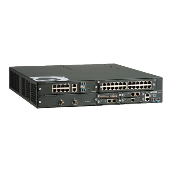
Nortel Secure 4134 Quick Start Manual
Nortel secure 4134: quick start
Hide thumbs
Also See for Secure 4134:
- Configuration (260 pages) ,
- Installation manual (132 pages) ,
- Installation — hardware components (124 pages)
Table of Contents
Advertisement
Quick Links
Advertisement
Table of Contents

Related Manuals for Nortel Secure 4134


Summary of Contents for Nortel Secure 4134
- Page 1 Nortel Secure Router 4134 Quick Start NN47263-100 (323245-A)
-
Page 2: Restricted Rights Legend
In the interest of improving internal design, operational function, and/or reliability, Nortel Networks reserves the right to make changes to the products described in this document without notice. Nortel Networks does not assume any liability that may occur due to the use or application of the product(s) or circuit layout(s) described herein. -
Page 3: Canadian Department Of Communications Radio Interference Regulations
CE marking statement (Europe only) EN 55022 statements This is to certify that the Nortel Secure Router 4134 equipment is shielded against the generation of radio interference in accordance with the application of Council Directive 89/336/EEC. Conformity is declared by the application of EN 55022 Class A (CISPR 22). - Page 4 National Safety Statements of Compliance EN 60950 statement This is to certify that the Nortel Secure Router 4134 equipment is in compliance with the requirements of EN 60950 in accordance with the Low Voltage Directive. Additional national differences for all European Union countries have...
- Page 5 Norma Oficial Méxicana (NOM): Exporter: Nortel Networks, 5400 Hellyer Ave, San Jose, CA 95138 USA. Importer: Nortel Networks de México, S.A. de C.V. Avenida Insurgentes Sur #1605 Piso 30, Oficina Col. San Jose Insurgentes Deleg-Benito Juarez México D.F. 03900 Tel:...
-
Page 6: National Environmental Statements Of Compliance
This section explains how to get help for Nortel products and services. Getting help from the Nortel web site The best way to get technical support for Nortel products is from the Nortel Technical Support web site: www.nortel.com This site provides quick access to software, documentation, bulletins, and tools to address issues with Nortel products. -
Page 7: Getting Help Through A Nortel Distributor Or Reseller
Getting help over the phone from a Nortel Solutions Center If you do not find the information you require on the Nortel Technical Support web site, and have a Nortel support contract, you can also get help over the phone from a Nortel Solutions Center. - Page 8 Bedingung vermeidet, die kann Ursache ernste Personenschäden oder Tod. Cautions and warnings for the Secure Router 4134 The following precautionary messages apply to the Secure Router 4134. For your safety, read these precautions carefully before proceeding with installation of the product.
- Page 9 The Lithium battery in this product is part of a non-volatile memory device and will retain data for 10 years in the absence of power. Nortel does not consider the lithium battery in this unit a field replaceable or serviceable part and should not be accessed by the customer.
-
Page 10: Personal Safety And Equipment Protection
Personal safety and equipment protection Read this section to prevent injury and equipment damage. Module protection The following practices prevent equipment damage when you work on the Nortel Secure Router 4134: • Always wear a grounded antistatic wrist strap when you handle modules. -
Page 11: Electrostatic Discharge
Electrostatic discharge Electrostatic discharge (ESD) is the transfer of charge between objects at different electrical potentials. ESD can change the electrical characteristics of a semiconductor device, and degrade or destroy it. ESD can cause equipment to malfunction or fail. To dissipate or neutralize electrostatic charges, use proper grounding and use conductive or dissipative materials. Use a grounded ESD wrist strap. -
Page 13: Table Of Contents
Installing or removing an internal VPN/IPSec module 36 Installing the internal VPN/IPSec module 36 Prerequisites 36 Removing the internal VPN/IPSec module 38 Prerequisites 39 Connecting power cables 40 Copyright © 2007, Nortel Networks Nortel Secure Router 4134 Quick Start NN47263-100 01.01 Standard 10.0 16 July 2007... - Page 14 Class A device caution statement 57 Qualified service personnel warning statement 58 Overcurrent warning statement 59 Cover plate warning statement 60 Power cord warning statement 61 Copyright © 2007, Nortel Networks Nortel Secure Router 4134 Quick Start NN47263-100 01.01 Standard 10.0 16 July 2007...
-
Page 15: New In This Release
New in this release The following section details what’s new in the Nortel Secure Router 4134 — Quick Start (NN47263-100) for Release 10.0. Features See the following sections for information about feature changes: • "Secure Router 4134 chassis" (page 15) •... -
Page 16: Ac And Dc Power Supplies
16 New in this release AC and DC power supplies The Secure Router 4134 has two slots for power supply modules. You can install single or dual power supply modules in any of the following configurations: • one or two standard AC input modules •... -
Page 17: Introduction
Introduction Nortel Secure Router 4134 — Quick Start (NN47263-100) provides basic instruction on how to install the hardware and perform initial configuration of the Nortel Secure Router 4134. The Quick Start is intended for experienced installers. Navigation • "Installing the Secure Router 4134 chassis and hardware components"... - Page 18 18 Introduction Nortel Secure Router 4134 Quick Start NN47263-100 01.01 Standard 10.0 16 July 2007 Copyright © 2007, Nortel Networks...
-
Page 19: Secure Router 4134 Installation And Initial Configuration
Secure Router 4134 installation and initial configuration Install the Secure Router 4134 and log on to prepare the unit for configuration and deployment in your network. Secure Router 4134 installation and initial configuration tasks This work flow shows you the sequence of tasks you perform to install the Secure Router 4134 and prepare the unit for system configuration. -
Page 20: Secure Router 4134 Installation And Initial Configuration Navigation
Figure 1 Secure Router 4134 installation and initial configuration tasks Secure Router 4134 installation and initial configuration navigation • "Unpacking and inspecting the Secure Router 4134 chassis" (page 23) • "Installing a power supply module" (page 24) • "Installing the mounting brackets on the chassis" (page 25) •... - Page 21 "Connecting a terminal for local access" (page 49) • "Establishing remote access" (page 50) • "Changing the default administrator password" (page 52) Copyright © 2007, Nortel Networks Nortel Secure Router 4134 Quick Start NN47263-100 01.01 Standard 10.0 16 July 2007...
- Page 22 22 Secure Router 4134 installation and initial configuration Nortel Secure Router 4134 Quick Start NN47263-100 01.01 Standard 10.0 16 July 2007 Copyright © 2007, Nortel Networks...
-
Page 23: Installing The Secure Router 4134 Chassis And Hardware Components
Remove the shipping container. Place the chassis on antistatic material. Check all items for damage. If you detect any damage, do not install the chassis. Call the Nortel Technical Solutions Center in your area. Copyright © 2007, Nortel Networks —End—... -
Page 24: Installing A Power Supply Module
24 Installing the Secure Router 4134 chassis and hardware components The following table lists the accessories you can find in the shipping container with the Secure Router 4134. Place a mark in the third column of the table to verify that you have received each accessory. -
Page 25: Prerequisites
You must install the mounting brackets on the Secure Router 4134 before installing the chassis in an equipment rack. You can mount the Secure Router 4134 with either the front panel or the back panel facing the operator. The following table shows the six possible mounting positions. - Page 26 26 Installing the Secure Router 4134 chassis and hardware components Average time to install mounting brackets: 2 minutes. Table 2 Mounting bracket installation options Position Position 1 with front panel facing operator Position 2 with front panel facing operator Position 3 with front panel...
-
Page 27: Prerequisites
Secure Router 4134. Use a #2 Phillips screwdriver to attach a bracket to the desired mounting position on one side of the Secure Router 4134. Torque the mounting bracket screws to 3 to 6 in-lb (0.339 to 0.6779 N-m). -
Page 28: Installing The Chassis
You must install the Secure Router 4134 in a restricted-access location. You must limit access to the Secure Router 4134 to authorized service personnel only. Nortel recommends that you install the chassis (including the power supplies and fan tray) in the equipment rack before you install the ground lug and the optional external interface modules. -
Page 29: Grounding The Chassis
Ensure the mounting brackets are firmly installed on the chassis. • Ensure you have appropriate antistatic materials. • Nortel recommends you have two people to help lift the chassis into the equipment rack and securing it. • Ensure your installation site meets the physical, electrical, and... -
Page 30: Prerequisites
30 Installing the Secure Router 4134 chassis and hardware components You must install the Secure Router 4134 in a restricted-access location. You must limit access to the Secure Router 4134 to authorized service personnel only. Prerequisites • Ensure you have the terminal lug and the associated screws and washers that shipped with the Secure Router 4134 chassis (two 8-32 x .187”... - Page 31 Secure the ground lug with two 8-32 screws and washers (provided), ensuring the barrel faces down, as shown in the following figure. Copyright © 2007, Nortel Networks CAUTION Vorsicht Als allgemeine Sicherheitsanweisung stellen Sie Sie zur Verfügung stellen DC Spannung sicher durch entweder eine Sicherung oder DC Circuit breaker mit einer maximalen Bewertung von 12 Amps.
-
Page 32: Installing The Interface Modules
Slot numbering on the Secure Router 4134 A slot numbering legend is printed directly above the chassis SFP Ethernet ports (ports 0/3 and 0/4) on the front panel of the Secure Router 4134. The legend shows how slots are numbered on the Secure Router 4134. The following figure shows the slot numbering legend. -
Page 33: Prerequisites
If you insert a Large Module, it spans slots 6 and 7. If you install a Large Module, slots 6 and 7 become slot 6. For detailed information about the Secure Router 4134 modules, see Nortel Secure Router 4134 Installation — Hardware Components (NN47263-301). -
Page 34: Installing A Small Module
34 Installing the Secure Router 4134 chassis and hardware components Installing a Small Module Use the procedure in this section to install a Small Module in the Secure Router 4134. You can install Small Modules in slots 1, 2, 3, and 4. Procedure steps Step... -
Page 35: Installing A Large Module
Installing a Large Module Use the procedure in this section to install a Large Module in the Secure Router 4134. You can install a Large Module to span slots 6 and 7 only. Procedure steps Step Action Use a Phillips screwdriver to remove the slot cover plates from slots 6 and 7. -
Page 36: Installing Or Removing An Internal Vpn/Ipsec Module
Use the instructions in this section to install, remove, or replace the internal VPN/IPSec module. This internal module is not hot-swappable. If you ordered the VPN/IPSec module with your Secure Router 4134, the Secure Router ships with the VPN/IPSec module installed. - Page 37 Procedure steps Step Action Remove the two screws at the rear of the Secure Router 4134 that hold the service access panel secure. Remove these two screws only. See the following figure. Slowly slide the access panel toward you until it is clear of the Secure Router 4134.
-
Page 38: Removing The Internal Vpn/Ipsec Module
Secure Router 4134. Copyright © 2007, Nortel Networks —End— CAUTION The internal VPN/IPSec module is not hot-swappable. Do not open the Secure Router 4134 service access panel while the unit is powered. Nortel Secure Router 4134 Quick Start NN47263-100 01.01 Standard... -
Page 39: Prerequisites
Procedure steps Step Action Remove the two screws at the rear of the Secure Router 4134 that hold the service access panel secure. Remove these two screws only. See the following figure. Slide the access panel toward you until it is clear of the Secure Router 4134. -
Page 40: Connecting Power Cables
40 Installing the Secure Router 4134 chassis and hardware components Grasping the edges of the VPN/IPSec module, pull the module up and out of the slot in which it is seated. If you are not installing a VPN/IPSec module at this time, replace the service access panel. -
Page 41: Connecting Ac Power Cables
Action Insert the female end of an appropriately rated AC power cord in the AC receptacle on the rear panel of the Secure Router 4134, as shown in the following figure. Insert the male end of the power cord in a standard 110/220 V AC power outlet. -
Page 42: Connecting Dc Power
42 Installing the Secure Router 4134 chassis and hardware components Connecting DC power The following figure shows the location of the terminal block on the DC power supply module. Figure 3 Secure Router 4134 DC power supply terminal block Average time to install one DC power cable: 3 minutes. - Page 43 Switch off the DC power source. Loosen both terminal cover screws on the DC power supply, as shown in the following figure. Copyright © 2007, Nortel Networks CAUTION As a general safety precaution, ensure you provide DC power through either a fuse or DC circuit breaker with a maximum rating of 12 amps.
- Page 44 44 Installing the Secure Router 4134 chassis and hardware components Remove the terminal cover to expose the terminal block. Insert the –48 V lead behind the –48 V terminal, as shown in the following figure. Copyright © 2007, Nortel Networks...
- Page 45 first tie within six inches of the terminal block. Position the bound wires to prevent accidental contact when passing by the Secure Router 4134. Attach the other ends of the leads to a –48 V DC power source. Copyright © 2007, Nortel Networks —End— Nortel Secure Router 4134 Quick Start NN47263-100 01.01 Standard...
-
Page 46: Powering Up The Router
The fan tray red (fail) LED can illuminate briefly while the fans power to operational speed. If status LEDs do not illuminate green, see Nortel Secure Router 4134 — Troubleshooting (NN47263-700). Verifying a successful installation Use the information in this section to verify that you have successfully installed the Secure Router 4134 and its components. - Page 47 As a general rule, an LED illuminates green for items that you installed. If the SM and MM LEDs on the rear panel of the Secure Router 4134 do not illuminate green, refer to the LEDs on the modules to identify issues.
- Page 48 48 Installing the Secure Router 4134 chassis and hardware components Nortel Secure Router 4134 Quick Start NN47263-100 01.01 Standard 10.0 16 July 2007 Copyright © 2007, Nortel Networks...
-
Page 49: Configuring The Secure Router 4134 For Remote Access
Configuring the Secure Router 4134 for remote access You must connect a local terminal and log on to the Secure Router 4134 to initially configure the system. Connecting a terminal for local access You use the console port to initially configure the system. The following figure shows the location of the console port on the rear panel of the Secure... -
Page 50: Establishing Remote Access
PC. Power up the Secure Router 4134. Establishing remote access The first time you log on to the Secure Router 4134 CLI, you perform initial configuration such as the following: 1. Configure the IP address for the management port. -
Page 51: Using Ssh For Remote Access
Ethernet port 0/0 is a 10/100 Base-T port. Ethernet ports 0/1 and 0/2 are 10/100/1000 Base-T ports. Procedure steps Step Action To log on to the Secure Router 4134 CLI for the first time, enter the default user name and password: login: password: To access configuration mode, enter:... -
Page 52: Changing The Default Administrator Password
Commissioning (NN47263-302). To configure features on your Secure Router 4134, see Nortel Secure Router 4134 — Documentation Roadmap (NN47263-103) for a list of Nortel Secure Router 4134 documents and information about the Release 10.0 features. Changing the default administrator password Nortel recommends that you change the default administrator password for security reasons. - Page 53 Enter your new password. The Secure Router 4134 prompts you to verify the new password. Re-enter your new password. A message appears that confirms that the password is changed. Copyright © 2007, Nortel Networks Changing the default administrator password 53 —End—...
- Page 54 54 Configuring the Secure Router 4134 for remote access Nortel Secure Router 4134 Quick Start NN47263-100 01.01 Standard 10.0 16 July 2007 Copyright © 2007, Nortel Networks...
-
Page 55: Environmental Requirements
Install the Secure Router 4134 in a restricted-access location. Limit access to the Nortel Secure Router 4134 to authorized service personnel only. Ensure you allow 2 to 3 feet (0.61 to 0.91 m) of additional clearance around the Secure Router 4134 for access to the cable connectors on the front and rear panels. - Page 56 Parameter Storage altitude Operating humidity Storage humidity Vibration Acoustic noise Copyright © 2007, Nortel Networks Range 0–35 000 ft (0–11 000 m) 0 to 90% R.H. (noncondensing) 0 to 95% R.H. (noncondensing) Packaging and shipping – ISTA 2A Office Vibration – GR-63-CORE Issue 3, Section 4.4.2 and 5.4.2...
-
Page 57: Translations Of Safety Messages
Appendix Translations of safety messages Class A device caution statement Copyright © 2007, Nortel Networks CAUTION This device is a Class A product. Operation of this equipment in a residential area is likely to cause harmful interference, in which case users will be required to take whatever measures may be necessary to correct the interference at their own expense. -
Page 58: Qualified Service Personnel Warning Statement
58 Appendix Translations of safety messages Qualified service personnel warning statement Copyright © 2007, Nortel Networks CAUTION Cuidado Este dispositivo é uma Classe UM produto. Operação deste equipamento em uma área residencial é provável causar interferência prejudicial no qual caso que serão exigidos os usuários que levem qualquer medidas pode ser necessário corrigir... -
Page 59: Overcurrent Warning Statement
Overcurrent warning statement Copyright © 2007, Nortel Networks Overcurrent warning statement 59 WARNING Aviso Sólo puede realizar la instalación personal cualificado de asistencia técnica. Lea y siga todas las notas de advertencia e instrucciones indicadas en el producto o incluidas en la documentación. -
Page 60: Cover Plate Warning Statement
60 Appendix Translations of safety messages Cover plate warning statement Copyright © 2007, Nortel Networks WARNING Aviso El interruptor Secure Router 4134 está protegido contra las sobrecargas de corriente mediante la instalación del edificio. Asegúrese de utilizar un fusible o un disyuntor que no supere los 120 VAC, 15A en EE.UU. -
Page 61: Power Cord Warning Statement
Power cord warning statement Copyright © 2007, Nortel Networks CAUTION Achtung Wenn Sie kein Modul im Schacht verwenden, muß die Metallabdeckung über dem Schacht montiert sein. Eine Entfernung der Abdeckung führt zu einer Verschlechterung der Luftzirkulation und damit zu einer nicht ausreichenden Kühlung der Einheit. -
Page 62: Nortel Secure Router
62 Appendix Translations of safety messages Copyright © 2007, Nortel Networks DANGER Danger N’utilisez que des cordons d’alimentation équipés de trajet de mise à la terre. Sans mise à la terre adaptée, vous risquez de recevoir une décharge électrique en touchant le commutateur. - Page 64 This document is protected by copyright laws and international treaties. All information, copyrights and any other intellectual property rights contained in this document are the property of Nortel Networks. Except as expressly authorized in writing by Nortel Networks, the holder is granted no rights to use the information contained herein and this document shall not be published, copied, produced or reproduced, modified, translated, compiled, distributed, displayed or transmitted, in whole or part, in any form or media.