ADC HiGain H2TU-C-319 List 4E User Manual
Adc higain h2tu-c-319 list 4e line unit user manual
Hide thumbs
Also See for HiGain H2TU-C-319 List 4E:
- Quick installation (7 pages) ,
- Manual (2 pages) ,
- User manual (80 pages)

Related Manuals for ADC HiGain H2TU-C-319 List 4E


Summary of Contents for ADC HiGain H2TU-C-319 List 4E
- Page 1 HiGain HiGain HiGain HDSL2 SETUP STATUS H2TU-C-319 List 4E Product Catalog: H2TU-C-L4E CLEI Code: VACHYVYG ANUAL...
- Page 2 Contents herein are current as of the date of publication. ADC reserves the right to change the contents without prior notice. In no event shall ADC be liable for any damages resulting from loss of data, loss of use, or loss of profits, and ADC further disclaims any and all liability for indirect, incidental, special, consequential or other similar damages.
- Page 3 Unpack each container and inspect the contents for signs of damage. If the equipment has been damaged in transit, immediately report the extent of damage to the transportation company and to ADC DSL Systems, Inc. Order replacement equipment, if necessary.
- Page 4 Inspecting Shipment LTPH-UM-1049-02, Issue 2 January 9, 2002 H2TU-C-319 List 4E...
-
Page 5: Table Of Contents
LTPH-UM-1049-02, Issue 2 ABLE OF ONTENTS Overview ____________________________________________________________________________ 1 Features ...1 Compatibility ...2 Applications ...2 Front Panel __________________________________________________________________________ 3 Installation___________________________________________________________________________ 8 Verification ...9 Verification without an H2TU-R Remote Unit ...9 Verification with an H2TU-R Remote Unit ...9 Provisioning_________________________________________________________________________ 10 Using the MODE and LBK Pushbuttons ...10 Setting Options through MODE and LBK ...10 Resetting to Factory Default Values...11 Displaying System Parameter Settings...11... - Page 6 Table of Contents Testing _____________________________________________________________________________ 52 System Alarms... 52 Alarm Option for the Digital Loop Carrier Feed ... 53 Retiring System Alarms ... 53 Remote LOS and AIS Response ... 54 OCT55 Test Pattern with AMI Line Code ... 54 Loopback Operation ...
- Page 7 5. Inventory Screen...15 6. Config Menu...16 7. Config Menu - Standard Options (defaults shown)...17 8. Config Menu - ADC Options (defaults shown) ...17 9. Metallic Test Access Block Diagram ...28 10. MTA Relays ...29 11. Metallic Test Access TB6 on HMS-358 Backplane...29 12.
- Page 8 4. Logon Screen Menus... 13 5. H2TU-C-319 List 4E Standard Config Menu Options ... 18 6. H2TU-C-319 List 4E ADC Config Menu Options ... 19 7. DS1 and DSX-1 24-hour PM Threshold ... 22 8. Response to H2TU-R DS1 Frame Conversion Options... 24 9.
-
Page 9: Overview
LTPH-UM-1049-02, Issue 2 VERVIEW The H2TU-C-319 List 4E (H2TU-C) line unit is the Central Office (CO) side of a T1 transmission system. The HiGain HDSL2 product family is fully compliant with the HDSL2 standard ANSI T1.418. Providing full-rate T1 access using a single copper pair, HDSL2 is a cost-effective solution that offers an open architecture. The open architecture inherent in HDSL2 guarantees interoperability allowing simple and economic accommodation of network growth. -
Page 10: Ltph-Um-1049-02, Issue
The H2TU-C has two unique features, Metallic Test Access and Dual DS1 port options, which are not provided in standard ADC line units with 3192 mechanics. These features require additional access pins which are provided by a special card-edge connector, shown in accommodate this special connector. -
Page 11: Front Panel
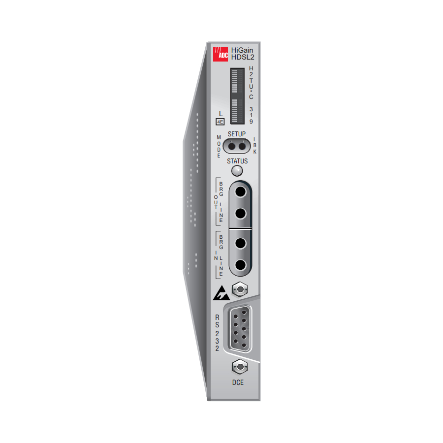
LTPH-UM-1049-02, Issue 2 RONT ANEL Figure 1 shows the H2TU-C-319 List 4E front panel. pinout diagrams of the H2TU-C-319 List 4E card-edge connector and craft port, refer to Specifications” on page Card handle (CLEI code and ECI bar code label on outside of handle) Figure 1. -
Page 12: Front-Panel Description
Front Panel Front-Panel Feature Function Front-panel display Displays four-character status, provisioning, and alarm system messages. The front-panel display illuminates when power is initially applied. To conserve power the display only remains on for 5 minutes. Using the MODE or LBK pushbuttons reactivates the display and restarts the 5-minute timer. -
Page 13: Front-Panel Display Messages
LTPH-UM-1049-02, Issue 2 Table 2 lists the front-panel display messages. The four-character display reports the code of an alarm, loopback, or diagnostic message and, in some cases, is followed by a second four-character message that modifies the first message with a value or current configuration setting. Message Full Name ALARM MESSAGES... - Page 14 Front Panel Table 2. Front-Panel Display Messages (Continued) Message Full Name LOOPBACK MESSAGES CLOC Customer Local Loopback CREM Customer Remote Loopback NLOC Network Local Loopback NREM Network Remote Loopback SMJK Remote SmartJack Loopback DIAGNOSTIC MESSAGES A = xx Maximum Loop Attenuation Acquisition HiGain System Armed BAD RT?
- Page 15 LTPH-UM-1049-02, Issue 2 Table 2. Front-Panel Display Messages (Continued) Message Full Name SYSTEM INFORMATION MESSAGES CODE xxxx Line Code: AMI or B8ZS FRM xxxx Frame: SF, ESF, or UNFR LATT xx Loop Attenuation LIST xx H2TU-C List Number MARG xx Margin VER x.xx H2TU-C Software Version Number...
-
Page 16: Installation
Upon receipt of the equipment, inspect the contents for signs of damage. If the equipment has been damaged in transit, immediately report the extent of damage to the transportation company and to ADC. H2TU-C-319 Figure 2. Installing the H2TU-C-319 List 4E into a Shelf When installing an H2TU-C in a chassis, be sure to wear an antistatic wrist strap. -
Page 17: January
LTPH-UM-1049-02, Issue 2 ERIFICATION Once the H2TU-C is installed, verify that it is operating properly. To do this, monitor the following: • Status LED • Status messages reported by the front-panel display Verification without an H2TU-R Remote Unit If there is no H2TU-R remote unit installed: Verify that the H2TU-C powers up. -
Page 18: Provisioning
Provisioning ROVISIONING There are two provisioning methods: • Use the MODE and LBK pushbuttons on the front panel of the H2TU-C to: – Set system options – Reset the H2TU-C to its factory default settings for system options – Display system option settings (scroll mode) –... -
Page 19: Resetting To Factory Default Values
LTPH-UM-1049-02, Issue 2 Resetting to Factory Default Values All user options for the H2TU-C, described in the MODE and LBK pushbuttons. To set the user options to their default values: Press the LBK pushbutton for 6 seconds until the following message appears: DFLT NO Press the LBK pushbutton until the DFLT NO message is displayed. -
Page 20: Using A Maintenance Terminal
Provisioning SING A AINTENANCE Connecting to a Maintenance Terminal The craft port on the front panel allows you to connect the H2TU-C to a maintenance terminal (ASCII terminal or PC running a terminal emulation program). Once connected to a maintenance terminal, you can access the maintenance, provisioning, and performance screens. -
Page 21: Logon Screen
Identifies the 100 most recent system events and reports the date and time of occurrence. Provides standard configuration options, ADC options, date and time setting, and a reset option (factory settings). Also provides a master clear option that clears all performance, alarm, and event log entries. -
Page 22: Provisioning Tasks
“Configuring the System” on page 33). Event Log Config Inventory Report +-----------------------+ | Standard Options -> | | ADC Options -> | | Test Mode -> | Date and Time -> +---------------------------------+ | Date (mm/dd/yyyy) : | Time (hh:mm[:ss]) : 06:40:11... -
Page 23: Setting Circuit Id Numbers
LTPH-UM-1049-02, Issue 2 Setting Circuit ID Numbers The Inventory menu provides product information on all units in the system and allows setting of the circuit and unit identification numbers. Monitor Performance -------------------------- Unit : H2TU-C Product : H2TU-C-319 List : 4E Sw Ver. -
Page 24: Configuring The System
Figure 8 on page 17 supported by HiGain HDSL2 units when connected to units from other vendors. ADC options are an extended set of options that are only available when using HiGain units exclusively. For a description of each option and a list... -
Page 25: Config Menu - Standard Options (Defaults Shown)
Figure 7. Config Menu - Standard Options (defaults shown) Monitor Performance Use <Spacebar> to cycle through option settings and <Enter> to activate ID: xxxx--xxxx--xxxx--xxxx Figure 8. Config Menu - ADC Options (defaults shown) H2TU-C-319 List 4E Event Log Config Inventory... -
Page 26: H2Tu-C-319 List 4E Standard Config Menu Options
Table 5 describes the Standard Config screen options and lists their front-panel display codes. describes the ADC Config screen options and lists their front-panel display codes. Selections in bold typeface are the factory default settings. Table 5. H2TU-C-319 List 4E Standard Config Menu Options... -
Page 27: H2Tu-C-319 List 4E Adc Config Menu Options
Table 5. H2TU-C-319 List 4E Standard Config Menu Options (Continued) Front-Panel Standard Config Display Selection Menu Options Code Power Back Off PBOC Customer Table 6. H2TU-C-319 List 4E ADC Config Menu Options Front-Panel ADC Config Menu Display Selection Options Code Line Power Feed PWRF Remote Provisioning RTPV... - Page 28 Provisioning Table 6. H2TU-C-319 List 4E ADC Config Menu Options (Continued) Front-Panel ADC Config Menu Display Selection Options Code Minor Alarm Network AIS Signal NAIS Performance Report SPRM Messaging NPRM S + N SF RAI to SF RAI-CI RACI Toward Network “SF RAI to SF...
- Page 29 LTPH-UM-1049-02, Issue 2 Table 6. H2TU-C-319 List 4E ADC Config Menu Options (Continued) Front-Panel ADC Config Menu Display Selection Options Code Active DS1 Port ADS1 “Dual DSX-1 Port Option” on page CTHR H2TU-C-319 List 4E Description The MUX mode selects the DSX-1 (MUX) port as the active source for the DS1 Signal to transmit to the HSDL Line Port #1.
-
Page 30: Ds1 And Dsx-1 24-Hour Pm Threshold
Provisioning HDSL2 BER Threshold (HBER) Option. The HBER option permits the monitoring of loop integrity and reporting of alarms when excessive errors are detected. The PM primitive used for this purpose is the CRC checksum performed on the HDSL2 frame for both directions of transmission. It is, therefore, called a block error rate rather than the bit error rate associated with the DS1 interface. - Page 31 LTPH-UM-1049-02, Issue 2 SF RAI to SF RAI-CI Toward Network (RACI) Option. In general, the Remote Alarm Indication - Customer Installation (RAI-CI) signal is a RAI signal which contains a signature indicating that an LOF or AIS failure has occurred within the customer’s network. RAI-CI is transmitted toward the network when these two conditions are simultaneously true at the point from which RAI-CI is originated (at the H2TU-R, toward the network): •...
-
Page 32: Response To H2Tu-R Ds1 Frame Conversion Options
Provisioning used to embed SPRM or NPRM into the datalink toward the network. During conversion, frame bit errors are regenerated to ensure transparency. The HDSL2 system attempts to find ESF or SF framing or determines that no framing exists. The DS1 framing is then synchronized with the HDSL2 frame. -
Page 33: Extended Superframe Format
LTPH-UM-1049-02, Issue 2 Framing Pattern ESF Number Sequence (FPS) - 2 kps SF Number H2TU-C-319 List 4E Table 9. Extended SuperFrame Format Frame Bits Frame Bit for Datalink (FDL) - 4 kbps Table 10. SuperFrame Format Frame Bits Terminal Framing Bit SuperFrame Signaling Bit January 9, 2002 Provisioning... -
Page 34: Dds Ni And Ds0 Dp Latching Loopback Sequence
Provisioning Fractional T1 (FT1) Option. Fractional T1 circuits can be used in feeder networks to provide frame relay service. If such circuits are maintained by a DDS test group, then these circuits must respond to DDS/DS0 latching loopback commands, the only tool test groups have at their disposal. A latching loopback, once it has been initiated by the correct sequence, remains locked or “latched”... -
Page 35: Response Of H2Tu-C-319 List 4E And H2Tu-R To Los And Ais
LTPH-UM-1049-02, Issue 2 a successful loopdown is reported; otherwise, a failed loopdown is reported. The loop-down can also be initiated by depressing the H2TU-R loopback control button or by any of the standard 3-in-5 loop-down commands. The implemented detection/release loopback algorithm functions properly in the presence of a 10 Since the FT1 mode is a combination of both the full T1 and the latching loopback modes, all codes are always active. -
Page 36: Metallic Test Access Block Diagram
Provisioning Test Access The H2TU-C’s PC board’s card-edge connector, shown in labeled S1 (segment 1), S2 (segment 2), and S3 (segment 3). S3 contains the standard 3192 pin connections. The two extra segments, S1 and S2, have pin connections that support additional features called Dual DSX-1 port option and Metallic Test Access (MTA), respectively, as shown in Cable Golden... -
Page 37: Mta Relays
LTPH-UM-1049-02, Issue 2 Metallic Test Access. Figure 9 on page 28 are under control of the two relays, K1 and K2. The S2 metallic test access ports (IN or OUT) are bused to terminal block TB6 located on the HMS-358 backplane, as shown in TB6 on the HMS-358 backplane. -
Page 38: H2Tu-C-319 List 4E Block Diagram
Provisioning The MTAF IN port of TB6 can connect to an external test facility circuit consisting of an HDSL2 wire line simulator or test pair and a golden H2TU-R remote HDSL2 unit. This connection allows the H2TU-C Unit Under Test (UUT) to be tested from its DSX-1 interface on the simulated test circuit. This allows any problem to be isolated to either the equipment or the facilities. - Page 39 LTPH-UM-1049-02, Issue 2 The separate control of K1 and K2 permits another test scenario. Two external HDSL2 spans can be looped together at TB6 if the two H2TU-C line units that connect to the two spans both enable their MTAF states and close K1 in each unit.
-
Page 40: Config Menu - Reset To Factory Defaults
Figure 13. Config Menu - Reset to Factory Defaults to cancel this action. Event Log Config Inventory Report +-----------------------+ | Standard Options -> | | ADC Options -> | | Test Mode -> | | Date and Time -> | | Master Clear Set Factory Defaults +-----------------------+... -
Page 41: Clearing The History, Alarm, And Event Log Screens
H2TU-C-319 List 4E Event Log Config Inventory Report +-----------------------+ | Standard Options -> | | ADC Options -> | | Test Mode -> | | Date and Time -> | Master Clear | Set Factory Defaults +-----------------------+... -
Page 42: Monitoring System Activity And Performance
Monitoring System Activity and Performance ONITORING ERFORMANCE The H2TU-C-319 List 4E provides the following maintenance screens for monitoring system activity and assessing performance: • The Monitor screens provide a graphical representation of circuit activity and allow initiation of loopbacks. • The Performance screens provide current, 24-hour, 48-hour, and 31-day performance histories and a continuous alarm history. -
Page 43: Using The Monitor Screen To View System Activity
LTPH-UM-1049-02, Issue 2 SING THE ONITOR Press to view the system diagram. Figure 15 shows an armed circuit with an active loopback and alarms. Terms used on the system diagram are defined in the onscreen Help menu glossary. Abnormal situations are highlighted on the diagram. on page 36 describes the screen field. -
Page 44: Monitor Screen Descriptions
Monitoring System Activity and Performance Field Description Active Loopback An active loopback is indicated on the lower third of the Monitor screen. Available loopbacks are indicated by gray text. See loopback codes and activation methods. Alarm Type Indicates type of alarm. Armed Mode Indicates system is in an armed state and ready for an intelligent repeater (IR) loopback command. -
Page 45: Using The Performance Screens To View Performance Data
LTPH-UM-1049-02, Issue 2 SING THE ERFORMANCE The Performance screens display: • CRC statistics for the HDSL2 or DS1 interface in 31-day, 48-hour, 25-hour, and current history reports. • Alarm statistics for the DS1 interfaces (Figure 26 on page 45) on a continuous basis. To access the performance history screens: Press to select the Performance screen. -
Page 46: Performance History At The Ds1 Interface
Monitoring System Activity and Performance Performance History at the DS1 Interface The Performance History for the DS1 interface provides 31-day, 48-hour, 25-hour, and current statistics screens for the H2TU-C and the H2TU-R (as viewed from the H2TU-C). Figure 16 below and Figure 17 on page 38 Figure 18 on page 39 is an example of DS1 performance history screens at the line unit. -
Page 47: H2Tu-C Ds1 48-Hour Performance History
LTPH-UM-1049-02, Issue 2 Monitor Performance ------------------------------------------------------------------------------ Time CV-L ES-L *00:00 *01:00 *02:00 *03:00 *04:00 *05:00 *06:00 *07:00 *08:00 *09:00 *10:00 *11:00 Press: (N)ext Page, (P)revious Page, C(l)ear History ----------------------------------------------------------------------------- Use <Space> to cycle through choices and <Enter> to view ID: xxxx--xxxx--xxxx--xxxx 08/01/2001 07:05:33 Figure 18. -
Page 48: Performance History At The Hdsl2 Interface
Monitoring System Activity and Performance Performance History at the HDSL2 Interface The HDSL2 interface has 31-day, 48-hour, 25-hour, and current statistic screens for the H2TU-C. Figure 20 below are examples of 31-day and 48-hour performance history screens. example of a 25-hour performance history screen. Refer to errors reported on all HDSL2 performance screens. -
Page 49: H2Tu-C Hdsl2 25-Hour Performance History
LTPH-UM-1049-02, Issue 2 Monitor Performance ------------------------------------------------------------------------------ Time *22:15 *22:30 *22:45 *23:00 23:15 23:30 23:45 00:00 00:15 00:30 00:45 01:00 Press: (N)ext Page, (P)revious Page, C(l)ear History ----------------------------------------------------------------------------- Use <Space> to cycle through choices and <Enter> to view ID: xxxx--xxxx--xxxx--xxxx 08/01/2001 07:05:33 Figure 21. -
Page 50: Current Statistics Screens For The Ds1 Interface
Monitoring System Activity and Performance Current Statistics Screens for the DS1 Interface Examples of current statistics screens are shown below. interface at the remote unit and line unit, respectively. These screens report 1-day, 1-hour, and 15-minute statistics. Refer to Table 15 on page 39 for descriptions of the kinds of errors reported on these screens. -
Page 51: Current Statistics For Hdsl2 Interface
LTPH-UM-1049-02, Issue 2 Current Statistics for HDSL2 Interface Figure 24 shows statistics for the HDSL2 interface at the H2TU-C. This screen reports 1-day, 1-hour, and 15-minute statistics. Refer to Table 16 on page 41 Monitor Performance Event Log ----------------------------------------------------------------------------- 1 Day 1 Hour Start 00:00... -
Page 52: Using The Performance Screens To View Alarm Data
Monitoring System Activity and Performance SING THE ERFORMANCE To access the alarm history screens: Press to select the Performance menu. Press the SPACEBAR to select an interface (H2TU-C DS1, H2TU-R DS1, H2TU-C HDSL2, or H2TU-R HDSL2), then press Press the SPACEBAR until Alarm History is selected, then press •... -
Page 53: H2Tu-R Ds1 Alarm History Screen
LTPH-UM-1049-02, Issue 2 Monitor Performance Event Log ----------------------------------------------------------------------------- Alarm First RLOS RAIS TX RAI-CI PRM-NE PRM-FE DBER 08/16/01 00:37 ------------------------------------------------------------------------------ Use <Space> to cycle through choices and <Enter> to view ID: xxxx--xxxx--xxxx--xxxx Figure 26. H2TU-R DS1 Alarm History Screen Screen Alarm Front-Panel Alarm Description H2TU-C DSI Alarms (see Figure 25 on page SPTE... -
Page 54: Alarm History At The Hdsl2 Interface
Monitoring System Activity and Performance Table 17. DS1 Alarm Descriptions (Continued) Screen Alarm Front-Panel Alarm Description DBER xxx-DBER Bit Error Rate—The DS1 BER has exceeded the built-in 24-hour threshold limits of approximately 10 (a) This is a DS1-specific alarm that also issues a minor alarm (sent to the management unit or the backplane), if enabled. (b) AIS-CI is a modified AIS alarm pattern. -
Page 55: Hdsl2 Alarm Descriptions
LTPH-UM-1049-02, Issue 2 Screen Alarm Front-Panel Alarm MTAE MTAE MTAF MTAF LOSW LOSW xxx-MAL xxx-LA HBER xxx-HBER SHORT PWR FEED SHRT PWR FEED GND OPEN PWR FEED OPEN (a) Displays only on the H2TU-C HDSL2 interface. H2TU-C-319 List 4E Table 18. HDSL2 Alarm Descriptions Description Metallic Test Access Equipment—The H2TU-C is in its MTA/LOSW test state. -
Page 56: Using The System Event Log To Track Events
Monitoring System Activity and Performance SING THE YSTEM To view a running log of system events, press time of the 100 most recent events (most recent displayed first) and provides a description of each event. on page 49 lists the event log messages. •... -
Page 57: Event Log Entry Messages List
LTPH-UM-1049-02, Issue 2 Any DS1 Alarm History reset Any DS1 PM register reset Any HDSL2 Alarm History reset Any HDSL2 PM register reset Any Loop Down (any segment) Any Loop Up (any segment) Any provisioning option change: <provisioning mnemonic>: changed from <old> to <new> CPE DBER alarm (1-day threshold crossed of any PM data except PRM-NE or PRM-FE) CPE DS1 AIS begins/ends CPE DS1 LOS begins/ends... -
Page 58: Using The Report Menu
Monitoring System Activity and Performance SING THE EPORT The Report menu (Figure 29) provides screens containing status and performance monitoring data for line and remote units which can be downloaded to a file for analysis or future reference. four types of reports provided by the Report menu. To select each individual report, do the following: Press to select Report menu. -
Page 59: Report Types
LTPH-UM-1049-02, Issue 2 Type Full Report Short Report System Information Report Event Report H2TU-C-319 List 4E Monitoring System Activity and Performance Table 20. Report Types Contains the following information: • Circuit and unit identifications • Product information • System configuration •... -
Page 60: Testing
Testing ESTING This section provides information about front-panel system alarms, LOS and AIS response, OCT55 test procedure, and loopback testing. YSTEM LARMS Table 21 summarizes all possible system alarms in order of priority as they appear on the front panel. When multiple alarms occur, the front-panel display only reports the highest priority alarm. -
Page 61: Alarm Option For The Digital Loop Carrier Feed
LTPH-UM-1049-02, Issue 2 Table 21. Front-Panel System Alarms Summary (Continued) Front-Panel Alarm Message xxx-HBER HDSL2 Block Error Rate xxx-MAL Margin Alarm xxx-LA Loop Attenuation (a) The message, ALRM, displays prior to any alarm message. (b) Only these alarms assert the System Alarm bus on pin H of the card edge connector, if the alarm system is set to ENABLE. (c) When the HDSL2 loop loses sync word (LOSW), a system alarm condition exists. -
Page 62: Remote Los And Ais Response
19. See Table 13 on page 27 LOS event? Remove alarm AIS event? pattern ADC Option Standard Option Default configurations are in bold. Figure 30. H2TU-R LOS and AIS Response Priorities OCT55 T ATTERN WITH The OCT55 test pattern can be used in unframed mode to stress the system and verify data integrity. In an SF or ESF framing mode, excessive zero anomalies may occur, which causes the H2TU-C to report ES, SES, and UAS errors according to ANSI T1.231-1997. -
Page 63: Loopback Operation
LTPH-UM-1049-02, Issue 2 OOPBACK PERATION HiGain HDSL2 has a family of loopback options for analyzing circuit functionality. The loopback signal is transmitted and returned to the sending device for comparison. This allows you to verify the integrity of the HDSL2 channels to the H2TU-C, the H2TU-C DSX-1 interface and the DS1 channels to the customer. Loopback options include: •... -
Page 64: Generic Loopback Commands
Special Loopback Commands In addition to the GNLB loopback command mode, a HiGain HDSL2 system can be configured for one of three special loopback command modes. These are selected from the maintenance terminal Config menu, ADC Options screen (see Table 5 on page... -
Page 65: Smartjack Loopback Commands
LTPH-UM-1049-02, Issue 2 SmartJack Loopback Commands The HiGain HDSL2 SmartJack (SMJK) Loopback (LPBK) commands allow you to use in-band, out-of-band, and universal codes to initiate and terminate loopback testing of the HiGain HDSL2 circuit. (See Procedure” on page 64 for additional information.) ANUAL OOPBACK A manual loopback session allows you to select any one of the HiGain HDSL2 loopbacks listed in... -
Page 66: Activating Manual Metallic Test Access
Testing Press LBK to activate NLOC. The display changes to MAN LPBK NLOC. Press MODE to advance to the next available loopback: • NRE? = NREM • CRE? = CREM • CLO? = CLOC Press LBK to activate the selected loopback. The previous loopback is terminated. Once a loopback is selected and activated, the loopback stays active until it times out (based on the LBTO setting). -
Page 67: In-Band Loopback Sessions
LTPH-UM-1049-02, Issue 2 You can also manually terminate the MTA state and exit the MAN LPBK mode by simultaneously pressing the MODE and LBK pushbuttons for 3 or more seconds. If no loopback or MTA is active, the MAN LPBK mode automatically terminates after 30 seconds. -
Page 68: Loopback Modes
Testing H2TU-C H2TU-C H2TU-C FF1E NLOC D3D3 ‡ 1111000 4-in-7 H2TU-C 3F1E CREM D3D3 ‡ 1111110 All ones 6-in-7 H2TU-C All ones H2TU-C * Set the NLBP option to AIS to send AIS (indicated by an all ones pattern) for any network loopback. A3LB and A4LB loopback codes. -
Page 69: A2Lb Test Procedures
LTPH-UM-1049-02, Issue 2 A2LB Test Procedures Using the codes listed in Table enabled). A tester at the customer premises can activate CLOC or CREM loopbacks. All loopbacks shown in Table 23 can also be initiated from the H2TU-C front-panel MODE and LBK pushbuttons (see through MODE and LBK”... - Page 70 H2TU-C generates 231 (NLOC and CREM) ID bit errors. As a result, the H2TU-C may indicate one more or one less bit error, depending on the test set type and the number of frame bits contained in the block of errored bits. To avoid this uncertainty, ADC recommends sending unframed IR commands.
- Page 71 LTPH-UM-1049-02, Issue 2 The Time-out Override function is only valid for the current active loopback. The automatic time-out timer is restored during subsequent loopback sessions. Once the test is complete, do one of the following: • If the system is to loopdown but remain Armed, send the IR (Intelligent Repeater) LPDN code for universal loopdown.
-
Page 72: A3Lb And A4Lb Test Procedures
Testing A3LB and A4LB Test Procedures The H2TU-C can be looped back by sending the Addressable Office Repeater (AOR) LPBK activation code 1111-1111-0001-1110 (FF1E) for at least 5 seconds. This causes the H2TU-C to enter the NLOC state. The Loopback Time-out setting (see this loopback unless it is overridden by the reception of a second identical 16-bit loopup command before the timer expires. -
Page 73: Appendix A - Specifications
LTPH-UM-1049-02, Issue 2 A - S PPENDIX Power HDSL2 Span Voltage CO Supply Electrical Protection Fusing Environmental Operating Temperature Operating Humidity Physical Height Width Depth Weight Mounting HDSL2 Line Code Transmission Media Output Line Impedance Maximum Provisioning Loss Start-up Time DSX-1 DSX-1 Line Impedance DSX-1 Pulse Output... -
Page 74: Power Consumption
Appendix A - Specifications OWER ONSUMPTION The three most important power parameters of an H2TU-C are its maximum power consumption, maximum power dissipation, and maximum current drain. Table 26 describes line-powered circuits on 9 kft, 26 AWG loops without a regenerator. Table 26. -
Page 75: Loop Attenuation, Insertion Loss, And Reach
LTPH-UM-1049-02, Issue 2 TTENUATION Each loop has no more than 35 dB of loss at 196 kHz, with driving and terminating impedances of 135 , as shown Table 27 below. This is equivalent to no more than 28 dB loop attenuation. Insertion Loss Cable Gauge 196 kHz (dB/kft) -
Page 76: H2Tu-C-319 List 4E Card-Edge Connector
Appendix A - Specifications H2TU-C-319 L 4E C Figure 33 shows the pin assignments of the card-edge connector on the H2TU-C-319 List 4E card. The function of its segments (S1, S2, and S3) are described beginning with Standard 3192 alphanumeric connector pins to Segment 3 (A through L and 1 through 10) are labeled on the backplane of the HMS-358 shelf. -
Page 77: Network Management Control Bus
The H2TU-C provides a Network Management Control Bus on pin 7 of the card-edge connector. This allows the various ADC Management System protocols to manage the H2TU-C through the HMU-319 HiGain Management Unit. Whenever the H2TU-C is under management, the MNGD message displays periodically on the front-panel display. -
Page 78: System Alarm Output Pin
Appendix A - Specifications System Alarm Output Pin Pin H on the card-edge connector, shown in notes apply to pin H: • Pin H replaces the Local Loss of Signal (LLOS) on normal high-density (3192) repeaters. • The normally floating output of pin H can connect to pin 1 of the 1184 or 3192-9F Alarm Card in position 29 of the high density (HD) shelf. -
Page 79: Craft Port
LTPH-UM-1049-02, Issue 2 RAFT Figure 35 shows the pinout for the craft port connector and its connection to a DB-9 or DB-25 connector on a maintenance terminal. H2TU-C-319 DB-9 Connector (DCE) H2TU-C-319 List 4E TD (Transmit Data) RD (Receive Data) Figure 35. -
Page 80: Appendix B - Functional Operation
B - F PPENDIX ADC HDSL2 technology provides full-duplex services at standard DS1 rates over copper wires between an H2TU-C and an H2TU-R, which comprise one HiGain HDSL2 system. HiGain HDSL2 systems use ADC Overlapped Pulse Amplitude Modulation (PAM) Transmission with Interlocking Spectra (OPTIS) transceiver systems to establish full-duplex, 1.552 kbps data channels between the H2TU-C and a remotely located H2TU-R. -
Page 81: Timing
LTPH-UM-1049-02, Issue 2 IMING The low loop wander (0.3 UI max) of an H2TU-C, when used with compatible regenerators and remote units, allows the circuit to be used in all critical timing applications, including those that are used to transport Stratum 1 timing. -
Page 82: Appendixc - Compatibility
August 1999 T1-E1.4/99-006R5 HDSL2 standards. The H2TU-C are designed to mount in the following shelves with 3192 mechanics: • ADC HMS-317 (28-slot, 23-inch shelf) • ADC HHS-319 (3-slot, 19-inch horizontal shelf) • ADC HMS-308 (8-slot remote enclosure) • Charles Ind. #3192 (28-slot connectorized) •... -
Page 83: Appendixd - Product Support
ADC Customer Service Group provides expert pre-sales and post-sales support and training for all its products. ECHNICAL UPPORT Technical support is available 24 hours a day, 7 days a week by contacting the ADC Technical Assistance Center (TAC) at one of the following numbers: •... -
Page 84: Appendix E - Abbreviations
Appendix E - Abbreviations E - A PPENDIX ACO: Alarm Cutoff ACON: Auto Conversion of DS1 frame ACQ: Acquisition ADSI: Active DSX-1 AIS: Alarm Indication Signal ALRM: Alarm Condition AMI: Alternate Mark Inversion AUX: Auxiliary AWG: American Wire Gauge B8ZS: Bipolar with 8-Zero Substitution BER: Bit Error Rate BPVT: Bipolar Violation Transparency... - Page 85 LTPH-UM-1049-02, Issue 2 MTAE: Metallic Test Access Equipment MTAF: Metallic Test Access Facilities MUX: Multiplexer NLOC: Network Local Loopback NMA: Network Management and Administration NPRM: Network PRM NREM: Network Remote Loopback OPTIS: Overlapped PAM Transmission with Interlocking Spectra PAM: Pulse Amplitude Modulation PRM: Performance Report Messaging PRMF: Performance Report Messaging - Far End PRM-FE: Performance Report Messaging - Far End...
- Page 86 Appendix E - Abbreviations LTPH-UM-1049-02, Issue 2 January 9, 2002 H2TU-C-319 List 4E...
-
Page 87: Certification And Warranty
ADC during the 90-day warranty period is, at ADC’s option, either (a) return of the price paid or (b) repair or replace of the software. ADC also warrants that, for a period of thirty (30) days from the date of purchase, the media on which software is stored will be free from material defects under normal use. - Page 88 ADC DSL Systems, Inc. 14402 Franklin Avenue Tustin, CA 92780-7013 Tel: 714.832.9922 Fax: 714.832.9924 Technical Assistance Tel: 800.638.0031 Tel: 714.730.3222 Fax: 714.730.2400 : LTPH-UM-1049-02, I OCUMENT SSUE ISO 9001/TL 9000 ´,-Q¶6o¨ DNV Certification, Inc. REGISTERED FIRM 1213496...