Metra Electronics 99-3010S Installation Instructions Manual
For chevrolet camaro2010-2015
Hide thumbs
Also See for 99-3010S:
- Installation instructions manual (16 pages) ,
- Installation instructions manual (8 pages)
Table of Contents
Advertisement
Quick Links
KIT COMPONENTS
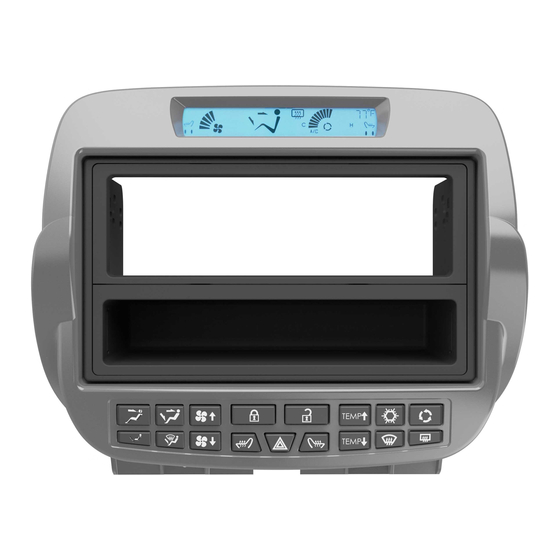
• A) Radio trim panel with climate controls • B) Radio housing • C) Pocket • D) ISO DDIN brackets • E) ISO DDIN trim plate • F) ISO trim plate
• G) ISO brackets • H) Axxess interface and harness (not shown)
A
Metra. The World's Best Kits.
®
Chevrolet Camaro 2010-2015
KIT FEATURES
• DIN radio provision with pocket
• ISO DIN radio provision with pocket
• ISO DDIN radio provision
• Painted silver to match the factory finish
B
C
F
MetraOnline.com
D
E
G
© COPYRIGHT 2018 METRA ELECTRONICS CORPORATION
99-3010S
I N S TA L L AT I O N I N S T R U C T I O N S
TABLE OF CONTENTS
Dash Disassembly . ..............................................2-3
Kit Preparation . ......................................................3
Kit Assembly
–DIN radio provision with pocket ........................4
–ISO DIN radio provision with pocket . .................4
–ISO DDIN radio provision . ....................................5
Axxess Interface Installation . ................................6
WIRING & ANTENNA CONNECTIONS
Wiring Harness: Axxess interface included
Antenna Adapter: 40-EU55 (sold sep.)
Steering wheel control interface: ASWC-1 (sold sep.)
Backup camera retention: BACKUPCAM-2 (sold sep.)
TOOLS REQUIRED
• Panel removal tool • Phillips screwdriver
• 9/32" socket wrench • T-20 Torx screwdriver
• Cutting tool
CAUTION!
All accessories, switches, climate
controls panels, and especially air bag indicator
lights must be connected before cycling the
ignition. Also, do not remove the factory radio
with the key in the on position, or while the
vehicle is running.
REV. 5/25/18 INST99-3010S
Advertisement
Table of Contents

Related Manuals for Metra Electronics 99-3010S


Summary of Contents for Metra Electronics 99-3010S
- Page 1 Also, do not remove the factory radio with the key in the on position, or while the vehicle is running. Metra. The World’s Best Kits. MetraOnline.com ® © COPYRIGHT 2018 METRA ELECTRONICS CORPORATION REV. 5/25/18 INST99-3010S...
- Page 2 DASH DISASSEMBLY For vehicles without UMQ gauge panel, 4. Remove (2) Phillips screws exposed unsnap and remove shifter trim panel under the cover on the back of console. and skip to step 8. (Figure D) 5. Remove gauge cluster/trim panel 1. Unclip and remove the (2) side trim panels running the length of the center around shifter. (Figure E) console. (Figure A) 6. Auto transmission vehicles only: 2. Remove (1) Phillips screw from each Remove one T-20 Torx screw from the (Figure A) (Figure D) front of the shifter, and then remove side of the front of the center console.
-
Page 3: Kit Preparation
DASH DISASSEMBLY KIT PREPARATION 7. Remove (4) Phillips screws now 1. Cut and remove the sub dash radio exposed, and then lift up on the rear support to make room for the interface of the center console. Slide toward and harnesses. (Figure A) the back of the vehicle then unclip 2. Remove the panel clips from the factory and remove the entire center console. radio, then attach them to the 99-3010S Remove shaded area (Figure G) radio trim panel with climate controls. 8. Remove (2) 9/32” screws securing the (Figure B) climate control/radio trim panel and (Figure G) remove. (Figure H) Continue to Kit Assembly 9. Remove (4) 9/32” screws securing the radio chassis, and then remove. (Figure A) -
Page 4: Iso Din Radio Provision With Pocket
KIT ASSEMBLY DIN radio provision with pocket ISO DIN radio provision with pocket 1. Remove the metal DIN sleeve from the 1. Remove the metal DIN sleeve and trim aftermarket radio. ring from the aftermarket radio. 2. Slide the sleeve into the top opening 2. Secure the ISO brackets to the radio of the radio housing and secure by using the screws supplied with the bending the metal locking tabs down. radio. (Figure A) (Figure A) 3. Snap the pocket into the bottom (Figure A) 3. Snap the pocket into the bottom opening of the radio housing. opening of the radio housing. (Figure B) (Figure B) 4. Slide the radio into the top opening of... -
Page 5: Iso Ddin Radio Provision
KIT ASSEMBLY ISO DDIN radio provision Remove shaded area 1. Cut and remove the center support. (Figure A) 2. Snap the ISO DDIN brackets to the inside edge of the radio housing. (Figure B) 3. Slide the radio into the bracket/radio housing assembly, then secure it using the screws supplied with the radio. (Figure C) (Figure A) (Figure B) (Figure C) 4. Snap the ISO DDIN trim plate into the radio housing. (Figure C) Continue to Axxess Interface Installation. REV. -
Page 6: Table Of Contents
AXXESS INTERFACE INSTALLATION INTERFACE FEATURES TABLE OF CONTENTS • Provides accessory power (12-volt 10-amp) Connections to be made ......................7-10 • Maintains the Retained Accessory Power (R.A.P.) feature For models without an amplifier ..................7-8 • Provides NAV outputs (parking brake, reverse, speed sense) For models with an amplifier ..................... 8-9 • Retains warning chimes Installing the Axxess interface and climate controls ..............10 • Retains OnStar/OE Bluetooth Programming the Axxess interface and climate controls ............10 • Adjustable volume for chimes and OnStar Adjusting the Axxess interface ....................11 • Retains the factory AUX-IN jack Final assembly ..........................11 • Pre-wired ASWC-1 harness (ASWC-1 sold separately) Configure backlight color . -
Page 7: Connections To Be Made
CONNECTIONS TO BE MADE Attention! This interface will work with models that are either non-amplified or amplified, • Connect the Green/Purple wire to the reverse wire. Please follow the instructions carefully for your model vehicle. Failure to do so will result in • Connect the Light Green wire to the parking brake wire. either no sound, or low sound. If you are unsure if your vehicle is factory amplified or not, • Tape off and disregard the following (5) wires, they will not be used in this application: please contact your local dealership. Blue/White, Purple, Purple/Black, Green, Green/Black For models without an amplifier: From the 3010 harness to the aftermarket radio: From the 16-pin harness with stripped leads to the aftermarket radio: • Connect the Black wire to the ground wire. -
Page 8: For Models With An Amplifier
CONNECTIONS TO BE MADE (CONT.) For models with an amplifier: • The Black/Yellow wire is used for OnStar level adjustment for models that do not come equipped with steering wheel controls. Refer to the OnStar level Adjustment section for From the 16-pin harness with stripped leads to the aftermarket radio: further instructions. • Connect the Red wire to the accessory wire. Attention! If this wire is not connected the climate control will fail to function. Note: If installing either an ASWC-1 or AX-LCD (both sold separately), connect the (2) • Connect the Pink wire with a red bullet connector to the Pink wire from the climate Red wires from the 3010 harness as well. control harness. • Connect the Blue/White wire to the amp turn on wire. This wire must be connected to hear • If retaining the factory AUX-IN jack is desired, connect the Red and White RCA jacks to the sound from the factory amplifier. audio AUX-IN jacks from the aftermarket radio. - Page 9 CONNECTIONS TO BE MADE (CONT.) • Tape off and disregard the following (4) wires, they will not be used in this application: • If retaining the factory AUX-IN jack is desired, connect the Red and White RCA jacks to the Green, Green/Black, Purple, Purple/Black audio AUX-IN jacks from the aftermarket radio. Note: a) The jack can only be used if it is a single jack. From the 3010 harness to the aftermarket radio: b) If the jack has a USB port as well, neither can be retained. • Connect the Black wire to the ground wire. Note: The relay attached to the 3010 harness is only for audible turn signal clicks. • Connect the Yellow wire to the battery wire. No extra steps are required to retain this feature, so leave the relay as-is. • If installing either an ASWC-1 or AX-LCD (both sold separately), connect the (2) Red wires to accessory power. 12-pin pre-wired ASWC-1 harness: • Connect the Green wire to the left rear positive speaker output. This harness is to be used along with the optional ASWC-1 (sold separately) to retain steering • Connect the Green/Black wire to the left rear negative speaker output.
-
Page 10: Installing The Axxess Interface And Climate Controls
A xxess interface. 1. Start the vehicle. 2. Connect the climate control harness to the radio trim panel with climate controls, then to 2. Connect the 3010 harness to the wiring harness in the vehicle. The L.E.D. will initially be solid the wiring harness in the vehicle. Green to indicate the interface is powered. 3. Locate the factory antenna connector in the dash and complete all necessary connections to 3. After a few seconds the L.E.D. will turn solid Red while the interface automatically programs the radio. Metra recommends using the proper antenna adapter from Metra. to the vehicle. The radio will shut off at this point. This process should take 5 to 30 seconds. 4. If an ASWC-1 (sold separately) will be used, do not connect it until the 99-3010S is 4. Once the interface has been programmed the L.E.D. will turn solid Green, then the radio will programmed and fully functional. come back on, indicating programming was successful. Attention! Do not connect the 3010 harness to the wiring harness in the vehicle just yet. Programming the climate display: If the interface ever loses power, the following steps will need to be performed again. Please ensure that the owner of the vehicle knows this. 5. Ensure that the vehicle is still running. 6. Adjust the fan speed on the climate control all the way up, then all the way down. -
Page 11: Adjusting The Axxess Interface
• If the vehicle doesn’t come equipped with steering wheel controls, locate the Black/Yellow Blue Green wire on the 3010 harness. Color level up • While OnStar is speaking, tap the Black/Yellow wire to ground. Once the OnStar level is set, Color level down it will stay at that level until the Black/Yellow wire is tapped to ground again Press and hold to enter “Configure backlight color” mode TROUBLESHOOTING FINAL ASSEMBLY Resetting the Axxess interface 1. The Blue reset button is located inside the Axxess interface, between the two connectors. 1. Secure the radio assembly to the dash using the factory screws. The button is accessible outside the Axxess interface, no need to open the Axxess interface. 2. Reassemble the dash in reverse order of disassembly using the 99-3010S radio trim panel 2. Press and hold the reset button for two seconds, then let go to reset the Axxess interface. with climate controls to complete the installation. 3. Refer to “Programming the Axxess Interface” from this point. REV. 5/25/2018 INST99-3010S... - Page 12 Log onto www.installerinstitute.com or call 800-354-6782 for more information and take steps toward a better tomorrow. Metra recommends MECP certified technicians Metra. The World’s Best Kits. MetraOnline.com ® © COPYRIGHT 2018 METRA ELECTRONICS CORPORATION REV. 5/25/18 INST99-3010S...