Barco G60 Installation Manual
Hide thumbs
Also See for G60:
- User manual (64 pages) ,
- Safety manual (13 pages) ,
- Installation manual (22 pages)
Table of Contents
Advertisement
Quick Links
Advertisement
Table of Contents

Related Manuals for Barco G60


Summary of Contents for Barco G60
- Page 1 Installation manual ENABLING BRIGHT OUTCOMES...
- Page 2 Barco NV Beneluxpark 21, 8500 Kortrijk, Belgium www.barco.com/en/support www.barco.com Registered address: Barco NV President Kennedypark 35, 8500 Kortrijk, Belgium www.barco.com/en/support www.barco.com...
- Page 3 Barco. Changes Barco provides this manual 'as is' without warranty of any kind, either expressed or implied, including but not limited to the implied warranties or merchantability and fitness for a particular purpose. Barco may make improvements and/or changes to the product(s) and/or the program(s) described in this publication at any time without notice.
-
Page 5: Table Of Contents
Table of contents 1 Introduction...........................................7 Installation Requirements ................................8 Projector package overview................................9 Main unit.........................................10 Input/Output (I/O) Panel................................11 Control panel .......................................12 Remote Control Unit (RCU) ................................13 Lenses........................................13 2 Installation ..........................................17 RCU battery installation ................................18 Installing the lens ....................................18 Connecting the projector with the power net ........................20 Connecting to a computer or laptop ............................21 Connecting to video sources ..............................22 Ceiling mount installation ................................22... - Page 6 R5910887 /00...
-
Page 7: Introduction
Clarification of the term “G60” used in this document When referring in this document to the term “G60” means that the content is applicable for following Barco products: •... -
Page 8: Installation Requirements
Introduction 1.1 Installation Requirements Environment conditions Table below summarizes the physical environment in which the G60 projector may be safely operated or stored. Operating Non-Operating Environment Ambient Temperature 5 °C (41 °F) to 40 °C (104 °F) -10°C (14°F) to 60°C (140°F) -
Page 9: Projector Package Overview
Introduction Main power requirements The G60 projector operates from a nominal mono phase power net with a separate earth ground PE. Projector Power requirements G60-W7 AC INPUT 100-240V, 50/60Hz G60-W8 AC INPUT 100-240V, 50/60Hz G60-W10 AC INPUT 100-240V, 50/60Hz The power cord required to connect the projector with the power net is delivered with the projector. -
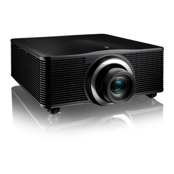
Page 10: Main Unit
Introduction The projection lens is an optional item, not a standard accessary in the package. Due to the difference in applications for each country, some regions may have different accessories. 1.3 Main unit Component location Image 1-7 Remote receiver (Front) Projection lens Image 1-8 LED Status Indicator... -
Page 11: Input/Output (I/O) Panel
Introduction Airflow Image 1-9 1.4 Input/Output (I/O) Panel Input and output ports location DVI-D VGA-IN HDBas eT 3D SYNC IN HDMI-1 HDMI-2 3G-SDI mini USB US B Type-A VGA-OUT RS-232 R E MOTE I N 3D SYNC OUT Image 1-10 3D SYNC IN Networking connector RJ45 HDBaseT connector... -
Page 12: Control Panel
Introduction 1.5 Control panel Button location MENU EXIT INPUT LENS FOCUS ENTER Image 1-11 POWER ZOOM LENS FOCUS MENU LEFT EXIT ENTER DOWN INPUT RIGHT Button function Button Function POWER Turn the projector on or off. LENS Adjust lens position. MENU Show the main menu on screen. -
Page 13: Remote Control Unit (Rcu)
Select a specific function set as the hot key. Pattern Display test patterns. 1.7 Lenses The table below is subject to changes and was last updated on 2019-01-03. Consult Barco's web site for the most recent information about available lenses. R5910887 /00... - Page 14 Image Order No Throw Ratio R9832781 G Lens - Short Throw 0.75 - 0.95 : 1 (WUXGA) (includes lens ring for G60-W series) R9832755 G Lens - Wide zoom 0.95 - 1.22 : 1 (WUXGA) R9801784 G Lens - Standard 1.22 - 1.52 : 1 (WUXGA)
- Page 15 Introduction R9801785 R9832755 R9801784 R9832756 R9832778 R9832781 Projection Lens Ultra Short Ultra Long Short Long Zoom Wide Zoom Standard Throw Zoom Throw Throw Ratio 0.361 (120") 0.95-1.22 1.22-1.52 1.52-2.92 2.90-5.50 0.75-0.95 Zoom Ratio 1.28X 1.25X 1.9X 1.9X 1.26X Throw Distance 0.96~3.01m 1.01~7.98m 1.30~9.96m...
- Page 16 Introduction R5910887 /00...
-
Page 17: Installation
Installation Overview • RCU battery installation • Installing the lens • Connecting the projector with the power net • Connecting to a computer or laptop • Connecting to video sources • Ceiling mount installation R5910887 /00... -
Page 18: Rcu Battery Installation
Installation 2.1 RCU battery installation How to install the batteries of the Remote Control Unit Remove the cover by sliding it in the direction indicated by the arrow Insert two new AAA batteries (observe the polarity). Replace the cover. Image 2-1 Notes for the Remote Control Unit •... - Page 19 Installation Image 2-2 Gently insert the lens in the lens holder. Ensure that the label “TOP” (reference 1) is upwards oriented while inserting the lens. Image 2-3 Rotate the lens clockwise to lock the lens. Image 2-4 Put the lens ring on the lens. An audible click should be noticed. Image 2-5 CAUTION: Do not transport the projector with any lens installed.
-
Page 20: Connecting The Projector With The Power Net
Installation 2.3 Connecting the projector with the power net CAUTION: Use only the power cord provided with the projector. How to connect with local power net Ensure that the power switch stands in the '0' (OFF) position (reference 1) Connect the female side of the power cord with the power input socket of the projector (reference 2) Image 2-6 Connect the male side of the power cord to the local power net. -
Page 21: Connecting To A Computer Or Laptop
Installation 2.4 Connecting to a computer or laptop Wiring diagram Image 2-7 USB cable RS232 cable Mini USB cable VGA in cable HDMI cable VGA out cable DVI cable Notes on wiring diagram: • The diagram shows the cables/connectors that may be used to connect to various devices. •... -
Page 22: Connecting To Video Sources
2.6 Ceiling mount installation Requirements To prevent damage to your projector, please use a Barco recommended ceiling mount. Ensure the screws used to install the mount to the projector meet the following specifications: • Screw type: M6 x 4 •... - Page 23 Installation 280.0 140.0 100.0 100.0 310.0 310.0 99.0 99.0 4 - M6 x1.0P L10 280.0 Image 2-9: Dimensions given in millimeters. Damage resulting from incorrect installation will void the warranty. R5910887 /00...
- Page 24 Installation R5910887 /00...
-
Page 25: Powering On/Off The Projector
Powering On/Off the projector This chapter assumes that the power cord and (all) signal cables are securely connected. For detailed instructions see installation manual. Overview • Powering On the projector • Powering Off the Projector R5910887 /00... -
Page 26: Powering On The Projector
Powering On/Off the projector 3.1 Powering On the projector How to power On the projector Power on the AC switch (1) and wait until the power button on the control panel is solid red. Image 3-1 Turn on the projector by pressing the POWER button (2) on the control panel or the ON key (3) on the remote control. - Page 27 Powering On/Off the projector MENU EXIT INPUT LENS FOCUS ENTER Image 3-4 Press the POWER button or OFF key again to confirm, otherwise the message disappears after 5 seconds and the projector remains on. CAUTION: Don’t turn on the projector immediately after entering Standby mode. R5910887 /00...
- Page 28 Powering On/Off the projector R5910887 /00...
-
Page 29: Adjusting The Projected Image
Adjusting the projected image Overview • Adjusting the projector’s position • Adjusting the image position on the screen R5910887 /00... -
Page 30: Adjusting The Projector's Position
Within these shift ranges the projector and lens perform excellently. Configuring the projector outside these shift ranges will result in a slight decline of image quality. G60 Vertical Shift range: 100% G60 Horizontal Shift range: 30% R5910887 /00... - Page 31 Adjusting the projected image +100% +100% -30% +30% -100% -30% -100% +30% Image 4-2 Field of view See user guide for instructions on how to shift the lens holder (Screen Menu > Horz/Vert Position) R5910887 /00...
- Page 32 Adjusting the projected image R5910887 /00...
-
Page 33: A Communication Protocols
Communication protocols R5910887 /00... -
Page 34: Serial Control
Communication protocols A.1 Serial control RS232 Configuration RS232 protocol 115200 bps (default) Baud Rate Data Length 8 bit Parity Check None Stop Bit 1 bit Flow Control None RS232 protocol table (v00.14) Level 1 Level 2 Level 3 Level 4 Level 5 Default Uart Command... - Page 35 Communication protocols Level 1 Level 2 Level 3 Level 4 Level 5 Default Uart Command Gain 1 ~ 199 [ H G G G * Blue 1~199 [ H G B H * Satura- 0 ~ 199 [ H G B S * tion Gain 1 ~ 199...
- Page 36 Communication protocols Level 1 Level 2 Level 3 Level 4 Level 5 Default Uart Command source detect Vert 0 ~ 100 depend [ V P O S * Position analog source detect Digital 0 ~ 10 [ H D Z M * Horz Zoom Digital...
- Page 37 Communication protocols Level 1 Level 2 Level 3 Level 4 Level 5 Default Uart Command [ B L C X [ B L C X [ B L C X Bottom [ B L C Y Left Vert Adjust [ B L C Y [ B L C Y [ B L C Y Bottom...
- Page 38 Communication protocols Level 1 Level 2 Level 3 Level 4 Level 5 Default Uart Command Bottom [ P P P G 2 Left Bottom [ P P P G 3 Right Size Large Medium [ P H S G 2 Medium [ P H S G 1 Small...
- Page 39 Communication protocols Level 1 Level 2 Level 3 Level 4 Level 5 Default Uart Command Russian L A N G 7 Spanish L A N G 8 Portuguese L A N G 9 Indonesian L A N G 1 0 Dutch L A N G 1 1 Menu...
- Page 40 Communication protocols Level 1 Level 2 Level 3 Level 4 Level 5 Default Uart Command Constant 0 to 99 L P P W * Power Light LD Hours L S H S ? Source Info Options Back- Logo Logo [ B G C L 0 ground Blue [ B G C L 1...
- Page 41 Name Serial Number Native Resolution MCU FW DDP FW M9813 FW Motor FW LAN FW Front end LD Driver G60-W10 only Main Input Main Signal Format Main Pixel Clock Main Sync Type Main Horz Refresh Main Vert Refresh PIP/PBP...
- Page 42 Communication protocols Level 1 Level 2 Level 3 Level 4 Level 5 Default Uart Command PIP/PBP Pixel Clock PIP/PBP Sync Type PIP/PBP Horz Refresh PIP/PBP Vert Refresh Light Source Power Light Source Hours Standby Mode Lens Lock Settings IP Address DHCP System Tempera-...
- Page 43 Communication protocols Level 1 Level 2 Level 3 Level 4 Level 5 Default Uart Command Subnet L S U B "***.***.***. Mask ***" Default L G A T "***.***.***. Gateway ***" L M A C ? Address Apply Com- L A P Y 1 mand Network Projector By set...
-
Page 44: Lan
Communication protocols KEYG 60 Mode KEYG 36 Auto KEYG 41 Input KEYG 46 KEYG 10 Left KEYG 11 Enter KEYG 12 Right KEYG 13 Down KEYG 14 Menu KEYG 20 Exit KEYG 72 Gamma KEYG 61 Bright KEYG 19 Cont. KEYG 62 KEYG 63 Lens H(Left) - Page 45 Communication protocols Creston command list Type Item Join Number Assign To Name Serial 5051 Brightness Level Analog 5002 Brightness Minus Digital 5110 Brightness Plus Digital 5109 Color Level Analog 5001 Color Minus Digital 5108 Color Plus Digital 5107 Contrast Level Analog 5003 Contrast Minus...
- Page 46 Communication protocols Type Item Join Number Right Digital 5154 Sharpness Level Analog 5004 Sharpness Minus Digital 5114 Sharpness Plus Digital 5113 Source Name 1 (read only) Serial 5070 Source Name 2 (read only) Serial 5071 Source Name 3 (read only) Serial 5072 Source Name 4 (read only)
- Page 47 Communication protocols Description Command Video Mute Query [PMUT?] [FREZ1] Freeze Freeze Query [FREZ?] [MSRC#] Main Source Main Source Query [MSRC?] [SSRC#] Sub Source Sub Source Query [SSRC?] Aspect Ratio [ASPR#] Aspect Ratio Query [ASPR?] Display Mode [DPMO#] Display Mode Query [DPMO?] R5910887 /00...
- Page 48 Communication protocols R5910887 /00...
-
Page 49: Index
Index Adjustments 29 Position 30 Power 25 Power cord 20 Power Off 26 Power On 26 Box content 9 RCU 13 Ceiling mount 22 Battery 18 Communication protocols 33 Connections 21 Control panel 12 Serial control 34 Shift range 30 Input/Output 11 Install Lens 18... - Page 50 R5910887 /00 | 2019-01-31 Barco NV | Beneluxpark 21, 8500 Kortrijk, Belgium Registered address: Barco NV | President Kennedypark 35, 8500 Kortrijk, Belgium www.barco.com...