Carrier 48LC Series Controls, Start-Up, Operation And Troubleshooting
Single package rooftop units with systemvu controls version 2.x and puron r-410a refrigerant
Hide thumbs
Also See for 48LC Series:
- Controls, start-up, operation and troubleshooting (190 pages) ,
- Service and maintenance instructions (76 pages) ,
- Installation instructions manual (76 pages)
Table of Contents
Advertisement
Quick Links
48/50LC 04---26
Single Package Rooftop Units
with SystemVu™ Controls Version 2.X
and Puronr (R---410A) Refrigerant
IMPORTANT: This literature covers 48/50LC 04- -26 models with SystemVu controls version 2.X (factory- -installed option).
. . . . . . . . . . . . . . . . . . . . . . . . . . . . . . . . . . . . . . . . .
. . . . . . . . . . . . . . . . . . . . . . . . . . . . . . . . . .
. . . . . . . . . . . . . . . . . . . . . . . . . . . . . . . . .
. . . . . . . . . . . . . . . . . . . . . . . . . . . . .
. . . . . . . . . . . . . . . . . . . . . . . . . . . . . . . . . . . . . . . . .
. . . . . . . . . . . . . . . . . . . . . . . . . . . . . . . . . . . .
. . . . . . . . . . . . . . . . . . . . . . . . . . . . .
. . . . . . . . . . . . . . . . . . . . . . . . . . . . . . . . . . .
. . . . . . . . . . . . . . . . . . . . . . . . . . . . . . . .
. . . . . . . . . . . . . . . . . . . . . . . . . . . . . . . . . . . . .
. . . . . . . . . . . . . . . . . . . . . . . . . . . . . . . . . . . . .
. . . . . . . . . . . . . . . . . . . . . . . . . . . . . . . . . . . .
Controls, Start-- Up, Operation
and Troubleshooting
TABLE OF CONTENTS
. . . . . . . . . . . . . . . . . . . . . . . . .
. . . . . . . . . . . . . . . . . . . . . .
. . . . . . . . . . . . . . . . . . . . . . . . . . .
. . . . . . . . . . . . . . . . . . . . . . . .
. . . . . . . . . . . . . . . .
Page
2
3
3
3
3
3
4
5
. . . . . . . . . . . . . . . . . . . . . . . . . . . . . . . . . . . . . .
5
6
6
6
6
6
6
6
. . . . . . . . . . . . . . . . . . . . . . . . . . . . . . . . . . . . . .
6
1
. . . . . . . . . . . . . . . . . . . . . . . . . . .
. . . . . . . . . . . . . . . . . . . . . . . . . . . . . . . . . .
. . . . . . . . . . . . . . . . . . . . . . . . . . . .
. . . . . . . . . . . . . . . . . . . . . . . . . . . . . . .
. . . . . . . . . . . . . . . . . . . . . . . . . . . . . . . . . . .
. . . . . . . . . . . . . . . . . . . . . . . . .
. . . . . . . . . . . . . . . . .
. . . . . . . . . . . . . . . . . . . . . . . . . . . . . . . . .
. . . . . . . . . . . . . . . . . . . . . . . . . . . . .
. . . . . . . . . . . . . . . . . . . . . . . . . . . .
. . . . . . . . . . . . . . . . . . . . . .
. . . . . . . . . . . . . . . . . . . . . . . . . . . . . .
. . . . . . . . . . . . . . . . . . . . . . . . . . . . . .
C150173
7
7
7
7
8
9
9
9
9
9
9
9
10
10
. . . . . . . . . .
10
10
Advertisement
Table of Contents
Troubleshooting

Related Manuals for Carrier 48LC Series


Summary of Contents for Carrier 48LC Series
-
Page 1: Table Of Contents
48/50LC 04---26 Single Package Rooftop Units with SystemVu™ Controls Version 2.X and Puronr (R---410A) Refrigerant Controls, Start-- Up, Operation and Troubleshooting C150173 IMPORTANT: This literature covers 48/50LC 04- -26 models with SystemVu controls version 2.X (factory- -installed option). TABLE OF CONTENTS Page Condenser Fans and Motors . -
Page 2: Safety Considerations
Remote Occupancy ....... . Carrier Comfort Network (CCN) Interface ... . . -
Page 3: General
The SystemVu control system is fully communicating and loss of life. Refer to the User’s Information Manual cable-ready for connection to the Carrier Comfort Network provided with this unit for more details. (CCN), Carrier i- -Vu... -
Page 4: Accessory Navigatort Display
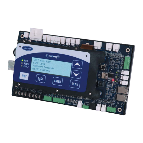
a48--- 9373 Fig. 2 - - SystemVut - - Main Menu Structures Accessory Navigatort Display SystemVu Interface Operation Units are shipped from the factory with the SystemVu interface The accessory hand-held Navigator display can be used with the FIOP, located in the main control box. (See Fig. 1.) In addition, the 48/50LC units. -
Page 5: System Pilott And Touch Pilott Devices
3Vt zoning system, linkage compatible air source, flashes. Use the arrow keys to change the value of state of an item universal controller, and all other devices operating on the Carrier and press the ENTER key to accept it. Press the ESCAPE key and communicating network. -
Page 6: Start-Up
Compressor Rotation CAUTION UNIT DAMAGE HAZARD Failure to follow this caution may result in unit damage. Improper wiring will cause compressor stoppage and alarm. Correct wiring by switching leads as indicated below. NAVIGATE/ MODIFY/ On 3-phase units, it is important to be certain the compressors are EXIT SELECT rotating in the proper direction. -
Page 7: Condenser Fans And Motors
return-air filters. Determine the filter change run time (DIRTY IMPORTANT: The IDF Maximum Fan Speed (MAXIMUM FILTER TIME) to be set in the quick setup configurations menu. IDF SPEED) RPM must not produce a supply CFM that is Outdoor- -Air Inlet Screens lower than the minimum CFM allowed in the product data for heating and cooling. -
Page 8: Gas Heat (48Lc)
INDOOR BLOWER ACCESS PANELS CONTROL BOX ACCESS PANEL FILTER ACCESS PANEL INDOOR COIL GAS SECTION ACCESS PANEL ACCESS PANEL UNIT FRONT UNIT BACK C14322 Fig. 7 - - 48/50LC Size 08- -12 Units, Panel and Filter Locations (48LC*09 Unit Shown) INDOOR BLOWER ACCESS PANEL OUTDOOR AIR... -
Page 9: Controls Quick Set- -Up
Table 3 – Quick Setup Menu Items MANUAL GAS SHUT OFF VALVE (FIELD SUPPLIED) SystemVu™ Display Expanded Name Range Default QUICK SETUP QUICK SETUP CONFIG CONFIG MENU SUPPLY TIME Clock Hour and Minute HH:MM DATE Current Date MM/DD/YYYY SUPPLY GAS PRESSURE TAP STARTUP DELAY Unit Startup Delay... -
Page 10: Ccn Communication
CCN Communication Outdoor Enthalpy When an Outdoor Enthalpy sensor is field- -installed, the unit must First configure the building protocol SETTINGS NETWORK SETTINGS UNIT be configured for it by setting SETTINGS BAS PROTOCOL to CCN (default is 0 = NONE). CONFIGURATIONS ... -
Page 11: Service Test
SERVICE TEST Heating Test The HEAT submenu is used to change output status for the The Service Test function can be used to verify proper operation of individual heat stages, gas or electric. The COOL service test compressors, heating stages, indoor fan, outdoor... -
Page 12: Automatic Test
Automatic Test must be 0 (Tstat) to recognize the below inputs. Terminal R is the 24- -VAC source for the following: The AUTOMATIC TEST submenu is used to execute all the Y1 = first stage cooling applicable tests to the system automatically. These include independent component, cooling, heating, and a system one. -
Page 13: Unit Configuration
PASSWORD ENABLE? STD BARO PRESSURE This variable enables or disables the use of a user password. The This configuration is used to specify the job location’s standard password is used to restrict use of the control to change configurations. barometer pressure reading. This will feed the BAROMETRIC PRESS when a network is not writing to it. -
Page 14: Demand Determination
cool and heat setpoints (EFF COOL SETPOINT and EFF HEAT overall demand of the unit. Table 8 shows the possible system SETPOINT). However, to minimize unnecessary cool to heat and demands with their priority level and summary description. heat to cool changes, there is a 10 minute delay after the last stage Thermostat Demand turns off before the control will switch modes. -
Page 15: Occupancy Determination
Table 10 – Thermostat Heating System Demands In general the system demand will increase based on the demand compared to the demand switch states in Fig. 11. The demand Thermostat Input THERMOSTAT TYPE cannot increase until Time guard 1 (DEMAND TIMEGUARD1) CONV 2C2H DIGI 2C2H expires. -
Page 16: Indoor Fan Operation
While using the programmed schedule, occupancy can be humidity set point deadband (SPRH DEADBAND). This would temporarily switched from unoccupied to occupied by pressing the come from the space humidity sensor, or building network. override button for approximately 3 seconds on the T- -55, T- -56, or Indoor Fan Operation T- -59 space temperature sensor. -
Page 17: Cooling Operation
Indoor (Supply) Fan Maximum Speed Cooling Mode Control (MAXIMUM IDF SPEED) The cooling HVAC mode (OPERATING MODE) has 9 different Max speed is the highest fan speed allowed. This is typically 100% operating sub modes (SUBMODE): ECON FREE COOLING, when pulleys are set to deliver design CFM to the space per job UNOCC. - Page 18 Traditional Thermostat Control lockout will be active (LOW COOL LOCKOUT) preventing compressor A1 from running by itself. Any time the outdoor ambient Stage timers and Supply air trend do not apply when determining the falls below the medium cooling minimum outdoor temperature (MED request for stages.
-
Page 19: Optional Humidi- -Mizer
(closed) TEMP) is default to 66 degrees and should not be changed unless Dehum/Mech High Cooling (closed) directed by authorized Carrier Personnel. Optional Humidi- -MiZer Dehumidification System High Dehum (open) Units with the factory- -installed Humidi- -MiZer system option are... - Page 20 Dehumidification (Hot Gas Reheat Mode) demand, the unit will operate in Dehumidification mode (Hot Gas Reheat). When there is both cooling demand and dehumidification This mode provides maximum latent cooling with little to no demand, the unit will operate in Dehum/Mech Cooling mode sensible capacity.
- Page 21 INDOOR SUPPLY VALVE CONDENSER COIL HUMIDI-MIZER COIL VALVE OUTDOOR AIR EXPANSION VALVE VALVE (TXV) COMPRESSOR EVAPORATOR COIL = CLOSED VALVE = OPEN VALVE INDOOR RETURN C14122 Fig. 15 - - Subcooling Mode – Humidi- -MiZer System 48/50LC 04- -06 INDOOR SUPPLY VALVE 3-WAY VALVE...
-
Page 22: Indoor Fan Based Dehumidification
INDOOR SUPPLY VALVE 3-WAY VALVE CONDENSER COIL HUMIDI-MIZER COIL OUTDOOR AIR EXPANSION VALVE (TXV) COMPRESSOR EVAPORATOR COIL = CLOSED VALVE = OPEN VALVE INDOOR RETURN = 3-WAY VALVE C14116 Fig. 18 - - Hot Gas Reheat Mode – Humidi- -MiZer System 48/50LC 07- -26 Reheat Mode Diagnostic Help configuration, SETTINGS UNIT CONFIGURATIONS... - Page 23 at any given time. All types of heating are still performed under the (DEMAND). A “LOW HEAT” will only allow one requested stage general heating function, and the expanded text is for user and “HIGH HEAT” 2 stages. The requested stages will be reduced reference only.
-
Page 24: Supply Air Tempering
(HEAT 2 RELAY), power is supplied to the second stage of the main 1. Activate test mode to control the fan and dampers to gas valve. If both stage 1 and stage 2 of the gas valve close, gas will achieve the correct numbers. - Page 25 Key : Minimum Position Curve IAQ Minimum Position Curve (AQP_SPD3, AQP_POS3) IAQ Purge Position Curve Econo Max Position (DAMPMAX) (AQP_SPD2, AQP_POS2) (AQP_SPD1, AQP-POS1) IAQPMAX (MP_SPD3, MP_POS3) (AQ_SPD3, (MP_SPD2, AQ_POS3) MP_POS2) (MP_SPD1, MP_POS1) (AQ_SPD2, AQ_POS2) MINP_ MAX (AQ_SPD1, AQ_POS1) IAQMINP Maximum Speed (SPEEDMAX) Indoor Fan Speed C14326...
-
Page 26: Power Exhaust
Unoccupied Free Cooling When a power exhaust 1 relay channel is configured, the control will create a PE1 curve, example shown in Fig. 20. This curve is The unoccupied free cooling algorithm attempts to maintain the created by applying the difference of the power exhaust stage 1 at building space half way between the Occupied Cool Set Point (OCC maximum fan speed (PE1 POS @ MAX SPD) and the Economizer COOL SETPOINT) and Occupied Heat Set Point (OCC HEAT... -
Page 27: Pre- -Occupancy Purge
IAQ (Analog Input) position will be zero. The actual damper position may exceed the economizer Min Position in Effect (EFFECTIVE MIN POS) to When IAQ assigned channel (IAQ SENSOR CHAN) is set for an provide economizer cooling. analog input that input channel will be mapped to the Indoor Air Quality (IAQ LEVEL). -
Page 28: Linkage
CCN tool. If three strikes occur before the circuit has an opportunity to show that Carrier Comfort Network (CCN) Operation it can function properly, the circuit will strike out, causing the The SystemVu controller can be configured to connect to a CCN shutdown fault for that particular circuit. -
Page 29: Complete Unit Stoppage
Complete Unit Stoppage the unit. This will automatically clear when the fuse temperature gets back in range. The cause of this fault is usually a switch input There are several conditions that can cause a complete unit has a wiring error (short) or the switch pulled too much current. stoppage, including: Discrete input number 2, Fire Shutdown input, and the IGC fan... - Page 30 shorted or open thermistor caused by a wiring error, or a loose Alert A133 – CIR.A SDP SENSOR RANGE connection. This alert occurs when the pressure is outside the range 14.5 to 667 Alert A102 – FST OPEN SENSOR psig. A circuit cannot run when this alert is active. The cause of the alert is usually a faulty transducer, faulty 5- -v power supply, or a This alert occurs when the fan supply temperature sensor reads as loose connection.
- Page 31 Alert A168 - - SPACE RELATIVE HUMIDITY OPEN SENSOR inspected. Rest the time with the RESET FILTER TIME point is located under RUN STATUS GENERAL or INPUTS This alert occurs when the SPRH input is 0 mA and the sensor is GENERAL INPUTS.
- Page 32 temperature coupled with dirty outdoor coil, plugged filter drier, or Fault F322 – C.A2 DOWN DUE TO FAIL ODF speeds being set too low. This fault occurs when compressor A2 has 3 strikes. Investigate the Alert A315 – CIR.A LOW DISCHARGE alerts that caused the strikes to occur, and correct or test as needed.
- Page 33 communication connection, noise on the LEN bus, wiring error, or a Fault F614 – IDF VFD MOTOR OVER TEMP configuration error. Verify VFD configurations are set per the latest See fault F601 literature. Fault F615 – IDF VFD OVERLOAD Fault F601 – IDF VFD UNEXPECTED See fault F601 This fault occurs when the indoor fan VFD informs the SystemVu Fault F616 –...
- Page 34 Table 13 – SystemVut Controller Alarm Codes ACTION TAKEN BY RESET FAULT OR ALERT PROBABLE CAUSE CONTROL METHOD F010--- MBB LOW VOLTAGE Unit Shutdown Automatic Brownout condition, low supply voltage, supply power missing a phase. F011--- MBB REFERENCE VOLTAGE Unit Shutdown Automatic MBB failure or supply voltage low A012--- MBB ZERO CROSSING...
- Page 35 Table 13 — SystemVut Controller Alarm Codes (cont) ACTION TAKEN BY RESET FAULT OR ALERT PROBABLE CAUSE CONTROL METHOD A210--- GENERAL STATUS Alert Generated Automatic General Switch activation or wrong configuration F211--- GENERAL STATUS Unit Shutdown Automatic General Switch activation or wrong configuration F310--- CIRA DOWN DUE TO FAIL Shutdown Circuit A Manual...
-
Page 36: Control Module Communication
Control Module Communication Red LED Navigatort display. The MBB J15 connector provides a LEN interface to the indoor fan VFD. Proper operation of the MBB control board can be visually Yellow LED checked by looking at the red status LED. When operating correctly, the red status LED should blink at a rate of once every 2 The MBB has one yellow LED which is used to indicate Building seconds. -
Page 37: Cooling Troubleshooting
Cooling Troubleshooting Use the SystemVut Display or a CCN device to view the cooling If alarms conditions are corrected and cleared, operation of the status display and the cooling diagnostic display (see Appendices) compressors and fans may be verified by using the Service Test for information on the cooling operation. -
Page 38: Humidi- -Mizer System Troubleshooting
Humidi- -MiZer System Troubleshooting Use the SystemVut control display or a CCN device to view the cooling status display and the cooling diagnostic display. See Optional Humidi- -MiZer Dehumidification System starting on page 19 for information on the cooling operation and the related Humidi- -MiZer system operation. - Page 39 Table 16 – Humidi- -MiZer System Service Analysis PROBLEM CAUSE REMEDY Subcooling Reheat Mode General cooling mode problem. See Cooling Service Analysis (Table 15). Will Not Activate. No dehumidification demand. See No Dehumidification Demand, below. IOB operation. See IOB Operation, below. Circuit LDV valve problem.
-
Page 40: Economizer Troubleshooting
Identify the obstruction and safely remove. Power Loss. Economizer is Not at Configured Unit is operating under free cooling or a force is Economizer is operating correctly. Minimum Position applied to the commanded position. LEGEND Carrier Comfort Network Indoor Air Quality... -
Page 41: Heating Troubleshooting
Heating Troubleshooting Gas Heat (48LC Units) Use the unit SystemVut Display or a CCN device to view the heating status display and the heating diagnostic display (see See Table 18 for general gas heating service analysis. See Fig. 24 Appendices) for information on the heating operation. Check the for service analysis of the IGC board logic. - Page 42 24 VOLTS DEFECTIVE 1 FLASH - INDOOR FAN DELAY FLASHING BETWEEN LED is IGC BOARD MODIFIED (HEATING) F1 AND C 2 FLASHES - OPENING OF LIMIT SWITCH 1. BLOWN 5 AMP FUSE 3 FLASHES - FLAME SENSOR 2. DEFECTIVE 24V TRANS. INDICATES FLAME WITH 3.
- Page 43 Table 19 – IGC Board LED Alarm Codes ACTION TAKEN BY FLASH DESCRIPTION RESET METHOD PROBABLE CAUSE CONTROL CODE Normal Operation — — — Hardware Failure No gas heating. Loss of power to the IGC. Check 5 amp fuse on IGC, —...
-
Page 44: Phase Protection
Phase Protection Thermistor/Temperature Sensor Check A digital volt-ohmmeter is required to perform this check. The phase loss protection option will monitor the three-phase electrical system to provide phase reversal and phase loss protection. Connect the digital volt- -ohmmeter across the appropriate thermistor terminals at the J8 connector on the Main Base Board Phase Reversal Protection (see Major System Components section). - Page 45 Table 21 – Temperature (_F) vs Resistance/Voltage Drop Values for OAT, RAT, SAT, and SPT Thermistors (10K at 25_C Type II Resistors) TEMP RESISTANCE VOLTAGE TEMP RESISTANCE VOLTAGE TEMP RESISTANCE VOLTAGE (Ohms) DROP (V) (Ohms) DROP (V) (Ohms) DROP (V) –25 196,453 4.758...
- Page 46 Table 22 – Pressure (psig) vs. Voltage Drop Values for Suction Pressure Transducers PRESSURE VOLTAGE PRESSURE VOLTAGE PRESSURE VOLTAGE PRESSURE VOLTAGE (psig) DROP (V) (psig) DROP (V) (psig) DROP (V) (psig) DROP (V) 0.465 1.135 1.804 2.474 0.485 1.154 1.824 2.493 0.505 1.174...
- Page 47 Table 23 – Discharge Pressure Transducer (psig) vs. Voltage PRESSURE VOLTAGE PRESSURE VOLTAGE PRESSURE VOLTAGE PRESSURE VOLTAGE (psig) DROP (V) (psig) DROP (V) (psig) DROP (V) (psig) DROP (V) 0.500 0.993 1.490 1.987 14.5 0.509 1.000 1.496 1.993 0.515 1.006 1.502 1.999 0.521...
- Page 48 Table 23 - - Discharge Pressure Transducer (psig) vs. Voltage (cont) PRESSURE VOLTAGE PRESSURE VOLTAGE PRESSURE VOLTAGE PRESSURE VOLTAGE (psig) DROP (V) (psig) DROP (V) (psig) DROP (V) (psig) DROP (V) 2.483 2.992 3.501 4.010 2.489 2.998 3.507 4.016 2.495 3.004 3.513 4.022...
-
Page 49: Major System Components
MAJOR SYSTEM COMPONENTS monitors all operations of the rooftop. The control system is composed of several main control components and available General factory-installed options or field-installed accessories as listed in The 48/50LC single package rooftop units are available with the sections below. - Page 50 C14329B Fig. 27 - - 48LC 08- -12 SystemVut Control Schematic...
- Page 51 a50--- 9603 Fig. 28 - - 50LC 14- -26 SystemVut Control Schematic...
- Page 52 a48--- 9942 Fig. 29 - - 50LC 04- -06 SystemVut Power Schematic...
- Page 53 a48--- 9943 Fig. 30 - - 48LC 08- -12 SystemVut Power Schematic...
- Page 54 a48--- 9944 Fig. 31 - - 48/50LC 14- -26 SystemVut Power Schematic...
-
Page 55: Main Base Board (Mbb)
Main Base Board (MBB) See Fig. 32 and Table 24. The majority of the I/O is connected to the MBB which executes the controls operation of the unit from the software that is loaded onto it. C150161 Fig. 32 - - Main Base Board (MBB) - Page 56 Table 24 – Main Base Board (MBB) Connections CONNECTION PIN DISPLAY NAME SENSOR LOCATION I/O TYPE POINT NAME NUMBER INPUTS Input power from TRAN2 Control Box 24 VAC J2, 1 & 8 COFS Dain Pan 24 VAC COFS J4, 1--- 4 FIRE SHUTDOWN Supply/Return/Space Switch input...
-
Page 57: Input- -Output Board (Iob)
Input- -Output Board (IOB) PD4-AUX1 32GB 500 322 EE CEPL130487-01 STATUS CH14 CH13 a50--- 9608 Fig. 33 - - Input- -Output Board (IOB) Table 25 – Input- -Output Board (IOB) Connections CONNECTION DISPLAY NAME POINT DESCRIPTION SENSOR LOCATION TYPE OF I/O PIN NUMBER INPUTS HUMIDISTAT... -
Page 58: Integrated Gas Control (Igc) Board
Integrated Gas Control (IGC) Board The IGC is provided on gas heat units. The IGC controls the direct spark ignition system and monitors the rollout switch, limit switch, and flue gas pressure switch. RED LED-STATUS C07028 Fig. 34 - - Integrated Gas Control (IGC) Board Table 26 –... -
Page 59: Protective Devices
Protective Devices Condensate Overflow Switch (COFS) A separate factory installed device can detect a full drain pan. This Compressor Protection device consists of a pan sensor to detect the water level and a relay Overcurrent control switch to read the sensor. The control switch is located in Each compressor has internal line break motor protection. - Page 60 TB1-T55 TO MAIN BASE BOARD SENSOR 1 SENSOR 2 SENSOR 3 SENSOR 4 SPACE TEMPERATURE AVERAGING --4 T-55 SENSOR APPLICATION TB1-T55 TO MAIN BASE BOARD SENSOR 1 SENSOR 2 SENSOR 3 LEGEND -- Terminal Block ______ -- Factory Wiring _ _ _ _ -- Field Wiring SENSOR 4 SENSOR 5...
-
Page 61: Variable Frequency Drive (Vfd)
Failure to follow this caution may result in damage to the unit or in degradation of unit performance. Do not run the Carrier Assistant through the VFD keypad. This will cause parameters to change value that are not desired on these applications. - Page 62 Table 28 – LC 04- -06 VFD Parameters Configured by Factory or VFD Keypad Parameter Group Parameter Title ABB Parameter HVAC Default CARRIER Options COMM PROT SEL 9802 NOT SEL LEN (6) EFB PROTOCOL ID 5301 0000 hex 0601 hex...
- Page 63 Table 32 – LC 04- -06 VFD Motor Default Configurations Motor Current Nominal Motor Nominal EQUIPMENT MODEL NUMBER (EQ_MOD) Motor Voltage VFD Max Amps (Must--- Hold Horse Power Speed Amps) Position 1,2 Position 7,8 Position 10 Position 12 MOTPWRHP MOTVOLT MOTCUR MOTNOMSP VFD1MAXA...
- Page 64 3. Overriding the control panel display with the display of a To reset a fault indicated by a flashing red LED, turn off the power fault code for 5 minutes. To reset a fault indicated by a red LED (not flashing), press RESET from the control panel or turn off the 4.
-
Page 65: Lc 07- -26 Variable Frequency Drive (Danfoss Vfd)
The VFD motor parameters shown in Table 39 should never be requirements for each motor selection and all wiring connections changed in the field unless authorized by Carrier Corporation. are completed by the factory; no field adjustments are necessary. Damage could occur to the motor or unit if these are set to The VFD used has soft start capabilities to slowly ramp up the anything besides what is shown in the table. - Page 66 Table 35 – LC 07- -26 VFD Parameters Configured by Factory or VFD Keypad Parameter Group Parameter Title Danfoss Parameter VFD Default CARRIER Reset Functions Service Code 14--- 29 6333 6222 PROTOCOL 8--- 30 (0) FC (20) LEN ADDRESS 8--- 31...
- Page 67 Table 38 – LC 07- -26 VFD Status Parameters Available Through SystemVut Controller Parameter Group Parameter Title Danfoss Parameter Units SystemVu Point SystemVu Display Item Running Hours 15--- 01 RUNHOURS IDF VFD RUN HOURS Operating Data kWh Counter 15--- 02 KWHCNTR IDF VFD KW HOURS Reference [%]...
- Page 68 Table 39 - - LC 07- -26 VFD Motor Default Configurations - - Vertical Airflow Units (cont) Motor Current Nominal Motor Nominal EQUIPMENT MODEL NUMBER (EQ_MOD) Motor Voltage VFD Max Amps (Must--- Hold Horse Power Speed Amps) Position 1,2 Position 7,8 Position 10 Position 12 MOTPWRHP...
- Page 69 Table 39 - - LC 07- -26 VFD Motor Default Configurations - - Vertical Airflow Units (cont) Motor Current Nominal Motor Nominal EQUIPMENT MODEL NUMBER (EQ_MOD) Motor Voltage VFD Max Amps (Must--- Hold Horse Power Speed Amps) Position 1,2 Position 7,8 Position 10 Position 12 MOTPWRHP...
- Page 70 Table 39 - - LC 07- -26 VFD Motor Default Configurations - - Vertical Airflow Units (cont) Motor Current Nominal Motor Nominal EQUIPMENT MODEL NUMBER (EQ_MOD) Motor Voltage VFD Max Amps (Must--- Hold Horse Power Speed Amps) Position 1,2 Position 7,8 Position 10 Position 12 MOTPWRHP...
- Page 71 Table 40 – LC 07- -26 VFD Motor Default Configurations - - Horizontal Airflow Units Motor Current Nominal Motor Nominal EQUIPMENT MODEL NUMBER (EQ_MOD) Motor Voltage VFD Max Amps (Must--- Hold Horse Power Speed Amps) Position 1,2 Position 7,8 Position 10 Position 12 MOTPWRHP MOTVOLT...
- Page 72 Table 40 - - LC 07- -26 VFD Motor Default Configurations - - Horizontal Airflow Units (cont) Motor Current Nominal Motor Nominal EQUIPMENT MODEL NUMBER (EQ_MOD) Motor Voltage VFD Max Amps (Must--- Hold Horse Power Speed Amps) Position 1,2 Position 7,8 Position 10 Position 12 MOTPWRHP...
- Page 73 F623---IDF VFD Control Voltage CONTROL 24 V DC may be overloaded. Fault VOLTAGE F624---IDF VFD Control voltage low. Please contact your local Carrier VDD1 Supply Low SUPPLY VDD representative. F601---IDF VFD A605--- IDF VFD THERMAL Motor thermistor Thermistor or thermistor connection is disconnected. See...
-
Page 74: Carrier Comfort Network R (Ccn) Interface
4. The RJ14 CCN connector on CIB can also be used, but is required. See Table below for acceptable wiring. only intended for temporary connection (for example, a laptop computer running Carrier network software). MANUFACTURER PART NO. 5. Restore power to unit. - Page 75 UNIT BUILDING SUPERVISOR NETWORK ROOFTOP ROOFTOP OPTIONS UNIT UNIT LEGEND ® CCN -- Carrier Comfort Network ComfortLink Controls DAV -- Digital Air Volume HEATING/COOLING UNITS HVAC -- Heating, Ventilation, and Air Conditoning REMOTE AUTODIAL TCU -- Terminal Control Unit CCN SITE...
-
Page 76: Appendix A: Systemvut Controller Display
APPENDIX A: SystemVut Controller Display Run Status Main Menu Layout Display Text Expanded Text Values Units Write Status Point SHUTDOWN UNIT? Local Unit Shutdown Req. Yes/No Command RUN STATUS Run Status Menu MODE Mode Status Menu MODE Operating Mode see Appendix B MODETEXT SUB--- MODE Operating Sub--- Mode... - Page 77 APPENDIX A: SystemVut Controller Display Run Status Main Menu Layout (cont) Display Text Expanded Text Values Units Write Status Point COOL (cont) Cooling Status Menu DEHUM DEHUM OK TO DEHUM Ok to Dehumidify? Yes/Nolocked out OKTODHUM OD TO FAN BASE DH Ok to fan based dehum Yes/No OKTOFBD...
- Page 78 APPENDIX A: SystemVut Controller Display Run Status Main Menu Layout (cont) Display Text Expanded Text Range Units Default Point OCCUPANCY OCCUPANCY DATA OCCUPIED NOW Currently Occupied Yes/No Forcible OCCUPIED MINS UNTIL OCC Mins until next occupied xxxxx MINTILOC ACTIVE OCC CTRL Active Occupancy control 0=24/7 OCC, OCC_CTRL...
- Page 79 APPENDIX A: SystemVut Controller Display Settings Main Menu Layout (cont) Display Text Expanded Text Range Units Default Point CLOCK (cont) Clock Adjustment Menu DST START MONTH DST Start Month 1=JANUARY, STARTM 2=FEBRUARY, 3=MARCH, 4=APRIL, 5=MAY, 6=JUNE, 7=JULY, 8=AUGUST, 9=SEPTEMBER, 10=OCTOBER, 11=NOVEBER, 12=DECEMBER DST START WEEK...
- Page 80 APPENDIX A: SystemVut Controller Display Settings Main Menu Layout (cont) Display Text Expanded Text Range Units Default Point UNIT CONFIGURATIONS (cont) Unit Configurations Menu SWITCH INPUTS CONFIGS DI Config Menu FIRE SHUTDOWN SW Fire Shutdown Switch 0=NORM OPEN, 2: no FIOP FIRE_CFG 1=NORM CLSD, 0: FIOP...
- Page 81 APPENDIX A: SystemVut Controller Display Settings Main Menu Layout (cont) Display Text Expanded Text Range Units Default Point ANALOG INPUT CONFIGS (cont) Analog Inputs Configuration Menu OAQ SENSOR CHAN OAQ Assigned Channel 0=None, 0=None OAQ_CHAN 1=MBB AI06, 2=MBB AI07, 3=MBB AI08 OAQ PPM @ 4MA OAQ Sensor Value at 4mA 0 to 5000...
- Page 82 APPENDIX A: SystemVut Controller Display Settings Main Menu Layout (cont) Display Text Expanded Text Range Units Default Point COOLING (cont) Cooling Configurations Menu LDVA ENABLE Liquid Divert Valve CirA Yes/No enum No for all except LDVA_EN Humidimizer units sizes 07--- 26 CHARGE DIAGNOSTICS Refrigerant Charge Diagnostic Config Menu LOW CHARGE LEVEL...
- Page 83 APPENDIX A: SystemVut Controller Display Settings Main Menu Layout (cont) Display Text Expanded Text Range Units Default Point ODF SETTINGS (cont) Outdoor Fans Configurations Menu ODF MBIAS 3 ODF Map Bias Term 3 --- 200 to 200.00 20.93 (sizes 04--- 06) ODFBIAS3 0 (sizes 07, 14--- 20) 65.29 (sizes 08--- 12)
- Page 84 APPENDIX A: SystemVut Controller Display Settings Main Menu Layout (cont) Display Text Expanded Text Range Units Default Point INDOOR FAN (cont) Indoor Fan Configurations Menu IDF VFD NOM. FREQ IDF VFD Nom. Motor Freq 20 to 400 MOTRFEQ IDF VFD NOM. AMPS IDF VFD Nom.
- Page 85 APPENDIX A: SystemVut Controller Display Settings Main Menu Layout (cont) Display Text Expanded Text Range Units Default Point ECONOMIZER (cont) Economizer Configurations Menu MDD--- MIN MOVE T24Econ Min Move for SAT 10 to 20 T24ECSTS MDD--- SAT DB Damper SAT deadband 0 to 20.0 °...
- Page 86 APPENDIX A: SystemVut Controller Display Settings Main Menu Layout (cont) Display Text Expanded Text Range Units Default Point NEW HARDWARE (cont) Quick Menu for New Hardware OACFM SENS CHANNEL OACFM Assigned Channel 0=None, 0=None OCFMCHAN 1=MBB AI06, 2=MBB AI07, 3=MBB AI08, 4=SIOB Ai10 FIRE SHUTDOWN SW Fire Shutdown Switch...
- Page 87 APPENDIX A: SystemVut Controller Display Settings Main Menu Layout (cont) Display Text Expanded Text Range Units Default Point NETWORK SETTINGS (cont) Building Network Configurations Menu DEVICE IAQ BACnet device for IAQ 0 to 4194303 1610100 DEVIAQ OBJECT ID IAQ Object instance for IAQ 0 to 9999 1009 OBJIAQ...
- Page 88 APPENDIX A: SystemVut Controller Display Settings Main Menu Layout (cont) Display Text Expanded Text Range Units Default Point QUICK SETUP CONFIG (cont) Building Network Configurations Menu HEATING STAGE QTY Number of Heating Stages 0 to 2 2 (all except below): NUMHSTGS 0 (50 series without FIOP heat),...
- Page 89 APPENDIX A: SystemVut Controller Display Service Main Menu Layout Display Text Expanded Text Values Units Write Status Point SERVICE Service Menu UNIT TESTS Unit Tests Menu TEST MODE Service Test Mode Enable On/Off Command SERVICE TEST Service Test Menu INDEPENDENTS INDEPENDENT TEST MENU ECON POS TEST Economizer Position Test...
- Page 90 APPENDIX A: SystemVut Controller Display Service Main Menu Layout (cont) Display Text Expanded Text Values Units Write Status Point RUN HOURS & CYCLES Run Hours & Cycles Menu RUN HOURS DATA MENU Run hours menu COMP A1 RUN HOURS Compressor A1 Run Hours xxxxxx.x hours HR_A1...
- Page 91 APPENDIX A: SystemVut Controller Display Service Main Menu Layout (cont) Display Text Expanded Text Values Units Write Status Point RESET COUNTS MENU (cont) Reset Counts menu ODF3 OUT RESETS ODF Signal3 Resets Count xxxxxx RS_ODF3 PE1 RESET QTY P .Exhaust 1 Resets Count xxxxxx RS_PE_1 PE2 RESET QTY...
- Page 92 APPENDIX A: SystemVut Controller Display Service Main Menu Layout (cont) Display Text Expanded Text Values Units Write Status Point HARDWARE Hardware Information Menu HARDWARE INPUTS Hardware inputs menu OAT SENSOR VALUE Outdoor Air Temp Sensor xxx.x ° F OAT_LOC RAT SENSOR VALUE Return Air Temp Sensor xxx.x °...
- Page 93 APPENDIX A: SystemVut Controller Display Service Main Menu Layout (cont) Display Text Expanded Text Values Units Write Status Point HARDWARE INPUTS (cont) Hardware inputs menu RELAY 06 FUNCTION Assigned Rly 06 Function 0=None, MBBRY06F 1=ALM Relay, 2=PE1, 3=PE2 RELAY 11 FUNCTION Assigned Rly 11 Function 0=None, MBBRY11F...
- Page 94 APPENDIX A: SystemVut Controller Display Inputs Main Menu Layout Display Text Expanded Text Values Units Write Status Point TEMPERATURES (cont) Temperatures Menu CIR.A DIS. TEMP Cir.A Sat.Discharge Temp xxx.x ° F SDT_A FAN SUPPLY TEMP Fan Supply Air Temp xxx.x °...
- Page 95 APPENDIX A: SystemVut Controller Display Inputs Main Menu Layout (cont) Display Text Expanded Text Values Units Write Status Point GENERAL INPUTS (cont) General Inputs Menu VFD FAULT DETAIL IDF VFD Fault Detail 0=NONE, SVFDFLT 1=PWR CARD, 2=EARTH FLT, 3=CTRL WORD, 4=OVER CURR, 5=OVER TEMP , 6=OVERLOAD,...
- Page 96 APPENDIX A: SystemVut Controller Display Outputs Main Menu Layout Display Text Expanded Text Values Units Write Status Point OUTPUTS Outputs Menu GENERAL OUTPUTS General Outputs Menu IDF SPEED OUTPUT Commanded IDF Speed 0 to 100 FANSPEED ECON CMD POSITION Econo Commanded Position 0 to 100 Forcible DAMPCMD...
-
Page 97: Appendix B: Systemvu Controller Text Point Reference
APPENDIX B: SystemVut Controller Text Point Reference SystemVu Display Name = MODE SystemVu Display Name = VENT MODE SystemVu Text point = MODETEXT SystemVu Text point = VENTTEXT SystemVu Numeric point = SYS_MODE SystemVu Numeric point = VENTSTAT MODETEXT SYS_MODE VENTTEXT VENTSTAT SUPPLY FAN OFF... -
Page 98: Appendix C: Navigatort Display
APPENDIX C: Navigatort Display MODE - - RUN STATUS ITEM EXPANSION RANGE UNIT WRITE STATUS POINT RUN STATUS VIEW Auto View of Run Status MODE Operating Mode see Appendix B MODETEXT SUBM Operating Sub--- Mode see Appendix B SUBMTEXT S.DMD System Demand see Appendix B SYS_DMDT... - Page 99 APPENDIX C: Navigatort Display MODE - - RUN STATUS (cont) ITEM EXPANSION RANGE UNIT WRITE STATUS POINT VENT Ventilation Status Menu VENT Ventilation Status see Appendix B VENTTEXT EC.MP Min Position in Effect MIN_POS EC.AP Econo Actual Position DAMPPOS C.SPD Commanded IDF Speed FANSPEED Currently Occupied...
- Page 100 APPENDIX C: Navigatort Display MODE - - RUN STATUS (cont) ITEM EXPANSION RANGE UNIT WRITE STATUS POINT Run Hours & Cycles Menu Run hours menu Compressor A1 Run Hours xxxxxx.x hours HR_A1 Compressor A2 Run Hours xxxxxx.x hours HR_A2 CMP A1 Loader Run Hours xxxxxx.x hours HR_ALDR...
- Page 101 APPENDIX C: Navigatort Display MODE - - RUN STATUS (cont) ITEM EXPANSION RANGE UNIT WRITE STATUS POINT RUN (CONT) Run Hours & Cycles Menu Power On Reset Hist Menu POR0 Power Reset Event 00 mm/dd/yy, POWRES00 hh:mm:ss POR1 Power Reset Event 01 mm/dd/yy, POWRES01 hh:mm:ss...
- Page 102 APPENDIX C: Navigatort Display MODE - - RUN STATUS (cont) ITEM EXPANSION RANGE UNIT WRITE STATUS POINT A.IO (cont) Assigned I/O Channels DI14 Assigned DI14 Function 0=None, MBBDI14F 1=COFS, 2=REMOCC, 3=REMOFF, 4=FILTER, 5=ENTHALPY, 6=GEN STAT, 7=HUMIDISTAT SD04 Assigned S--- DI01 Function 0=None, SIODI01F 1=COFS,...
- Page 103 APPENDIX C: Navigatort Display MODE - - TEMPERATURES WRITE ITEM EXPANSION RANGE UNIT POINT STATUS TEMPERATURES Supply Air Temperature xxx.x ° F Outdoor Air Temperature xxx.x ° F Return Air Temperature xxx.x ° F Space Temperature xxx.x ° F SPACE_T SPTO Space Temperature Offset xx.x...
- Page 104 APPENDIX C: Navigatort Display MODE - - INPUTS WRITE ITEM EXPANSION RANGE UNIT POINT STATUS INPUTS STAT Thermostat Inputs menu Thermostat G Input On/Off Thermostat Y1 Input On/Off Thermostat Y2 Input On/Off Thermostat Y3 Input On/Off Thermostat W1 Input On/Off Thermostat W2 Input On/Off Switch Inputs Menu...
- Page 105 APPENDIX C: Navigatort Display MODE - - INPUTS WRITE ITEM EXPANSION RANGE UNIT POINT STATUS NET (cont) Network Menu ZSSI ZS Sensor Information ZS.ZT Zone Sensor Temp Out --- 40 to 245 ° F ZSZT ZS.RH Zone Sensor Humidity Out 0 to 1 °...
- Page 106 APPENDIX C: Navigatort Display MODE - - INPUTS (cont) WRITE ITEM EXPANSION RANGE UNIT POINT STATUS DATA User Measured Data Menu Supply Voltage Leg 1 0 to 700 volt L1VOLTS Supply Voltage Leg 2 0 to 700 volt L2VOLTS Supply Voltage Leg 3 0 to 700 volt L3VOLTS...
- Page 107 APPENDIX C: Navigatort Display MODE - - CONFIGURATIONS ITEM EXPANSION RANGE UNIT DEFAULT POINT CONFIGURATION General Unit Config Menu S.DLY Unit Startup Delay 10 to 600 STARTDLY U.CTL Unit Control Type 0=TSTAT, 0=TSTAT CTRLTYPE 1=SPACE SEN, 2=RAT SEN T.CTL Thermostat Hardware Type 0=CONV 2C2H, 2=CONV 3C2H STATTYPE...
- Page 108 APPENDIX C: Navigatort Display MODE - - CONFIGURATIONS (cont) ITEM EXPANSION RANGE UNIT DEFAULT POINT DIS (count) DI Config Menu GN.SW General Status Sw Type 0=NORM OPEN, 0=NORM OPEN GENS_CFG 1=NORM CLSD GEN.F General Status shutdown? Yes/No GENFATAL ENT.C Enthalpy Sw Channel 0=None, 0=None ENTHCHAN...
- Page 109 APPENDIX C: Navigatort Display MODE - - CONFIGURATIONS (cont) ITEM EXPANSION RANGE UNIT DEFAULT POINT COOL (cont) Cooling Configs Menu L.AMB Low Ambient Configs Menu CA.LO Circuit A Lockout Temp --- 20 to 75 ° F 0: no Economizer FIOP OATLCMPA 40: Economizer FIOP LA.T...
- Page 110 APPENDIX C: Navigatort Display MODE - - CONFIGURATIONS (cont) ITEM EXPANSION RANGE UNIT DEFAULT POINT ODF (cont) Outdoor Fans Config Menu ODF Map Bias Term 3 --- 200 to 200 0 (sizes 07, 14--- 20) ODFBIAS3 65.29 (sizes 08--- 12) 114.74 (sizes 24--- 26) ODF Fan Switch Point 1 --- 100 to 100...
- Page 111 APPENDIX C: Navigatort Display MODE - - CONFIGURATIONS (cont) ITEM EXPANSION RANGE UNIT DEFAULT POINT ECON Economizer Config Menu EC.EN Economizer Installed? Yes/No No: no FIOP ECONO Yes: FIOP EC.MX Econ Max Damper Position 0 to 100 DAMPMAX E.TRV Economizer Travel Time 5 to 300 ECONOTRV MIN.P...
- Page 112 APPENDIX C: Navigatort Display MODE - - CONFIGURATIONS (cont) ITEM EXPANSION RANGE UNIT DEFAULT POINT ALM.O Alarm Relay Config Menu ALM.C ALM Relay Assigned Chan 0=NONE, 1=MBB RLY11 ALM_CHAN 1=MBB RLY11, 2=MBB RLY06 A.TST Thermostat Alerts Yes/No TSTAT_AL A.HW Hardware failures Alerts Yes/No HW_AL A.SRT...
- Page 113 APPENDIX C: Navigatort Display MODE - - CONFIGURATIONS (cont) ITEM EXPANSION RANGE UNIT DEFAULT POINT NET (cont) Building Net Config Menu SYST System Touch Menu D.ST System Touch Device Inst 0 to 4194303 160099 DEVST ST.PL System Touch Poll Rate 10 to 60 POLLST AI.ST...
- Page 114 APPENDIX C: Navigatort Display MODE - - TIME CLOCK ITEM EXPANSION RANGE UNIT DEFAULT POINT TIME CLOCK TIME Clock Hour and Minute xx:xx hh.mm MNTH Month of Year 1=JANUARY, 2=FEBRUARY, 3=MARCH, 4=APRIL, 5=MAY, 6=JUNE, 7=JULY, 8=AUGUST, 9=SEPTEMBER, 10=OCTOBER, 11=NOVEMBER, 12=DECEMBER Day Of month 1 to 31 YEAR...
- Page 115 APPENDIX C: Navigatort Display MODE - - TIME CLOCK (cont) ITEM EXPANSION RANGE UNIT DEFAULT POINT SCHD (cont) Schedules Adjust Menu Tue Schedule Adjust Menu OC.x Tuesday Occupied x 00:00 to 24:00 or None HH:MM None TU_OC1 --- TU_OC8 UOC.x Tuesday Unoccupied x 00:00 to 24:00 or None HH:MM...
- Page 116 APPENDIX C: Navigatort Display MODE - - OPERATING MODES ITEM EXPANSION RANGE UNIT WRITE STATUS POINT OPERATING MODES MODE Operating Mode see Appendix B MODETEXT SUBM Operating Sub--- Mode see Appendix B SUBMTEXT S.DMD System Demand see Appendix B SYS_DMDT LINK Linkage Active Yes/No...
-
Page 117: Appendix D: Systemvu Controller Ccn Tables
APPENDIX D: SystemVut Controller CCN Tables Status Display Tables Table Display Name Range Units Point Name Write Status UINPUT Supply Air Temperature xxx..x ° F Outdoor Air Temperature xxx.x ° F Forcible Return Air Temperature xxx.x ° F Forcible Space Temperature xxx.x °... - Page 118 APPENDIX D: SystemVut Controller CCN Tables Status Display Tables (cont) Table Display Name Range Units Point Name Write Status GENDISP (cont) Differential Air Quality xxxx AQ_DIFF DST currently active Yes/No DST_ACTV Network OAT Value xxx.x ° F OAT_NET Forcible Network Return Air Temp xxx.x °...
- Page 119 APPENDIX D: SystemVut Controller CCN Tables Status Display Tables (cont) Table Display Name Range Units Point Name Write Status COOLDISP (cont) Compressor A1 Timeguard TIMGD_A1 Compressor A2 Timeguard TIMGD_A2 cmp Loader Timeguard TIMG_ALD OK to use humidimizer Yes/No OKTOHUMZ Requested Dehum Level 0 to 2 REQDHLEV Req Compr DehumStgs...
- Page 120 APPENDIX D: SystemVut Controller CCN Tables Status Display Tables (cont) Table Display Name Range Units Point Name Write Status STRTHOUR (cont) LDV_A Run Hours xxxxxx.x hours HR_LDV_A Indoor Fan Run Hours xxxxxx.x hours HR_IDF Max Fan Speed Run Hours xxxxxx.x hours HR_MAXF ODF Spd Sig 1 Run Hours...
- Page 121 APPENDIX D: SystemVut Controller CCN Tables Maintenance Tables Write Table Display Name Range Units Point Name Status MODES Operating Mode see Appendix B MODETEXT System Mode see Appendix B SYSMODE Operating Sub--- Mode see Appendix B SUBMTEXT Running Mode Operation see Appendix B SUB_MODE Ventilation Status...
- Page 122 APPENDIX D: SystemVut Controller CCN Tables Maintenance Tables (cont) Write Table Display Name Range Units Point Name Status USB_DIAG USB TREND STATUS 0=IDLE, TRNDSTAT 1=TRENDING, 2=NO POINTS, 3=USB FULL USB TREND DURATION 0=1 MINUTE, TRNDDUR 1=5 MINUTES, 2=15 MINUTES, 3=30 MINUTES, 4=1 HOUR, 5=3 HOURS, 6=8 HOURS,...
- Page 123 APPENDIX D: SystemVut Controller CCN Tables Maintenance Tables (cont) Write Table Display Name Range Units Point Name Status COOLDIAG (cont) cmp Loader Timeguard TIMG_ALD Compressor A1 locked out Yes/No CA1_LOCK Compressor A2 locked out Yes/No CA2_LOCK Compressor A1 Available Yes/No CA1_AVAL Compressor A2 Available Yes/No...
- Page 124 APPENDIX D: SystemVut Controller CCN Tables Maintenance Tables (cont) Write Table Display Name Range Units Point Name Status OKFCDIAG (cont) Diff. Dry Bulb Control Enable/Disable DIFFBULB Free Cooling Min Temp --- 30 to 70 ° F MINFREET Free Cooling Max OAT 0 to 90 °...
- Page 125 APPENDIX D: SystemVut Controller CCN Tables Maintenance Tables (cont) Write Table Display Name Range Units Point Name Status PE_DIAG (cont) P .Exhaust 1 Curve Offset 0 to 100 PE1_OFFS P .Exhaust 2 Curve Offset 0 to 100 PE2_OFFS Power Exhaust 1 --- Speed1 0 to 100 PE1_SPD1 Power Exhaust 1 --- Speed2...
- Page 126 APPENDIX D: SystemVut Controller CCN Tables Maintenance Tables (cont) Write Table Display Name Range Units Point Name Status VENTDIAG (cont) T24 Heat/Cool End Delay 0 to 60 T24CHDLY SAT Heat Mode Sensing Enable/Disable SAT_HEAT Actual Heat Stage Active ACTHSTGS Actual Cool Stage Active ACTCSTGS OK to Use Free Cooling? Yes/No...
- Page 127 APPENDIX D: SystemVut Controller CCN Tables Maintenance Tables (cont) Write Table Display Name Range Units Point Name Status LINKDATA Linkage CCN element # LNK_SUPE Forcible Linkage CCN Bus number LNK_SUPB Forcible Block No: in Master Zone 1 to 8 LNK_MZBK Forcible Average Occup.
- Page 128 APPENDIX D: SystemVut Controller CCN Tables Maintenance Tables (cont) Write Table Display Name Range Units Point Name Status HW_IO Assigned AI06 Function 0 = None, MBBAI06F 1 = IAQ, 2 = OARH, 3 = RARH, 4 = OAQ, 5 = SPRH, 6 = OACFM Assigned AI07 Function 0 = None,...
- Page 129 APPENDIX D: SystemVut Controller CCN Tables Maintenance Tables (cont) Write Table Display Name Range Units Point Name Status HW_IO (cont) Assigned Rly 06 Function 0 = None, MBBRY06F 1 = Alarm Relay, 3 = PE2 Assigned Rly 11 Function 0 = None, MBBRY11F 1 = Alarm Relay, 3 = PE2...
- Page 130 APPENDIX D: SystemVut Controller CCN Tables Maintenance Tables (cont) Write Table Display Name Range Units Point Name Status USER_INS (cont) Comp A2 Amps Leg 1 0 to 100 amps CA2L1_A Comp A2 Amps Leg 2 0 to 100 amps CA2L2_A Comp A2 Amps Leg 3 0 to 100 amps...
- Page 131 APPENDIX D: SystemVut Controller CCN Tables Service Config Tables Table Name Display Name Range Units Point Name Default TOUCH Equip Sys Touch Active enum ETST_ACT Equipment Touch SPT ETSPT Equipment Touch RH ETSPRH System Touch Temp Value STST_NET System Touch SPRH Value STRH_NET ET ST Aggregated SPT ETSTSPT...
- Page 132 APPENDIX D: SystemVut Controller CCN Tables Service Config Tables (cont) Table Name Display Name Range Units Point Name Default INPUTCFG HumidistatStatus Channel 0 = None, HUMDCHAN 1 = MBB DI12, 2 = MBB DI13, 3 = MBB DI14, 4 = MBB DI02, 5 = MBB DI04, 6 = SIOB DI01 Filter Status Sw Channel...
- Page 133 APPENDIX D: SystemVut Controller CCN Tables Service Config Tables (cont) Table Name Display Name Range Units Point Name Default INPUTCFG (cont) Humidistat Switch Type 0 = Normally Open, HUMD_CFG 1 = Normally Closed Filter Status Swith Type 0 = Normally Open, FILT_CFG 0=NORM OPEN 1 = Normally Closed...
- Page 134 APPENDIX D: SystemVut Controller CCN Tables Service Config Tables (cont) Table Name Display Name Range Units Point Name Default COOL_CFG Number of Cooling Stages 0 to 3 NUMCSTGS Low Cool Compressor 1 to 2 LC_COMP 1 = Compressor A1 2 = Compressor A2 Compressor Min On Time 180 to 600 C_MINON...
- Page 135 APPENDIX D: SystemVut Controller CCN Tables Service Config Tables (cont) Table Name Display Name Range Units Point Name Default ODF_CFG Number of ODF Outputs 0 to 3 NUM_ODF 1 (sizes 04--- 06) 2 (sizes 07,17, or 20) 3 (sizes 08---14, 24---26) ODF Relay Enabled OFR_EN ODF High Cool Speed...
- Page 136 APPENDIX D: SystemVut Controller CCN Tables Service Config Tables (cont) Table Name Display Name Range Units Point Name Default HEATCFG Type of Heat Installed 0=Electric HEATTYPE 0 (50 series) 1=Gas 1 (48 series) Number of Heating Stages 0 to 2 NUMHSTGS 1 (50 Series, sizes 04--- 06 low or medium heat)
- Page 137 APPENDIX D: SystemVut Controller CCN Tables Service Config Tables (cont) Table Name Display Name Range Units Point Name Default ECON_CFG (cont) PE Turn Off Dead band 0 to 100 PE_OFFDB PE2 Relay Channel 0=NONE, PE2_CHAN 0=None 1=MBB RLY11, 2=MBB RLY06 PE Stage 2 at max speed 0 to 100 PE2_PMAX...
- Page 138 APPENDIX D: SystemVut Controller CCN Tables Service Config Tables (cont) Table Name Display Name Range Units Point Name Default ALM_CFG ALM Relay Assigned Chan 0 to 2 ALM_CHAN 1=MBB RLY11 0 = None 1 = MBB RLY11 2 = MBB RLY06 Thermostat Alerts Yes/No TSTAT_AL...
- Page 139 APPENDIX D: SystemVut Controller CCN Tables Configuration Tables Table Name Display Name Range Units Point Name Default SCHEDOVR CCN Schedule Number 0 = Always Occupied, SCHEDNUM 1--- 64 = Local Schedule, 65--- 99 = Global Schedule Accept Global Holidays? Yes/No HOLIDAYT Global Schedule Broadcst Yes/No...
- Page 140 APPENDIX D: SystemVut Controller CCN Tables Configuration Tables (cont) Table Name Display Name Range Units Point Name Default BRODEFS CCN Broadcast Ack’er Yes/No CCNBCACK Global Schedule Broadcst Yes/No CCN_GSBC CCN Time Broadcast Yes/No CCNBC Broadcast OAT On Network Yes/No OATBC Broadcast OARH On Netwrk Yes/No OARHBC...
- Page 141 APPENDIX D: SystemVut Controller CCN Tables Setpoint Table Table Name Display Name Range Units Point Name Default SET_PNT Occupied Cool Setpoint 55 to 80 ° F OCSP Occupied Heat Setpoint 55 to 80 ° F OHSP Unoccupied Cool Setpoint 65 to 95 °...
-
Page 142: Appendix E: Bacnet Points List
APPENDIX E: BACnet* Points List BACnet Alias Point Name Type BACnet Object Name Object ID (CCN Point Name) Actual Cooling Stages BMAV AV:194 actcstgs Actual Heating Stages BMAV AV:46 acthstgs Actual Indoor Fan speed BMAV AV:6 fanfb sf_vfd_feedback Air Quality Differential BMAV AV:195 aq_diff... - Page 143 APPENDIX E: BACnet Points List (cont) BACnet Alias Point Name Type BACnet Object Name Object ID (CCN Point Name) Cooling Fan--- Off Delay BMAV AV:207 cool_fod Cooling Liquid Valve Resets Count BMAV AV:455 rs_clv_a Cooling Liquid Valve Run Hours BMAV AV:457 hr_clv_a Cooling Liquid Valve Starts...
- Page 144 APPENDIX E: BACnet Points List (cont) BACnet Alias Point Name Type BACnet Object Name Object ID (CCN Point Name) Heat Stage 2 Starts BMAV AV:143 st_htr_2 Heat Stage 2 Timeguard BMAV AV:50 timgd_h2 High Cool Demand On BMAV AV:215 dmdhcon dark_blue_width High Cool Fan Speed BMAV...
- Page 145 APPENDIX E: BACnet Points List (cont) BACnet Alias Point Name Type BACnet Object Name Object ID (CCN Point Name) MaxFan Speed Reset Count BMAV AV:109 rs_maxf Max Fan Speed Run Hours BMAV AV:57 hr_maxf hour_max_fan Max Free Cooling Temperature BMAV AV:67 maxfreet max_free_cl_temp...
- Page 146 APPENDIX E: BACnet Points List (cont) BACnet Alias Point Name Type BACnet Object Name Object ID (CCN Point Name) Object instance for OAT BMAV AV:8010 objoat Object instance forRARH BMAV AV:8012 objrarh Object instance for RAT BMAV AV:8013 objrat Object instance for SPRH BMAV AV:8029 obsprh...
- Page 147 APPENDIX E: BACnet Points List (cont) BACnet Alias Point Name Type BACnet Object Name Object ID (CCN Point Name) Preocc Purge Lockout OAT BMAV AV:248 iaqp_la Previous Unoccupied Time BMAV AV:182 prvuntim RARH Channel Number BMAV AV:33 rarh_channel RARH Sensor Value at 4mA BMAV AV:31 rarh_4ma...
- Page 148 APPENDIX E: BACnet Points List (cont) BACnet Alias Point Name Type BACnet Object Name Object ID (CCN Point Name) Test ODF Output 2 Speed BMAV AV:121 s_odfsp2 Test ODF Output 3 Speed BMAV AV:122 s_odfsp3 TLO increment BMAV AV:6026 tloinc tlo_increment TLO limit BMAV...
- Page 149 APPENDIX E: BACnet Points List (cont) BACnet Alias Point Name Type BACnet Object Name Object ID (CCN Point Name) A161--- OARH Short Circuit Alert BMBV BV:208 a_shtoarh A162--- RARH Open Circuit Alert BMBV BV:199 a_opnrarh A163--- RARH Short Circuit Alert BMBV BV:210 a_shtrarh...
- Page 150 APPENDIX E: BACnet Points List (cont) BACnet Alias Point Name Type BACnet Object Name Object ID (CCN Point Name) Compressor A2 Available BMBV BV:125 ca2_aval Compressor A2 Locked Out BMBV BV:126 ca2_lock Compressor Cooling Ok BMBV BV:302 okmechcl Cooling Liquid Valve CirA BMBV BV:7052 clv_a...
- Page 151 APPENDIX E: BACnet Points List (cont) BACnet Alias Point Name Type BACnet Object Name Object ID (CCN Point Name) FST Sensor Error BMBV BV:49 fst_error General Status DI BMBV BV:50 gen_status Heat Demand limiting Off BMBV BV:370 heatdmdlimitoff Heat Relay 1 BMBV BV:10 Heat Relay 2...
- Page 152 APPENDIX E: BACnet Points List (cont) BACnet Alias Point Name Type BACnet Object Name Object ID (CCN Point Name) Reset Filter Timer BMBV BV:109 reset_filter_timer Run Auto Cool test BMBV BV:160 autocool Run Auto Indepdent Test BMBV BV:163 autoindp Run Auto System Test BMBV BV:162 autosys...
-
Page 153: Control Set Point And Configuration Log
CONTROL SET POINT AND CONFIGURATION LOG MODEL NO.: SOFTWARE VERSIONS : SERIAL NO.: MBB: CESR131651- - DATE: VFD FW VERSION - - TECHNICIAN: INDICATE UNIT SETTINGS BELOW CONTROL TYPE: Thermostat/T55 Space Temp./T- -56 Space Temp./T- -59 Space Temp. SET POINT Cooling Occupied: Unoccupied:... - Page 154 Settings - - Main Menu Layout (cont) Display Text Expanded Text Range Units Default Point Entry CLOCK (cont) Clock Adjustment Menu DST STOP MONTH DST Stop Month 1=JANUARY, STOPM 2=FEBRUARY, 3=MARCH, 4=APRIL, 5=MAY, 6=JUNE, 7=JULY, 8=AUGUST, 9=SEPTEMBER, 10=OCTOBER, 11=NOVEBER, 12=DECEMBER DST STOP WEEK DST Stop Week 1 to 5...
- Page 155 Settings - - Main Menu Layout (cont) Display Text Expanded Text Range Units Default Point Entry SWITCH INPUTS CONFIGS (cont) DI Config Menu REM.SHUTDOWN CHAN Remote Shutdown Channel 0=None, 0=None ROFFCHAN 1=MBB DI12, 2=MBB DI13, 3=MBB DI14, 4=MBB DI02, 5=MBB DI04 REM.SHUTDOWN SW T Remote Shutdown Sw Type 0=NORM OPEN,...
- Page 156 Settings - - Main Menu Layout (cont) Display Text Expanded Text Range Units Default Point Entry COOLING (cont) Cooling Configurations Menu LOWER MIN SAT Cool Min SAT Lower Level 35.0 to 65.0 ° F 46 (sizes 04--- 06) SATMIN_L 42 (sizes 07--- 12) 46 (sizes 14--- 26) SPRH DEADBAND Space RH Deadband...
- Page 157 Settings - - Main Menu Layout (cont) Display Text Expanded Text Range Units Default Point Entry ODF SETTINGS (cont) Outdoor Fans Configurations Menu ODF MED COOL SPD ODF Med Cool Speed 0 to 1200 1000 (size 04) ODFMCSPD 1075 (sizes 05--- 06) 700 (sizes 07, 12, or 24) 600 (size 08) 650 (size 09)
- Page 158 Settings - - Main Menu Layout (cont) Display Text Expanded Text Range Units Default Point Entry HEATING (cont) Heating Configurations Menu HEAT FANOFF DELAY Heating Fan--- off Delay 10 to 600 30 (50 series) HEAT_FOD 45 (48 series) HEAT LOCKOUT OAT Heating Lockout Temp 40 to 125 °...
- Page 159 Settings - - Main Menu Layout (cont) Display Text Expanded Text Range Units Default Point Entry ECONOMIZER (cont) Economizer Configurations Menu UNOCCUPIED FREE COOL Unoccupied Free Cooling Configs Menu WHEN TO UNOCC FC When to Unocc Free Cool? 0=Disabled, 1=PreOcc UFC_CFG 1=PreOcc, 2=Unocc...
- Page 160 Settings - - Main Menu Layout (cont) Display Text Expanded Text Range Units Default Point Entry NEW HARDWARE (cont) Quick Menu for New Hardware OARH SENSOR CHAN OARH Assigned Channel 0=None, 3: no FIOP OARHCHAN 1=MBB AI06, 0: FIOP 2=MBB AI07, 3=MBB AI08 RARH SENS CHANNEL RARH Assigned Channel...
- Page 161 Settings - - Main Menu Layout (cont) Display Text Expanded Text Range Units Default Point Entry NETWORK SETTINGS (cont) Building Network Configuration Menu OBJECT ID OAQ Object instance for OAQ 0 to 9999 OBJOAQ COV OAQ Change of value for OAQ 0 to 60 COVOAQ DEVICE OARH...
- Page 162 Catalog No: S---VU ---LC ---4---26---01T ECarrier Corporation 2018 Edition Date: 5/18 Printed in U.S.A. Manufacturer reserves the right to change, at any time, specifications and designs without notice and without obligations. Replaces: S--- VU--- LC--- 7--- 26--- 02T...
-
Page 163: Unit Start-Up Checklist
UNIT START-UP CHECKLIST (Remove and Store in Job File) NOTE: To avoid injury to personnel and damage to equipment or property when completing the procedures listed in this start---up checklist, use good judgement, follow safe practices, and adhere to the safety considerations/information as outlined in the preceding sections of this Installation Instructions document. - Page 164 III. HUMIDI- - MIZER SYSTEM START-UP STEPS j 1. CHECK CTB FOR JUMPER 5, 6, 7 JUMPER 5, 6, 7 MUST BE CUT AND OPEN j 2. OPEN HUMIDISTAT CONTACTS j 3. START UNIT IN COOLING (CLOSE Y1) OBSERVE AND RECORD A.