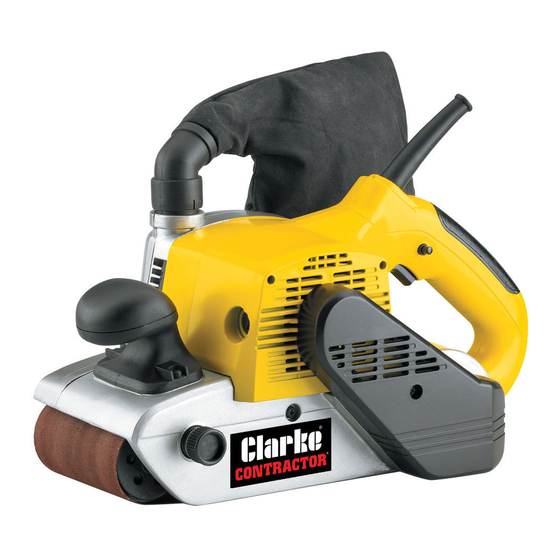
Summary of Contents for Clarke Contractor CBS2
-
Page 1: Variable Speed
VARIABLE SPEED JIG SAW BELT SANDER BELT SANDER Part No. 6460200 MODEL No. CBS2 Part No. 6462080 OPERATING & MAINTENANCE INSTRUCTIONS 0514... -
Page 2: Pack Contents
Belt Size ............610mm x 100mm This Product Conforms To 98/37/EEC Regulations Please note that the details and specifications contained herein, are correct at the time of going to print. However, CLARKE International reserve the right to change specifications at any time without prior notice. -
Page 3: Safety Precautions
SAFETY PRECAUTIONS WARNING: As with all machinery, there are certain hazards involved with their operation and use. Exercising respect and caution will considerably lower the risk of personal injury. However, if normal safety precautions are overlooked or ignored, personal injury to the operator or damage to property, may result. 1. - Page 4 16. ALWAYS have your power tool serviced by a qualified repair person using only identical replacement parts. This will ensure that the safety of the power tool is maintained. 17. NEVER operate machine while under the influence of drugs, alcohol or any medication. 18.
-
Page 5: Dust Extraction
SANDING WARNINGS WARNING! Contact with or inhalation of dust from certain materials can endanger the health of the operator and bystanders. The sanding of lead based paint is not recommended. It is difficult to control the spread of lead contaminated dust. Pre-1960 buildings may have been painted with lead based paints and then subsequently covered by additional layers of paint. -
Page 6: Electrical Connections
(as indicated by marking or colour code). Replacement fuse covers can be obtained from your local Clarke dealer or most electrical stockists. Fuse Rating The fuse in the plug must be replaced with one of the same rating (13 amps) and this replacement must be ASTA approved to BS1362. -
Page 7: Changing The Sanding Belt
PREPARATION Changing The Sanding Belt WARNING ! Disconnect the plug from the power source before changing the belt. To change the sanding belt, proceed as follows: Pull out the belt tension lever. Slide the old belt away from the rollers. Slide the new sanding belt into position over the front and rear rollers, ensuring that the arrows on the sanding belt and on the tool are pointing in the same direction. -
Page 8: Adjusting The Sanding Belt Tracking
ADJUSTING THE SANDING BELT TRACKING WARNING ! Always wear eye protection when adjusting or operating the belt sander. Having changed the belt, it is important to make sure that the belt runs square on the rollers. This is achieved by adjusting the tracking. To adjust the tracking, proceed as follows: Switch on the belt sander. -
Page 9: Operation
OPERATION Connect the plug to the mains socket and switch on. Hold the sander firmly with both hands Operating The Trigger Switch Use the trigger switch as follows: Trigger Lock-on Squeeze the trigger, the belt sander will button start. Release the trigger to stop the belt sander. -
Page 10: Maintenance
MAINTENANCE WARNING ! Make sure that the belt sander is switched off and disconnected from the mains supply before starting any cleaning or maintenance procedures. After use clean out any accumulated dust etc. Keep the cooling vents clear. If the sander should become too hot, run it for 2 minutes without load. -
Page 11: Troubleshooting
Ensure sander is switched OFF and isolated from the mains by removing plug from socket. ACCESSORIES A wide range of accessories is available from your nearest CLARKE dealer, for further information, contact your nearest dealer, or telephone CLARKE International Sales... -
Page 12: Parts Diagram
PARTS DIAGRAM... -
Page 13: Parts List
PARTS LIST Item Part Number Description Item Part Number Description HTBS2001 ScrewST4.2X16 HTBS2030 Dust control HTBS2002 Soft grip HTBS2031 Gun seal up circle HTBS2003 Hand stem cover HTBS2032 Border cover HTBS2004 Capacitor HTBS2033 Screw ST4.2X45 HTBS2005 Inductance HTBS2034 Name plate HTBS2006 Switch HTBS2035... -
Page 14: Parts And Service
PARTS LIST PARTS & SERVICE For Spare Parts and Service, please contact your nearest dealer, or CLARKE International, on one of the following numbers. PARTS & SERVICE TEL: 020 8988 7400 or e-mail as follows: PARTS: Parts@clarkeinternational.com SERVICE: Service@clarkeinternational.com Replacement sanding belts are available from your CLARKE dealer. -
Page 15: Declaration Of Conformity
DECLARATION OF CONFORMITY...


