
Related Manuals for Clarke COBS1


Summary of Contents for Clarke COBS1
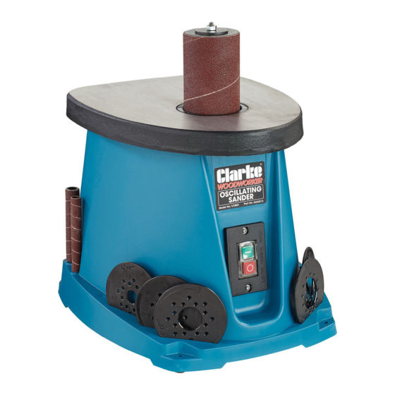
- Page 1 OSCILLATING BOBBIN SANDER MODEL NO: COBS1 PART NO: 6462013 OPERATION & MAINTENANCE INSTRUCTIONS LS1014...
-
Page 2: Environmental Recycling Policy
INTRODUCTION Thank you for purchasing this CLARKE product. Before attempting to use this product, please read this manual thoroughly and follow the instructions carefully. In doing so you will ensure the safety of yourself and that of others around you, and you can look forward to your purchase giving you long and satisfactory service. -
Page 3: Safety Symbols
CONTENTS The following items should be supplied in the carton. If any parts are missing, do not operate until the missing parts are replaced. Failure to follow this instruction could result in serious injury. 1 x Bobbin Sander 1 x 13 mm Ø Sanding Sleeve 1 x 13 mm Ø... -
Page 4: General Safety Rules
GENERAL SAFETY RULES WARNING: READ ALL INSTRUCTIONS. FAILURE TO FOLLOW ALL INSTRUCTIONS LISTED BELOW MAY RESULT IN ELECTRIC SHOCK, FIRE AND/ OR SERIOUS INJURY. 1. Keep work area clear 7. Do not force the tool • Cluttered areas and benches •... - Page 5 13. Do not overreach 19. Stay alert • Keep proper footing and • Watch what you are doing, use balance at all times. common sense and do not operate the tool when you are 14. Maintain tools with care tired. •...
-
Page 6: Electrical Connections
ELECTRICAL CONNECTIONS WARNING: READ THESE ELECTRICAL SAFETY INSTRUCTIONS THOROUGHLY BEFORE CONNECTING THE PRODUCT TO THE MAINS SUPPLY. Connect the mains lead to a standard, 230 Volt (50Hz) electrical supply through an approved 13 amp BS 1363 plug, or a suitably fused isolator switch. If the plug has to be changed because it is not suitable for your socket, or because of damage, it must be removed and a replacement fitted, following the wiring instructions shown below. -
Page 7: Parts Identification
PARTS IDENTIFICATION Table Spanner Bobbin Dust Chute Spindle Washer Bobbins + Sanding Sleeves Spindle Bobbin Sander 10 Table Inserts Parts & Service: 020 8988 7400 / E-mail: Parts@clarkeinternational.com or Service@clarkeinternational.com... - Page 8 ASSEMBLY FITTING THE SANDPAPER SLEEVE ONTO THE BOBBIN 1. Fit the sandpaper sleeve on to the bobbin as shown. NOTE: The 13mm sanding sleeve does not fit onto a bobbin, it simply slides directly onto the spindle. PARTS STORAGE 1. The storage slots on the front are used to store the table inserts.
- Page 9 • The table insert must be used at all times • If the table insert is damaged It must be replaced before use. Spare parts are available from the Clarke spare parts department. Parts & Service: 020 8988 7400 / E-mail: Parts@clarkeinternational.com or Service@clarkeinternational.com...
-
Page 10: Dust Collection
DUST COLLECTION Connect a suitable dust collector to the dust chute. USING THE SANDER WARNING: CONTACT WITH OR INHALATION OF DUST FROM LEAD BASED PAINTS CAN ENDANGER THE HEALTH OF THE OPERATOR AND BYSTANDERS, ALWAYS WEAR A SUITABLE DUST MASK WHEN USING THE SANDER. -
Page 11: Maintenance
MAINTENANCE WARNING: REMOVE THE PLUG FROM THE MAINS POWER SUPPLY BEFORE CARRYING OUT ANY ADJUSTMENT, SERVICING OR MAINTENANCE PERIODICALLY • Keep the ventilation holes clear and free from blockages. • Wipe the unit with a damp cloth, do not use abrasive chemicals to clean the sander. -
Page 12: Specifications
SPECIFICATIONS Model Number COBS1 Operating Temperature Range 0-40°C Bobbin Speed 2000 rpm Oscillations per min Oscillation Travel 16 mm Sanding Table Dimensions: (Length x Width) 370 x 295 mm Table Height 330 mm Bonnin Length 115 mm Max Bobbin Working Height... -
Page 13: Exploded Diagram
EXPLODED DIAGRAM Hex nut 10mm HTCOBS101 Lower spindle washer HTCOBS106 Upper spindle washer HTCOBS102 Cast iron table HTCOBS107 Sander sleeve HTCOBS103 Dust washer HTCOBS108 Rubber spindle HTCOBS104 Dust cover HTCOBS109 Throat plate HTCOBS105 Washer 05 HTCOBS110 Parts & Service: 020 8988 7400 / E-mail: Parts@clarkeinternational.com or Service@clarkeinternational.com... - Page 14 Wheel (I) HTCOBS154 Spring washer 05 HTCOBS111 Screw 5 x 12 HTCOBS112 Spindle HTCOBS155 HTCOBS156 Belt HTCOBS113 Belt II HTCOBS114 Wheel (II) HTCOBS157 Bearing sleeve HTCOBS158 Belt wheel HTCOBS115 Spring washer HTCOBS116 Wheel plate HTCOBS159 Screw 4.2 x 13 HTCOBS160 Tension roller assembly HTCOBS117 Screw 4.2 x 13...
-
Page 15: Declaration Of Conformity
DECLARATION OF CONFORMITY Parts & Service: 020 8988 7400 / E-mail: Parts@clarkeinternational.com or Service@clarkeinternational.com...