Siemens SENTRON PAC2200 Product Manual
7km measuring device
Hide thumbs
Also See for SENTRON PAC2200:
- Product manual (130 pages) ,
- Operating instructions manual (6 pages) ,
- Operating instructions manual (7 pages)
Table of Contents
Advertisement
Advertisement
Table of Contents

Related Manuals for Siemens SENTRON PAC2200


Summary of Contents for Siemens SENTRON PAC2200
- Page 3 ___________________ Introduction ___________________ Description ___________________ SENTRON Mounting ___________________ Connection 7KM measuring device PAC2200 ___________________ Operation ___________________ Commissioning Manual ___________________ Service and maintenance ___________________ Technical data ___________________ Dimension drawings ___________________ Appendix 05/2018 L1V30415167B-02...
- Page 4 Note the following: WARNING Siemens products may only be used for the applications described in the catalog and in the relevant technical documentation. If products and components from other manufacturers are used, these must be recommended or approved by Siemens. Proper transport, storage, installation, assembly, commissioning, operation and maintenance are required to ensure that the products operate safely and without any problems.
-
Page 5: Table Of Contents
Table of contents Introduction ..............................7 Components of the product ...................... 7 Latest information ........................7 Description ............................... 11 Features ..........................11 Measuring inputs ........................15 Averaging measured values ....................19 2.3.1 Acquisition of power demand ....................20 2.3.2 Energy counters ........................21 Digital inputs and outputs ....................... - Page 6 Table of contents Operation ..............................49 Device interface ........................49 5.1.1 Displays and operator controls ....................49 5.1.2 Control keys ........................... 50 Menu navigation ........................51 5.2.1 Measured value level ......................51 5.2.2 Main menu level ........................52 5.2.3 Setting level ..........................52 5.2.4 Editing level ..........................
- Page 7 Table of contents A.1.12 Modbus standard device identification with the function code 0x2B ........105 Index ..............................107 PAC2200 Manual, 05/2018, L1V30415167B-02...
- Page 8 Table of contents PAC2200 Manual, 05/2018, L1V30415167B-02...
-
Page 9: Introduction
● 1 x PAC2200 measuring device ● PAC2200 operating instructions: Available accessories ● SENTRON powerconfig software (https://support.industry.siemens.com/cs/document/63452759/update-version- powerconfig-v3-7?dti=0&lc=en-WW) ● SENTRON powermanager software (https://support.industry.siemens.com/cs/document/64850998/powermanager-v3-3-incl- hf1?dti=0&lc=en-WW) Latest information Up-to-the-minute information You can find further assistance: on the Internet: Website (https://support.industry.siemens.com/my/ww/en/requests) PAC2200 Manual, 05/2018, L1V30415167B-02... - Page 10 Siemensstrasse 10 93055 Regensburg Germany Internet: Technical Assistance (https://support.industry.siemens.com/My/ww/en/requests) Subject: Open Source Request (please specify Product name and version, if applicable) SIEMENS may charge a handling fee of up to 5 EUR to fulfil the request. PAC2200 Manual, 05/2018, L1V30415167B-02...
- Page 11 Product or any OSS components contained in it if they are modified or used in any manner not specified by SIEMENS. The license conditions listed below may contain disclaimers that apply between you and the respective licensor.
- Page 12 Introduction 1.2 Latest information Note Risk of manipulation Several protective mechanisms can be activated in the device. In order to reduce the risk of manipulation occurring on the device, it is recommended that the protective mechanisms available in the device are activated. •...
-
Page 13: Description
Description Features The PAC2200 is a measuring device for measuring the basic electrical variables in low- voltage power distribution. All measured variables are shown on the display of the PAC2200. The device is capable of single-phase, two-phase, or three-phase measurement and can be used in TN and TT networks. - Page 14 Description 2.1 Features Display and operator control ● LC display ● Four control keys with variable function assignment ● LED for Ethernet communication, active energy pulse indicator ● SENTRON powerconfig from Version 3.7. ● SENTRON powermanager from Version 3.4. ● Web server (HTTP) (optional) Interfaces ●...
- Page 15 Description 2.1 Features Security ● Hardware write protection ● Password protection ● Access protection, IP filter ● Modbus TCP port, configurable ● HTTP port, configurable ● DHCP protocol included ● SNTP protocol included ● Attachment of lead seals possible Using "Password protection" and "Hardware write protection", you can protect against write access to the device settings of the PAC2200.
- Page 16 Description 2.1 Features Tariffs SENTRON PAC2200 supports 2 tariffs for the integrated energy counter (on-peak and off-peak). Switching between tariffs Tariff switching can be controlled via the digital input or the communication interfaces. Time-related switching is only possible using a higher-level system.
-
Page 17: Measuring Inputs
Description 2.2 Measuring inputs Measuring inputs Current measurement NOTICE AC current measurement only The device is not suitable for measuring DC current. The 5 A device is designed for: ● Measuring current of 5 A for connecting standard current transformers. Each current measuring input can take a continuous load of 10 A. - Page 18 Description 2.2 Measuring inputs Connection types Two connection types have been provided. The device can be used in TN and IT networks. Table 2- 1 Available connection types Short code Connection type 3P4W (factory setting) 3 phases, 4 conductors, unbalanced load 1P2W (not MID devices) 1 phase, 2 conductors, unbalanced load The input circuit of the device must correspond to one of the connection types listed.
- Page 19 Description 2.2 Measuring inputs Display of the measured variables depending on the connection type The table below shows which measured values can be represented depending on the connection type. The availability of the measured variables depends on the type of readout. Depending on the device version, several different readout types are available: ●...
- Page 20 Description 2.2 Measuring inputs Connection type 3P4W 1P2W Measured variable Average voltage L - L ✓ — Average current ✓ — Binary outputs ✓ ✓ Binary inputs ✓ ✓ Tariff ✓ ✓ Counter (configurable) ✓ ✓ Active power import ✓ ✓...
-
Page 21: Averaging Measured Values
Description 2.3 Averaging measured values Connection type 3P4W 1P2W Measured variable L2 reactive energy export tariff 2 ✓ — L2 apparent energy tariff 1 ✓ — L2 apparent energy tariff 2 ✓ — L3 active energy import tariff 1 ✓ —... -
Page 22: Acquisition Of Power Demand
Description 2.3 Averaging measured values 2.3.1 Acquisition of power demand Values that can be read out ● The PAC2200 measuring device supplies the power demand of the last completed measuring period: ● Mean values for active and reactive power, separately for import and export. ●... -
Page 23: Energy Counters
Description 2.3 Averaging measured values 2.3.2 Energy counters Available energy counters of the PAC2200 measuring device: Tariff 1 Tariff 2 Total (T1 + T2) Active energy kWh Import Total Secondary value X (MID) Export Total Secondary value Reactive energy kvarh Import Total Secondary value... -
Page 24: Digital Inputs And Outputs
Description 2.4 Digital inputs and outputs Digital inputs and outputs The PAC2200 has the following inputs/outputs: ● 1 digital input ● 1 digital output 2.4.1 Digital input The following functions can be assigned to the digital input: ● Status monitoring: Capturing statuses of connected signal encoders ●... -
Page 25: Digital Output
Description 2.4 Digital inputs and outputs 2.4.2 Digital output The following functions can be assigned to the digital output: ● Not used Digital output is deactivated. ● Device is ready for operation. The digital output is ON. ● Remote control The digital input is remotely controlled. -
Page 26: Communication
Description 2.5 Communication Wiring The digital output is passive and implemented exclusively as a switch. Implementation of the pulse function corresponds to the IEC 62053-31 standard. Pulse length Turn-off time Figure 2-3 Pulse length and turn-off time ● Pulse length: Time for which the signal at the digital output is "high". -
Page 27: Ethernet
Description 2.5 Communication 2.5.1 Ethernet Permits communication via the following protocols: ● Modbus TCP The device can be configured via Modbus TCP ● Web server (HTTP) Protocol can be used to read out the measured values via web browser. ● SNTP The SNTP (Simple Network Time Protocol) is used to automatically synchronize the internal clock with a time server within the network. -
Page 28: M-Bus
Description 2.5 Communication 2.5.2 RS 485 Permits communication via the MODBUS RTU protocol. This interface features simple topology and high immunity against EMC interference. The data is transmitted differentially via two wires A and B. The third wire "COM" serves as the common ground potential. - Page 29 Description 2.5 Communication Header Structure of RSP_UD2 datagram Version 30 3-phase connection 3P4W 69 data records on 3 pag- Mapping 0 Version 31 1-phase connection 1P2W 19 data records on 1 page Mapping 0 Version 32 3-phase connection 3P4W 69 data records on 3 pag- Mapping 1 Version 33 1-phase connection 1P2W...
-
Page 30: Three-Phase Connection (3P4W)
Description 2.5 Communication 2.5.3.1 Three-phase connection (3P4W) The measurement data is presented on three pages (Mapping 0) and on four pages (Mapping 1). Multipage-capable masters can read out all three or four pages. As an example, the coding of the data record with ID 13 (connection type 3P4W, Mapping 1, i.e. - Page 31 Description 2.5 Communication Measured variable Length Format Unit (bits) Voltage L2-N FLOAT32 Voltage L3-N FLOAT32 Voltage L1-L2 FLOAT32 Voltage L2-L3 FLOAT32 Voltage L3-L1 FLOAT32 Current L1 FLOAT32 Current L2 FLOAT32 Current L3 FLOAT32 Total reactive energy import tariff 1 INT48 kvarh Total reactive energy import tariff 2 INT48...
- Page 32 Description 2.5 Communication Measured variable Length Format Unit (bits) L3 apparent energy tariff 2 INT48 kVAh Total apparent power FLOAT32 Apparent power L1 FLOAT32 Apparent power L2 FLOAT32 Apparent power L3 FLOAT32 Date/time time Measured variable Page Version 32 Version 32 Mapping 1 Mapping 1 DIF / DIFE (de-...
- Page 33 Description 2.5 Communication Measured variable Page Version 32 Version 32 Mapping 1 Mapping 1 DIF / DIFE (de- VIF / VIFE (default) fault) Current L2 0x05 0xFD 0xDC 0xFC 0x02 Current L3 0x05 0xFD 0xDC 0xFC 0x03 Total reactive energy import tariff 1 0x86 0x10 0xFB 0x02 Total reactive energy import tariff 2...
- Page 34 Description 2.5 Communication Measured variable Page Version 32 Version 32 Mapping 1 Mapping 1 DIF / DIFE (de- VIF / VIFE (default) fault) L3 apparent energy tariff 2 0x86 0x20 0xFB 0x84 0xFC 0x03 Total apparent power 0x05 0xFB 0x57 Apparent power L1 0x05 0xFB 0xD7 0xFC 0x01...
- Page 35 Description 2.5 Communication Measured variable Page Version 30 Version 30 Mapping 0 Mapping 0 DIF / DIFE VIF / VIFE Current L2 0x05 0xFD 0x5C Current L3 0x05 0xFD 0x5C Total reactive energy import tariff 1 0x86 0x10 0xFB 0x02 Total reactive energy import tariff 2 0x86 0x20 0xFB 0x02...
-
Page 36: Single-Phase Connection (1P2W)
Description 2.5 Communication 2.5.3.2 Single-phase connection (1P2W) The measurement data is presented on one page. All measurement data that can be read out via the M-BUS are listed in the following table. Measured variable Length Format Unit (bits) Total active energy import tariff 1 INT48 Total active energy import tariff 2 INT48... - Page 37 Description 2.5 Communication Measured variable ID 11: Total reactive energy export tariff 2 BYTE No. Coding Description Byte 1 0x86 DIF value format INT48 -> Inte- ger 6 bytes length Byte 2 0x20 DIFE tariff 2 Byte 3 0xFB VIF linear VIF extension -> actual VIF in first VIFE Byte 4 0x82...
- Page 38 Description 2.5 Communication Measured variable Page Version 31 Version 31 Mapping 0 Mapping 0 DIF / DIFE VIF / VIFE Secondary total active energy 0x86 0x10 0x03 (MID register) Total active energy import tariff 1 0x86 0x20 0x03 Total active energy import tariff 2 0x86 0x10 0x03 Total active energy export tariff 1...
-
Page 39: Mounting
Mounting Introduction WARNING Using devices when they are damaged may result in death, serious injury, or property damage! Do not install or start up damaged devices. Installation location The PAC2200 device is mounted on a TH35 rail (complying with EN 60715) and is intended for installation in permanently installed systems within closed rooms. -
Page 40: Installation Steps
Mounting 3.2 Installation steps Installation steps Procedure Deinstallation Tools You require the following tools to uninstall the device: ● Slotted screwdriver Procedure PAC2200 Manual, 05/2018, L1V30415167B-02... -
Page 41: Connection
Connection Safety notes Notes DANGER Hazardous Voltage Failure to observe this notice will cause death, serious injury or property damage. Turn off and lock out all power supplying this device before working on it. Note Some of the following tasks are carried out when hazardous voltage is present. For this reason, they must only be carried out by qualified personnel who are familiar with and follow the safety regulations and precautions. - Page 42 Connection 4.1 Safety notes DANGER Open transformer circuits will result in electric shock and arc flashover! Failure to observe this notice will cause death, serious injury or considerable damage to property. For the 5 A device it is only possible to measure the current via external current transformers.
-
Page 43: Connections
Connection 4.2 Connections Connections All terminals are fitted with sealable terminal covers Figure 4-1 PAC2200 (5A) pin assignment Connection Function ↑k Current I , input ° IL1 l↓ Current I , output ↑k Current I , input ° IL2 l↓ Current I , output ↑k... - Page 44 Connection 4.2 Connections Figure 4-2 PAC2200 (65A) pin assignment Connection Function ↑k Current I , input ° IL1 l↓ Current I , output ↑k Current I , input ° IL2 l↓ Current I , output ↑k Current I , input °...
-
Page 45: Connection Examples
Connection 4.3 Connection examples Connection examples Some connection examples for the following types of connection are listed below: ● 3P4W - 3 phases, 4 conductors ● 1P2W - 1 phase, 2 conductors The selection of the connection types in the device can differ according to the device version. - Page 46 Connection 4.3 Connection examples Connection examples for 5 A device (1) Three-phase measuring, four conductors, unbalanced load, with three current transformers Connection type 3P4W The fuses in the voltage measuring inputs are only used for cable protection. Grounding optional Figure 4-3 Connection type 3P4W, with three current transformers (2) Single-phase measuring, with one current transformer Connection type 1P2W...
-
Page 47: Connecting The Communication Cable
Connection 4.4 Connecting the communication cable Connection example for 65A device (1) Three-phase measurement, four conductors, direct connection to the low-voltage network The fuses in the voltage measuring inputs are only used for cable protection. Figure 4-5 Direct connection to the low-voltage network. Connecting the communication cable Depending on the device version, the following communication interfaces are available: ●... -
Page 48: Rs 485 Communication Cable
Connection 4.4 Connecting the communication cable 4.4.2 RS 485 communication cable This interface is available as an option. Always use a shielded cable for the RS 485 data cable. The data is transmitted differentially via two wires -/A and +/B. The third wire "COM" serves as the common ground potential. 1. - Page 49 Connection 4.4 Connecting the communication cable Implementation Ground the Ethernet or RS 485 cable at both ends. To do this, expose the foil shield of the cable. Connect the exposed shield to a suitable grounding point on the control cabinet, preferably a shielding bus.
-
Page 50: Gateway (Slave)
This allows devices (slaves) that are connected to the RS 485 expansion module of the PAC4200 to be connected to a device over Ethernet (master). Further information and a configuration description can be found in PAC4200 Manual (https://support.industry.siemens.com/cs/ww/en/view/34261595) (chapter 3.12). Figure 4-6 Connection of several PAC2200s to the gateway... -
Page 51: Operation
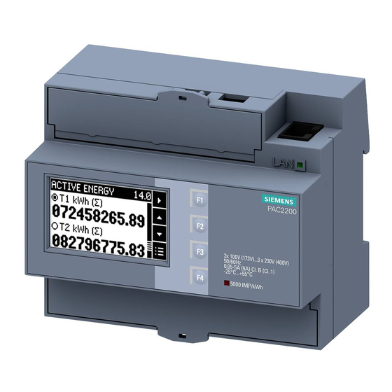
Operation Device interface 5.1.1 Displays and operator controls The front of the PAC2200 contains the following displays and operator elements. ① Software pushbutton ② LED for Ethernet: Link / Activity LED is illuminated: Data connection available • LED flashes: Data is being transferred •... -
Page 52: Control Keys
Operation 5.1 Device interface 5.1.2 Control keys The device can be operated by means of four keys. The keys are assigned different functions. The functions of the keys depend on the menu level currently in use. Keys Possible assignment Meaning No function Scroll between extended measured values Cancel the last action carried out... -
Page 53: Menu Navigation
Operation 5.2 Menu navigation Menu navigation The menu-based navigation is intuitive and self-explanatory. Therefore, only the basic structure of the menu-based navigation will be explained. To simplify the overview, menu screenshots are not included in the manual. The description and function of the individual parameters can be found in chapter 6.3 "Parameterization". -
Page 54: Main Menu Level
Operation 5.2 Menu navigation 5.2.2 Main menu level In this menu level, all available measured variables are listed without measured values. Additionally, the main menu level has a "SETTINGS" menu option for configuration of the device. key returns the device to the measured value menu level. Using the keys you can scroll through the measured variables. -
Page 55: Supporting Software
Operation 5.3 Supporting software Supporting software 5.3.1 SENTRON powermanager Using the SENTRON powermanager energy management software energy data of the PAC2200 measuring device can be acquired, monitored, evaluated, displayed and archived. SENTRON powermanager offers the following functions: ● Tree view of the customer's system (project tree) ●... - Page 56 Operation 5.3 Supporting software 5.3.2 SENTRON powerconfig The powerconfig software is the combined commissioning and service tool for communication-capable measuring devices and circuit breakers from the SENTRON family. The PC-based tool facilitates parameterization of the devices, resulting in substantial time savings, particularly when several devices have to be set up.
- Page 57 Operation 5.3 Supporting software 5.3.3 Web server The device can be read out with a PC/notebook via the website using the web server integrated in the device. Communication takes place via Modbus TCP protocol. The web server provides the following functions: ●...
- Page 58 Operation 5.3 Supporting software PAC2200 Manual, 05/2018, L1V30415167B-02...
-
Page 59: Commissioning
Commissioning Overview Prerequisites ● The device has been installed. ● The device has been connected in accordance with the possible connection methods. Steps for starting up the device 1. Apply the measuring voltage 2. Parameterize the device 3. Check measured values Note Check the connections Incorrect connection can result in malfunctions and failure of the device. -
Page 60: Applying The Measuring Voltage
Parameterizing with SENTRON powerconfig You can download the SENTRON powerconfig configuration software from the Industry Online Support Website (https://support.industry.siemens.com/cs/document/63452759/update-version-powerconfig- v3-7?dti=0&lc=en-WW). Information and notes on how to use SENTRON powerconfig can be found in the Online Help of the configuration software or by contacting Technical Support. - Page 61 Commissioning 6.3 Parameterizing the device Establishing connection to the device To establish a connection to the PAC2200, proceed as follows: 1. Connect the PAC2200 device to the PC or network. 2. When you have connected the device via Ethernet, make sure that the PAC2200 and the configuration computer are in the same subnet.
- Page 62 Commissioning 6.3 Parameterizing the device Parameterizing the device The parameters are entered and changed in offline mode. To switch between online and offline mode, press "Activate online view" in the "Options" menu item or the "F12" button. Set the required basic parameters. Note the description of the parameters in chapter 6.3.2.
- Page 63 Commissioning 6.3 Parameterizing the device "Password protection" parameter When using password information, write access is possible by means of the "powerconfig" software. The password is only required when the "Password protection" parameter is activated. As soon as the password has been entered once for the device, it is not requested again. The set password can be deleted from the memory in menu item "Password management".
-
Page 64: Setting Parameters Via The Device Menu
Commissioning 6.3 Parameterizing the device "Hardware write-protection" parameter No write access is possible, even if password information is used. In order to gain write access, the hardware write protection must be deactivated. ON: Hardware write protection is activated. OFF: Hardware write protection is deactivated Activation or deactivation of the password protection must be confirmed on the device. - Page 65 Commissioning 6.3 Parameterizing the device "Voltage Input" parameter (Not available for MID devices) Connection types: ● 3P4W: 3 phases, 4 conductors ● 1P2W: 1 phase, 2 conductors Default setting: 3P4W The "Connection type" parameter limits the total number of measured variables. The input circuit of the device must correspond to the parameterized connection type.
- Page 66 Commissioning 6.3 Parameterizing the device "Write protection" parameter The "Write protection" parameter is described later in this chapter. "Date/Time" parameter The date and time can be set by using the "Date/time" option in the "Settings" menu. Date: Displayed in accordance with the format Format: DD.MM.YYYY (default setting) MM/DD/YY...
- Page 67 Commissioning 6.3 Parameterizing the device "Integrated I/O" parameter "Digital input" parameter The following functions can be assigned to the "Digital input" parameter: ● Tariff switching for two-tariff, active energy, and reactive energy counters. ● Synchronization of the measuring period by means of the synchronization pulse of a system control center or other device.
- Page 68 Commissioning 6.3 Parameterizing the device "Digital output" parameter The following functions can be assigned to the "Digital output" parameter: ● Energy pulse output; can be programmed for active or reactive energy pulses ● Indication of the direction of rotation ● Operating state display of the device ●...
- Page 69 Commissioning 6.3 Parameterizing the device "Communication" parameter The number of available communication interfaces can vary depending on the version of the device. "MODBUS TCP" parameter The "MODBUS TCP" parameter is only available for devices with an Ethernet interface. DHCP (Dynamic Host Configuration Protocol) If the DHCP is activated, network configurations are automatically as- signed.
- Page 70 Commissioning 6.3 Parameterizing the device "MODBUS RTU" parameter (optional) The "MODBUS RTU" parameter is only available for devices with an RS 485 interface. Address 1 - 247 Baud rate 4800/9600/19200/38400 Format 8N1/8N2/8E1/8O1/ Response time 0 - 255 ms "M-BUS" parameter (optional) The "M-BUS"...
- Page 71 Commissioning 6.3 Parameterizing the device "Extended" parameter "Password" parameter The write access to the device settings can be protected by means of a password. As soon as the password has been entered once for the device, it is not requested again for as long as the device is still in the "Settings"...
- Page 72 Commissioning 6.3 Parameterizing the device "Write protection" parameter No write access is possible. In order to gain write access, the hardware write protection on the device must be deactivated. No: Hardware write protection is deactivated Yes: Hardware write protection is activated. (default setting: No) Request message "PRESS SW"...
-
Page 73: Service And Maintenance
Service and maintenance Calibration The device has been calibrated by the manufacturer before shipping. Recalibration is not required provided the environmental conditions are maintained. Firmware updates The PAC2200 supports firmware updates. An operating system update can be carried out on MID-approved devices. When updating, always use the latest version of the configuration software SENTRON powerconfig. -
Page 74: Troubleshooting Guide
If the device fault cannot be remedied by the measures given above, the device is probably defective. More help can be found on the Internet. Technical Assistance (www.siemens.de/lowvoltage/support-request) If the device is defective, please proceed as follows: ● See chapter Warranty (Page 73), if the device has become defective within the warranty period. -
Page 75: Warranty
Procedure Note Loss of warranty If you open the device, you will invalidate the Siemens warranty. Only the manufacturer is permitted to carry out repairs to the devices. Return faulty or damaged devices to Siemens for repair or replacement. If the device is faulty or damaged, proceed as follows (only during the warranty period): 1. - Page 76 Service and maintenance 7.5 Disposal PAC2200 Manual, 05/2018, L1V30415167B-02...
-
Page 77: Technical Data
Technical data Technical data Device configuration ● 1 optically isolated digital input ● 1 optically isolated digital output ● 1 Ethernet interface, for connecting and configuring to the PC or network (optional) ● 1 M-Bus connection for reading out the measured values (optional) ●... - Page 78 Technical data 8.1 Technical data Measuring inputs for voltage (5 A device) Measuring inputs Voltage U 220/230 VAC 50 / 60 Hz (MID devices only 50 Hz) Max. measurable voltage Voltage L-N AC 3~ 230 V (+20%) Voltage L-L AC 3~ 400 V (+20 %) Min.
- Page 79 Technical data 8.1 Technical data Measuring accuracy Standards applied ● IEC 61557-12 ● IEC 62053-21 ● IEC 62053-22 ● IEC 62053-23 ● EN 50470-3: Measured variable Accuracy class acc. to IEC 61557-12 (K55) Voltage Class 0.5 Current Class 0.5 Apparent power Class 1 Active power Class 1...
- Page 80 Technical data 8.1 Technical data Digital output Digital output Number Type Passive Design/function Switching output or pulse output Maximum switching voltage 30 V Output current For signal "1" Depends on the load and the external power supply Continuous load ≤50 mA (thermal overload protection) Transient overload ≤130 mA for 100 ms For signal "0"...
- Page 81 Technical data 8.1 Technical data Connection elements The specified conductor cross sections describe the capacity of the connection terminals. When selecting the conduction cross sections, always pay attention to the possible current load and ensure adequate cable protection. Current, power supply 5 A device 65 A device Conductor cross section...
- Page 82 Technical data 8.1 Technical data Dimensions and weights Dimensions and weights Type of fixing Standard rail mounting TH35 to EN 60715 Construction type Housing dimensions W x H x D 108 mm x 97 mm x 71 mm [4.2 in x 3.8 in x 2.8 in] Weight 5 A device without packaging 310 g...
- Page 83 Technical data 8.1 Technical data Environmental conditions Operation is only permissible inside an enclosed dry room. Environmental conditions Temperature range Ambient temperature during operating phase -25 °C … +55 °C (K55) Ambient temperature during transport and storage -25 °C … +70 °C Relative humidity (annual average value) <...
- Page 84 Approvals The PAC2200 complies with the requirements of the European Directives. CE conformity The SENTRON PAC2200 complies with the requirements of the following European Directives: DIRECTIVE 2014/30/EU OF THE EUROPEAN PARLIAMENT AND COUNCIL of February 26, 2014, on the harmonization of the laws of the...
-
Page 85: Labeling
Technical data 8.2 Labeling Labeling Labels on the housing of the PAC2200 ① CE mark ② MID mark with the year it was affixed ③ Number of the notified body ④ Electrical installation demands technical competence ⑤ EAC mark ⑥ Protective insulation - device of class II ⑦... - Page 86 Technical data 8.2 Labeling PAC2200 Manual, 05/2018, L1V30415167B-02...
-
Page 87: Dimension Drawings
Dimension drawings Dimensional drawings Frame dimensions Figure 9-1 Frame dimensions PAC2200 Manual, 05/2018, L1V30415167B-02... - Page 88 Dimension drawings 9.1 Dimensional drawings PAC2200 Manual, 05/2018, L1V30415167B-02...
-
Page 89: Appendix
Appendix Modbus TCP Detailed information about Modbus can be found at the Modbus Website (http://www.modbus.org) A.1.1 Function codes Function codes control the data exchange. In doing so, a function code tells the slave which action it is to take. If an error occurs, the most significant bit (MSB) is set in the FC byte of the response frame. Supported Modbus function codes Table A- 1 Supported Modbus function codes... -
Page 90: Modbus Exception Codes
Appendix A.1 Modbus TCP A.1.2 Modbus exception codes Overview Table A- 2 Modbus exception codes Exception Name Meaning Remedy codes Illegal Function Illegal function: Check which function codes are supported. The function code in the re- • quest is not a permissible ac- tion for the slave. -
Page 91: Modbus Measured Variables With The Function Codes 0X03 And 0X04
Appendix A.1 Modbus TCP A.1.3 Modbus measured variables with the function codes 0x03 and 0x04 Addressing the measured variables You can use the Modbus function codes 0x03 and 0x04 on all the measured variables listed below. Note Error in the case of inconsistent access to measured values Please ensure the start offset of the register is correct when making read accesses. - Page 92 Appendix A.1 Modbus TCP Offset Number of Name Format Unit Value range Access registers Reactive power L3 Float Power factor L1 Float 0 ... 1 Power factor L2 Float 0 ... 1 Power factor L3 Float 0 ... 1 Frequency Float 45 ...
- Page 93 Appendix A.1 Modbus TCP Offset Number of Name Format Unit Value range Access registers Reactive energy import tariff 2 Double varh Overflow 1.0e+12 Reactive energy export tariff 1 Double varh Overflow 1.0e+12 Reactive energy export tariff 2 Double varh Overflow 1.0e+12 Apparent energy tariff 1 Double Overflow 1.0e+12...
-
Page 94: Modbus-Measured Variables With Function Code "0X14
Appendix A.1 Modbus TCP A.1.4 Modbus-measured variables with function code "0x14" Addressing the measured variables The measured variables listed below can be read out via Modbus function code 0x14 "Read File Record" in two steps. Step 1 (File Number 1), preset to 10 s Step 2 (File Number 2), preset to 15 min Note Error in the case of inconsistent access to measured values... - Page 95 Appendix A.1 Modbus TCP Apparent power L2 Float Apparent power L3 Float Active power L1 Float Active power L2 Float Active power L3 Float Reactive power L1 Float Reactive power L2 Float Reactive power L3 Float Power factor L1 Float Power factor L2 Float Power factor L3...
- Page 96 Appendix A.1 Modbus TCP Maximum power factor L1 Float Maximum power factor L2 Float Maximum power factor L3 Float Maximum frequency Float Maximum average voltage L - N Float Maximum average voltage L - L Float Maximum average current Float Maximum total apparent power Float Maximum total active power...
- Page 97 Appendix A.1 Modbus TCP Minimum total active power Float Minimum total reactive power Float Minimum total power factor Float A.1.5 Structure - Digital input status and digital output status with the function codes 0x03 and 0x04 The following are available via Modbus: ●...
-
Page 98: And 0X04
Appendix A.1 Modbus TCP A.1.6 Structure - Device diagnostics and device status with the function codes 0x03 and 0x04 Structure Table A- 5 Modbus offset 205, register 2: Structure device status and device diagnostics Byte Device status Type Bit mask Value range Access No synchronization pulse... -
Page 99: Modbus Status Parameters With The Function Code 0X02
Appendix A.1 Modbus TCP A.1.7 Modbus status parameters with the function code 0x02 Status parameters You can use the Modbus function code 0x02 on all the status parameters listed below. Table A- 6 Status parameters Offset Number of Name Format Value range Access registers... -
Page 100: Modbus Settings With The Function Codes 0X03, 0X04 And 0X10
Appendix A.1 Modbus TCP A.1.8 Modbus settings with the function codes 0x03, 0x04 and 0x10 Addressing the settings You can use the Modbus function codes 0x03, 0x04 for read accesses and 0x10 for write accesses on all the settings parameters listed below. Table A- 7 Settings parameters Offset... - Page 101 Appendix A.1 Modbus TCP Table A- 8 Settings parameter for the digital input Offset Number of Name Unit Format Value range Access registers 50025 Digital input "Action" unsigned long Status only Pulse input High tariff / low tariff switching Synchronization 50029 "Pulse input"...
- Page 102 Appendix A.1 Modbus TCP Table A- 9 Settings parameter for the digital output Offset Number of Name Unit Format Value range Access registers 50033 Switching function as- unsigned long 0 ... 99 signment to a vector group 50035 Digital output "Action" unsigned long Device ON Switching output...
-
Page 103: Modbus Communication Parameters With The Function Codes 0X03, 0X04 And 0X10
Appendix A.1 Modbus TCP A.1.9 Modbus communication parameters with the function codes 0x03, 0x04 and 0x10 Addressing the communication parameters Table A- 10 Communication parameters Offset Number of Name Unit Format Applicable Value range Access registers Modbus func- tion codes 62993 SNTP server IP unsigned long... -
Page 104: Modbus Device Information With The Function Codes 0X03, 0X04 And 0X10
Appendix A.1 Modbus TCP Offset Number of Name Unit Format Applicable Value range Access registers Modbus func- tion codes 63139 MODBUS RTU data unsigned long 0 = 8N2 0x03 • bits/ parity/ stop bits 1 = 8E1 0x04 • (if RS485 port is 2 = 8O1 0x10 •... - Page 105 Version of the I&M data 2 unsigned char 0.0 ... 255.255 [64027] Supported I&M data unsigned short 00 ... FF *) 42 stands for Siemens AG Table A- 12 I&M 1-4 parameters with the function codes 0x03, 0x04 and 0x10 Offset Total regis- Number of reg-...
-
Page 106: Modbus Command Parameters
Appendix A.1 Modbus TCP A.1.11 Modbus command parameters Addressing the command parameters You can apply the Modbus function code 0x06 to the command parameters. Table A- 13 Command parameters Offset Number Name Unit Format Value range Access of regis- ters 60004 Reset energy counter unsigned short... - Page 107 Appendix A.1 Modbus TCP Offset Number Name Unit Format Value range Access of regis- ters 60009 Switching command for vector unsigned short High 0 ... 99, Low 0 ... 1 group High byte group assign- ment Low byte 1 = ON, 0 = OFF 65300 Activation of IP / Ethernet...
- Page 108 Appendix A.1 Modbus TCP PAC2200 Manual, 05/2018, L1V30415167B-02...
- Page 109 Index Function code, 87, 105 Approvals, 82 Installation location, 37 Interface Performance features, 12 Bit mask, 95, 96 Latest information Third-party software information, 8 CE conformity, 82, 82 Command parameters, 104 Communication, 78 Communication parameters, 101 Components of the product, 7 Measured value acquisition, 75 Connection elements, 79 Measured variables...
- Page 110 Index Procedure Mounting, 38 Protection class, 80 Register, 88, 89, 97, 98, 99, 100, 101, 104 Repairs, 73 Loss of warranty, 73 RS 485 interface, 78 Screw terminal, 79 Security Performance features, 13 Security information, 9 Startup, 57 Prerequisites, 57 Status parameters, 97 Technical specifications, 75 Approvals, 82...