Table of Contents
Advertisement
Advertisement
Table of Contents

Related Manuals for Siemens SENTRON PAC1020


Summary of Contents for Siemens SENTRON PAC1020
- Page 3 Introduction Description SENTRON Installation Connection 7KM Power Monitoring Device PAC1020 Commissioning Operation Equipment Manual Parameterizing Security features Service and maintenance Technical data Dimensional drawings Appendix 05/2020 L1V30610008B-01...
- Page 4 Note the following: WARNING Siemens products may only be used for the applications described in the catalog and in the relevant technical documentation. If products and components from other manufacturers are used, these must be recommended or approved by Siemens. Proper transport, storage, installation, assembly, commissioning, operation and maintenance are required to ensure that the products operate safely and without any problems.
-
Page 5: Table Of Contents
Table of contents Introduction ............................7 Components of the product ....................7 Latest information ....................... 7 General safety notes ......................8 Security information ......................9 Open Source Software ......................9 Protective mechanisms against manipulation ..............10 Technical Support ......................10 Description ............................ - Page 6 Table of contents Applying the measuring current ..................41 Checking the displayed measured values ................41 Operation ............................. 43 Device interface ......................... 43 6.1.1 Displays and operator controls ................... 43 6.1.2 Special display elements ....................44 6.1.3 Menu-based navigation ..................... 45 6.1.3.1 Measured value level ......................
- Page 7 Table of contents A.1.7 Modbus settings with the function codes 0x03, 0x04 and 0x10 .......... 84 A.1.8 Modbus communication parameters with the function codes 0x03, 0x04 and 0x10 .... 87 A.1.9 Modbus command parameters ................... 88 A.1.10 MODBUS standard device identification with the function code 0x2B ........88 Index ..............................
- Page 8 Table of contents PAC1020 Equipment Manual, 05/2020, L1V30610008B-01...
-
Page 9: Introduction
• One PAC1020 power monitoring device • A set of operating instructions for the PAC1020 Available software • SENTRON powerconfig software (https://support.industry.siemens.com/cs/ww/en/view/63452759) Available accessories • Compact bracket (7KM9900-0GA00-0AA0) • Adapter for mounting on DIN rails, display faces towards DIN rail (7KM9900-0YA00-0AA0) •... -
Page 10: General Safety Notes
Introduction 1.3 General safety notes General safety notes General safety notes DANGER Hazardous voltage. Will cause death, serious personal injury, or equipment damage. Turn off and lock out all power supplying this equipment before working on this device. WARNING Impairment of protection will result from improper use. Can cause death, serious personal injury, or equipment damage. -
Page 11: Security Information
To keep up to date with all the latest product updates, subscribe to the Siemens Industrial Security RSS Feed at (https://www.siemens.com/industrialsecurity). Open Source Software This product, solution or service ("Product") contains third-party software components. -
Page 12: Protective Mechanisms Against Manipulation
Product or any OSS components contained in it if they are modified or used in any manner not specified by SIEMENS. The license conditions may contain disclaimers that apply between you and the respective licensor. -
Page 13: Description
Description Features Area of application This is a power monitoring device for measuring the basic electrical variables in low-voltage power distribution. The power monitoring device is capable of single-phase, two-phase, or three-phase measurement and can be used in three-wire, four-wire, TN, TT, and IT systems. The power monitoring device is designed for panel mounting. - Page 14 Description 2.1 Features Display and operator control • LC display • Four control keys with variable function assignment Software support • SENTRON powerconfig Interfaces • RS485 interface • One passive digital input • One passive digital output Memory • Device parameter settings are permanently stored in the internal device memory. •...
-
Page 15: Measuring Inputs
Description 2.2 Measuring inputs Measuring inputs Current measurement NOTICE Alternating current measurement only The device is not suitable for measuring DC current. DANGER Danger of electric shock. Will cause death, serious injury or damage to property. The device is designed for connection to the low-voltage system via external current transformers. - Page 16 Description 2.2 Measuring inputs The input circuit of the device must correspond to one of the connection types listed. Select the suitable connection type for the purpose. Connection examples can be found in chapter Connection (Page 25). NOTICE The wrong system connection can cause irreparable damage to the device. Before connecting the device, make sure that the local power supply conditions match the specifications on the rating plate.
-
Page 17: Energy Counters
Description 2.3 Energy counters Measured variable Connection type 3P4W 3P3W Total active energy export ✓ ✓ Net total active energy ✓ ✓ Total reactive energy import ✓ ✓ Total reactive energy export ✓ ✓ Net total reactive energy ✓ ✓ The measured values specified in the table are displayed as instantaneous, minimum and maximum values. -
Page 18: Digital Inputs And Outputs
Description 2.4 Digital inputs and outputs Digital inputs and outputs The power monitoring device features: • One passive digital input • One passive digital output 2.4.1 Digital input The integral digital input makes it possible to detect the status of the connected sensor. ①... -
Page 19: Digital Output
Description 2.4 Digital inputs and outputs 2.4.2 Digital output Functions The following function can be assigned to the digital output: • Switching output for remote control via the interface The digital output is remotely controlled via the integral communication interface. The Modbus function codes can be found in chapter Modbus (Page 79). -
Page 20: Rs485 Interface
Description 2.5 RS485 interface Pulse length, turn-off time ① Pulse length ② Turn-off time Figure 2-5 Pulse length and turn-off time • Pulse length: Time for which the signal at the digital output is "high". The minimum pulse length is 30 ms and the maximum 500 ms. - Page 21 Description 2.5 RS485 interface Default communication settings In the as-delivered state, the following default values are set: Table 2- 3 Default Modbus RTU communication settings Setting Default value Address Baud rate 19200 Data format Response time 0 (automatic) Delaying the response time The response time of the PAC1020 may have to be delayed to enable its operation as a slave device with devices from other manufacturers on the bus.
-
Page 23: Installation
Installation Mounting location The device is intended for installation in permanently installed panels within enclosed rooms. WARNING Only operate the device in a secure location. Failure to heed this warning may cause death, serious personal injury, or equipment damage. The power monitoring device must always be operated in a lockable control cabinet or a lockable room. - Page 24 Installation Deploy the power monitoring device only where environmental conditions permit its operation: A description of permissible operating conditions can be found in chapter Technical data (Page 65). Plan additional space for: • Ventilation • Wiring • Connection of the communication cable and cable infeed on the top of the device WARNING The use of a damaged device may result in death, serious personal injury, or property damage.
-
Page 25: Panel Mounting
Installation 3.1 Panel mounting Panel mounting You require the following tool for installation: • Cutting tool for the panel cutout Additional installation accessories • Cable clamp for strain relief of the communication cable and the connecting cables at the digital inputs/outputs. 3.1.1 Mounting dimensions Mounting and clearance dimensions... -
Page 26: Deinstallation
Installation 3.2 Deinstallation Deinstallation Make sure the device has been shut down before you begin to deinstall it. Deinstallation steps Figure 3-3 Deinstallation PAC1020 Equipment Manual, 05/2020, L1V30610008B-01... -
Page 27: Connection
Connection Safety instructions Notes DANGER Hazardous voltage. Will cause death, serious personal injury, or equipment damage. Turn off and lock out all power supplying this equipment before working on this device. DANGER Open transformer circuits will result in electric shock and arc flash hazards. Will cause death, serious personal injury, or equipment damage. - Page 28 Connection 4.1 Safety instructions WARNING Hazardous voltage May cause death, serious personal injury, or equipment damage. • Always open or disconnect circuit from power-distribution system (or server) of building before installing or servicing current transformers. • The current transformers my not be installed in equipment where they exceed 75 percent of the wiring space of any cross-sectional area within the equipment.
- Page 29 Connection 4.1 Safety instructions Note Only qualified personnel are permitted to install, commission or service this device. • Wear the prescribed protective clothing. Observe the general equipment regulations and safety regulations for working with high-voltage installations (e.g. DIN VDE, NFPA 70E as well as national or international regulations).
- Page 30 Connection 4.1 Safety instructions Permissible nominal voltage and tolerance for each of the connection types Line supply systems and nominal voltages Three-phase four- Three-phase four- Three-phase three- Three-phase three- Single-phase two- Split-phase (single- wire systems wire systems wire systems wire systems wire systems phase three-wire) systems...
-
Page 31: Connections
Connection 4.2 Connections Connections Connection designations No. Connection Function No. Connection Function Ⓐ Digital inputs and outputs ⑨ Voltage measuring input - Neutral conductor Ⓑ Voltage measuring inputs ⑩ Voltage measuring input Ⓒ L+, N- Supply voltage ⑪ Voltage measuring input Ⓓ... -
Page 32: Connection Examples
Connection 4.3 Connection examples Connection examples The connection examples below show connection in: • Three-wire or four-wire systems • With/without voltage transformer The device can be operated up to the maximum permissible voltage values with or without a voltage measuring transformer. It is only possible to measure the current with current transformers. - Page 33 Connection 4.3 Connection examples Example connections 1. 3-phase measurement, 4 conductors, unbalanced load, without voltage transformer, with 3 current transformers Connection type 3P4W The fuses are only used for cable protection. All commercially available miniature circuit breakers up to 20 A (C) can be used. Connection of supply voltage Install a short-circuit device.
- Page 34 Connection 4.3 Connection examples 3. 3-phase measurement, 3 conductors, unbalanced load, without voltage transformer, with 3 current transformers Connection type 3P3W The fuses are only used for cable protection. All commercially available miniature circuit breakers up to 20 A (C) can be used. Connection of supply voltage Install a short-circuit device.
- Page 35 Connection 4.3 Connection examples 5. 3-phase measurement, 3 conductors, unbalanced load, without voltage transformer, with 2 current transformers Connection type 3P3W The fuses are only used for cable protection. All commercially available miniature circuit breakers up to 20 A (C) can be used. Connection of supply voltage Install a short-circuit device.
- Page 36 Connection 4.3 Connection examples 6. 3-phase measurement, 3 conductors, unbalanced load, with voltage transformer, with 2 current transformers Connection type 3P3W The fuses are only used for cable protection. All commercially available miniature circuit breakers up to 20 A (C) can be used. Connection of supply voltage Install a short-circuit device.
-
Page 37: Connecting To The Rs485 Bus
Connection 4.4 Connecting to the RS485 bus Connecting to the RS485 bus Procedure Connect the PAC1020 power monitoring device to the RS485 bus via the integral interface. Please pay attention here to the general topology of the two-wire line. 1. Connect all three lines to the screw terminals. 2. - Page 38 Connection 4.4 Connecting to the RS485 bus Grounding the cable shield The serial Modbus data line must be shielded. The shield must be connected to protective ground at one end of the line at least. Strive to achieve grounding of the shield on both sides. Grounding the common line The common line must be applied direct to protective ground, preferably at only one point for the whole bus.
-
Page 39: Commissioning
Commissioning Overview Prerequisites 1. The device has been installed. 2. The device has been connected in accordance with the possible connection methods. 3. The RS485 interface has been connected to the bus. Note: The RS485 interface must be connected for commissioning via the powerconfig parameterization software. -
Page 40: Applying Supply Voltage
Commissioning 5.2 Applying supply voltage Applying supply voltage A supply voltage is required to operate the device. Please consult the Technical data (Page 65) or the rating plate for the permissible supply voltage type and level. NOTICE The wrong system connection can destroy the device. Failure to heed this warning can result in damage to the device and the system. -
Page 41: Basic Parameters
Commissioning 5.3 Parameterizing the device 5.3.1 Basic parameters Set the basic parameters: • Connection type • Voltage – Direct measurement on the system or using voltage transformers – Measuring input voltage in the case of direct measurement on the system –... -
Page 42: Additional Settings
Commissioning 5.4 Applying the measuring voltage 5.3.2 Additional settings Language After first commissioning, the language of the text on the display can be set in the "LANGUAGE" submenu of the "SETTINGS" menu. Device protection against manipulation In order to reduce the risk of manipulation occurring on the device, it is recommended that the protection mechanism available in the device is activated. -
Page 43: Applying The Measuring Current
Commissioning 5.5 Applying the measuring current Applying the measuring current The device is designed for connection of current transformers with secondary currents of 1 A and 5 A. It is only possible to measure alternating currents. The current measuring inputs can each be loaded with 10 A continuously or with 100 A for 1 s. - Page 44 Commissioning 5.6 Checking the displayed measured values PAC1020 Equipment Manual, 05/2020, L1V30610008B-01...
-
Page 45: Operation
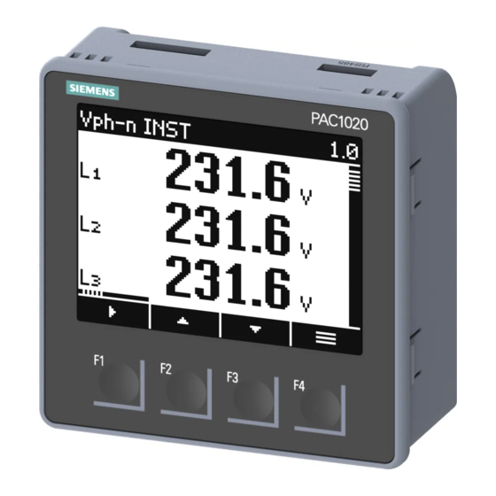
Operation Device interface 6.1.1 Displays and operator controls The front of the power monitoring device contains the following display and control elements. ① Display area: Displays the current measured values, device settings and selection menus. ② Header area: Specifies the information visible in the display area. ③... -
Page 46: Special Display Elements
Operation 6.1 Device interface 6.1.2 Special display elements ① Selection bar ② Scroll bar of function key F1 (multiple assignments of key F1) ③ Arrow up: Maximum value Arrow down: Minimum value ④ Menu name ⑤ Menu number ⑥ Scroll bar (display can be scrolled upwards/downwards) ⑦... -
Page 47: Menu-Based Navigation
Operation 6.1 Device interface 6.1.3 Menu-based navigation The menu-based navigation is intuitive and largely self-explanatory. Only the basic structure of the menu-based navigation will be explained below. The description and function of the individual parameters can be found in chapter Parameterizing (Page 49). Menu levels The device menu can be subdivided into four menu levels: •... -
Page 48: Main Menu Level
Operation 6.1 Device interface 6.1.3.2 Main menu level In this menu level, all available measured variables are listed without measured values. The main menu level also has a "SETTINGS" selection menu item which can be used to configure the device. •... -
Page 49: Control Keys
Operation 6.1 Device interface 6.1.4 Control keys The device can be operated by means of four keys. The keys are assigned different functions. The functions of the keys depend on the menu level currently in use. Keys Possible assignment Meaning Measured value level: The user uses this key to navigate to the next submenu. - Page 50 Operation 6.1 Device interface PAC1020 Equipment Manual, 05/2020, L1V30610008B-01...
-
Page 51: Parameterizing
Parameterizing Introduction Device settings The chapter headed "Parameterizing" describes the device settings. These include: • Adjustment to the physical conditions of use • Integration into the communication system • Country-specific settings, ergonomics, device protection It is possible to set the device by means of: •... -
Page 52: Parameterizing Via The Operator Interface
Parameterizing 7.2 Parameterizing via the operator interface Parameterizing via the operator interface The power monitoring device can be parameterized via the "SETTINGS" menu option. You can find more information in chapter Menu-based navigation (Page 45). The device settings are arranged into the following groups. The "SETTINGS" menu shows the choice of groups: •... -
Page 53: Device Information
Parameterizing 7.2 Parameterizing via the operator interface 7.2.1 Device information The device information cannot be modified. Device information 7KM1020-0BA01-1DA0 Article number of the device PAC1020 Vx.x.x Device designation and firmware version D/T: xxxxxx Date code ES: xxx Hardware revision level FW: xxxx Firmware revision level BL: xxxx... -
Page 54: Basic Parameters
Parameterizing 7.2 Parameterizing via the operator interface 7.2.3 Basic parameters Measuring inputs can be parameterized in the "BASIC PARAMETERS" menu item. Voltage input Selection Range Factory setting CONNECTION TYPE Selection of connection type 3P4W • 3P4W: 3 phases, 4 conductors •... - Page 55 Parameterizing 7.2 Parameterizing via the operator interface Current input Selection Range Factory setting CT PRIMARY Primary current of the current transformers 50 A 1 … 99999 A CT SECONDARY Secondary current of the current transformers • • DISPLAY RANGE Display range setting 50 A Freely adjustable 1 …...
-
Page 56: Integrated I/Os
Parameterizing 7.2 Parameterizing via the operator interface 7.2.4 Integrated I/Os Device settings for using the digital inputs and outputs. Digital output Selection Range Factory setting DIG. OUTPUT One digital output is available: – • ACTION • OFF: Output is deactivated. •... - Page 57 Parameterizing 7.2 Parameterizing via the operator interface Selection Range Factory setting Value of the cumulated power for which a config- urable number of pulses is output. The number of (with PULSE only) pulses to be output is defined in the field "PER". •...
-
Page 58: Modbus Rtu Communication
Parameterizing 7.2 Parameterizing via the operator interface 7.2.6 MODBUS RTU communication Selection Range Factory setting ADDRESS Range: 1 … 247 BAUD RATE Range: 19200 • 4800 • 9600 • 19200 • 38400 • 57600 • 115200 FORMAT • 8N1 - (8 data bits, no parity, 1 stop bit) •... -
Page 59: Display
Parameterizing 7.2 Parameterizing via the operator interface 7.2.7 Display Selection Range Factory setting CONTRAST Contrast of the LC display. 1 … 10 BACKLIGHT Switching the display backlighting on and off. • ON: Backlighting ON • OFF: Backlighting OFF DIMMED AFTER Time after which the device switches off the back- 3 min lighting. -
Page 60: Energy Counter
Parameterizing 7.2 Parameterizing via the operator interface 7.2.8 ENERGY COUNTER Selection Range Factory setting ACTIVE ENERGY Selecting the energy counter displayed on the measured value level • IMPORT: The active energy counter displays the import value. • EXPORT: The active energy counter displays the export value. -
Page 61: Advanced
Parameterizing 7.2 Parameterizing via the operator interface 7.2.9 Advanced 7.2.9.1 Password Password protection prevents the following actions: • Changing of device settings, including password • Changing and deletion of values • Deletion of data and memory content • Setting and resetting of counts •... -
Page 62: Resetting
Parameterizing 7.2 Parameterizing via the operator interface 7.2.9.2 Resetting Selection Range Factory setting CLEAR MIN/MAX VALUES Resets all minimum and maximum values to the No: not active instantaneous value. • Yes: active • No: not active FACTORY DEFAULTS All device settings and measured values except the communication parameters and energy sec- ondary values are reset to the as-delivered state. -
Page 63: Security Features
Security features The device is equipped with a protection mechanism to safeguard against deliberate and inadvertent device manipulation. • Password protection The locked padlock symbol in the title header of the display indicates that the "PASSWORD" is activated. Device is protected against write access. Device is not protected against write access. - Page 64 "PASSWORD" dialog box again in order to switch off access protection or to change the password. Note If you have forgotten the password, please contact Technical Support (https://www.siemens.com/lowvoltage/technical-support). You will be issued with a new password. PAC1020 Equipment Manual, 05/2020, L1V30610008B-01...
-
Page 65: Service And Maintenance
Service and maintenance Cleaning Clean the display and keypad regularly. Use a dry cloth for this. NOTICE Damage due to detergents Detergents can damage the device. Do not use detergents. Firmware update The power monitoring device supports firmware updates. Use the powerconfig configuration software to update the firmware. Additional information on updating the firmware can be found in the online help for powerconfig. -
Page 66: Warranty
Procedure Note Loss of warranty Opening the device invalidates the Siemens warranty. Only the manufacturer is permitted to carry out repairs to the device. If the device is defective or damaged, proceed as follows (only during the warranty period): 1. Deinstall the device. You can find more information in chapter Deinstallation (Page 24). -
Page 67: Technical Data
Technical data Device configuration • 1 optically isolated digital input • 1 optically isolated digital output • 1 RS485 interface for connecting to a PC or network Measurement Only for connection to AC voltage systems. Measurement Measuring method Voltage measurement True RMS measurement (TRMS), zero blind measurement, gapless Current measurement... - Page 68 Technical data Measuring inputs for current Only for connection to AC power systems via external current transformers. Measuring inputs for current Input current I Rated current 1 x/1 A Rated current 2 x/5 A Measuring range of current 10 … 120 % of rated current Measuring range for power and energy measurement 1 …...
- Page 69 Technical data Digital input Digital input Number Input voltage Rated value 24 V DC Maximum input voltage 30 V DC Switching thresh. signal "1" > 11 V DC Input current For "1" signal Typ. 7 mA Digital output Digital output Number Design/function Pulse output...
- Page 70 Technical data Communication RS485 interface Electrical interface RS485, two-wire line + 1 line for Common Connection type Screw terminals Supported communication pro- Modbus RTU tocol Functionality Slave Supported baud rate • 4800 • 9600 • 19200 • 38400 • 57600 •...
- Page 71 Technical data Connection components: Current connection, voltage connection Connection components: Current connection, voltage connection Conductor cross-section for copper Rigid 0.25 ... 6 mm cable (Cu) (AWG 24 … 10) Flexible 0.25 ... 6 mm (AWG 24 … 10) Flexible with end sleeve, without plastic 0.25 …...
- Page 72 Technical data Connection components: Digital inputs/outputs, RS485 interface Connection components: Digital inputs/outputs, RS485 interface Conductor cross-section for copper Rigid 1 x 0.34 … 2.5 mm cable (Cu) (AWG 22 … 14) Flexible 1 x 0.34 … 2.5 mm (AWG 22 … 14) Flexible with end sleeve, without plastic 1x 0.34 …...
- Page 73 Technical data Dimensions and weights Mounting position Vertical Weight Device without packaging Approx. 240 g Device including packaging Approx. 300 g Degree of protection and protection class Degree of protection and protection class Protection class Protection class II when installed Degree of protection according to Device front panel IP40...
- Page 74 The applied directives and standards can be found in the EU Declaration of Con- formity. Approvals for Eurasian Customs Union (valid in Russia, Belarus, Kazakhstan, Kyrgyzstan and Armenia) You can download the relevant certificates from the Siemens Support website (https://support.industry.siemens.com): PAC1020 Equipment Manual, 05/2020, L1V30610008B-01...
-
Page 75: Labeling
Technical data 10.1 Labeling 10.1 Labeling Figure 10-1 Example of a typical rating plate Item Symbol, label Explanation ① – Article number ② – Serial number of the device ③ – Device supply voltage ④ – Data about measuring inputs for voltage ⑤... - Page 76 Technical data 10.1 Labeling Item Symbol, label Explanation ⑩ – 2D code (serial number of the device) ⑪ CE marking (European Union) EAC: EAC marking (Eurasian Economic Union) ⑫ – Data about measuring inputs for current PAC1020 Equipment Manual, 05/2020, L1V30610008B-01...
- Page 77 Technical data 10.1 Labeling PAC1020 Equipment Manual, 05/2020, L1V30610008B-01...
-
Page 79: Dimensional Drawings
Dimensional drawings Panel cutout Figure 11-1 Panel cutout Frame dimensions Figure 11-2 Frame dimensions PAC1020 Equipment Manual, 05/2020, L1V30610008B-01... - Page 80 Dimensional drawings Clearance measurements L = 5 mm if compact brackets available to order as separate components are used (article num- ber: 7KM9900-0GA00-0AA0) PAC1020 Equipment Manual, 05/2020, L1V30610008B-01...
-
Page 81: Appendix
Appendix Modbus Detailed information about Modbus can be found at the Modbus website (http://www.modbus.org). A.1.1 Function codes Function codes control the data exchange. To do this, a function code tells the slave which action it is to take. If an error occurs, the MSB bit is set in the response frame in the FC byte. Supported Modbus function codes Table A- 1 Supported Modbus function codes... -
Page 82: Exception Codes
Appendix A.1 Modbus A.1.2 Exception codes Overview Table A- 2 Modbus exception codes Exception codes Name Meaning Remedy Illegal Function Illegal function: Check which function codes are supported. • The function code in the request is not a permis- sible action for the slave. •... - Page 83 Appendix A.1 Modbus Table A- 3 Meaning of the abbreviations in the "Access" column of the table headed "Available measured variables" below Abbreviation Meaning Read; read access Write; write access Read Write; read and write access Table A- 4 Available measured variables Offset Number of Name...
- Page 84 Appendix A.1 Modbus Offset Number of Name Format Unit Value range Access registers max. reactive power L1 (Q1) float max. reactive power L2 (Q1) float max. reactive power L3 (Q1) float max. power factor L1 float 0 - 1 max. power factor L2 float 0 - 1 max.
-
Page 85: Structure - Digital Input Status And Digital Output Status With The Function Codes 0X03 And 0X04
Appendix A.1 Modbus Offset Number of Name Format Unit Value range Access registers 2803 active energy (import, export, net) float overflow 1.0e+12 set: only >= 0.0 2805 reactive energy (import, export, net) float overflow 1.0e+12 set: only >= 0.0 A.1.4 Structure - Digital input status and digital output status with the function codes 0x03 and 0x04 The following are available via Modbus:... -
Page 86: Modbus Status Parameters With The Function Code 0X02
Appendix A.1 Modbus A.1.6 Modbus status parameters with the function code 0x02 Status parameters You can use the Modbus function code 0x02 on all the status parameters listed below. Table A- 7 Status parameters Offset Number of Name Format Value range from ... Access registers Bit 0 relevant parameters changed... - Page 87 Appendix A.1 Modbus Offset Number of Name Format Unit Value range from ... to Access registers to value (software) read only / read write 50011 2 Primary current unsigned long 1 … 99999A 50013 2 Secondary current unsigned long 1, 5 50019 2 Current direction unsigned long...
- Page 88 Appendix A.1 Modbus Offset Number of Name Format Unit Value range from ... to Access registers to value (software) read only / read write 50047 2 Active language unsigned long 1, 2, 4, 8 • 1 = English • 2 = Portuguese •...
-
Page 89: Modbus Communication Parameters With The Function Codes 0X03, 0X04 And 0X10
Appendix A.1 Modbus A.1.8 Modbus communication parameters with the function codes 0x03, 0x04 and 0x10 Addressing the communication parameters Table A- 9 Addressing the communication parameters Offset Number of Name Format Unit Value range from Access registers ... to 63019 ModbusRTU address unsigned long 1 …... -
Page 90: Modbus Command Parameters
Appendix A.1 Modbus A.1.9 Modbus command parameters Addressing the command parameters You can use Modbus function code 0x06 on the command parameters. Table A- 11 Command parameters Offset Number of Name Format Value range Access registers 60002 reset maxima unsigned short 60003 reset minima unsigned short... -
Page 91: Index
Index Exception code, 80 Ambient conditions, 71 Frame dimensions, 77 Function code, 79, 88 Cleaning, 63 Clearance measurements, 78 Command parameters, 88 General safety notes, 8 Commissioning, 37 Prerequisites, 37 Communication, 18, 35, 68 Communication parameters, 87 Installation Connection Procedure, 23 RS485 interface, 35 Installation space Connection components, 69... - Page 92 Index Technical Support, 10 Turn-off time, 18 Panel cutout Dimensions, 77 Parameter Status, 84 Parameterizing Ventilation Device settings, 49 Installation space, 21 Parameters Command, 88 Communication, 87 Device information, 88 Prerequisites Commissioning, 37 Procedure Installation, 23 Protection class, 71 Register, 80, 84 Repair, 64 Loss of warranty, 64 RS485 interface, 18, 35, 68...