Blodgett 900 Series Installation Manual
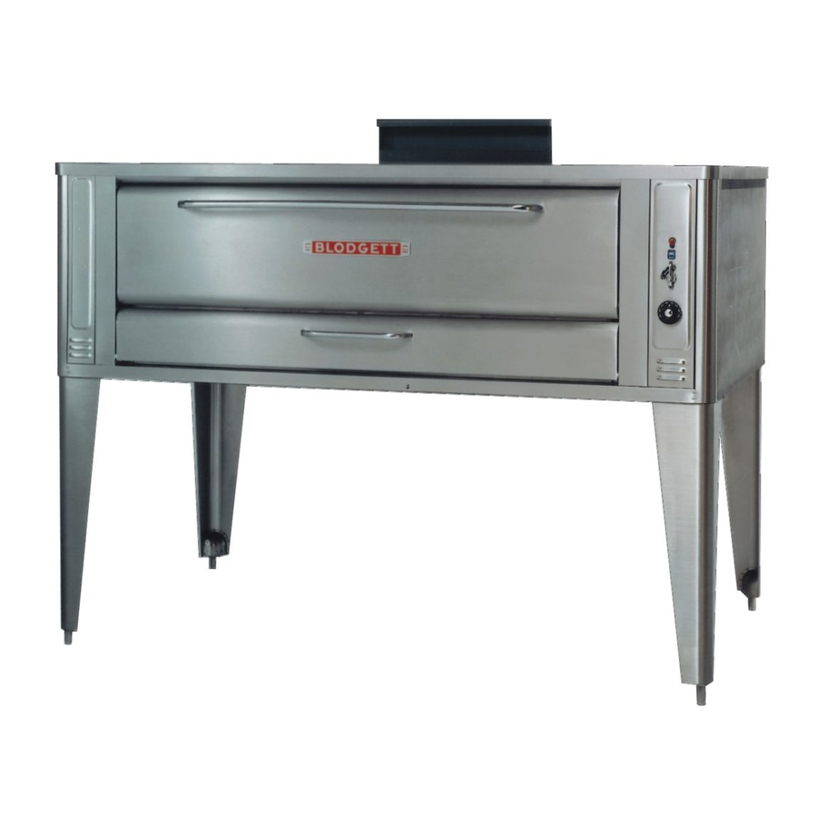
Deck oven
Hide thumbs
Also See for 900 Series:
- Installation & operation manual (45 pages) ,
- Installation operation & maintenance (78 pages) ,
- Replacement parts list manual (9 pages)
Table of Contents
Advertisement
Available languages
Available languages
Quick Links
DECK OVEN INSTALLATION
FOURS À RÔTIR, D'INSTALLATION
WARNING: IMPROPER INSTALLATION, ADJUSTMENT, ALTERATION, SERVICE OR MAINTENANCE CAN CAUSE
PROPERTY DAMAGE, INJURY OR DEATH. READ THE INSTALLATION, OPERATING AND MAINTENANCE IN-
STRUCTIONS THOROUGHLY BEFORE INSTALLING OR SERVICING THIS EQUIPMENT.
INSTRUCTIONS TO BE FOLLOWED IN THE EVENT THE USER SMELLS GAS MUST BE POSTED IN A PROMINENT
LOCATION. THIS INFORMATION MAY BE OBTAINED BY CONTACTING YOUR LOCAL GAS SUPPLIER.
FOR YOUR SAFETY Do not store or use gasoline or other flammable vapors or liquids in the vicinity of this or any other
appliance.
The information contained in this manual is important for the proper installation, use, and maintenance of this oven.
Adherence to these procedures and instructions will result in satisfactory baking results and long, trouble free service.
Please read this manual carefully and retain it for future reference.
Errors: Descriptive, typographic or pictorial errors are subject to correction. Specifications are subject to change without
notice.
AVERTISSEMENT: UNE INSTALLATION, UN AJUSTEMENT, UNE ALTERATION, UN SERVICE OU UN ENTRETIEN
NON CONFORME AUX NORMES PEUT CAUSER DES DOMMAGES A LA PROPRIETE, DES BLESSURES OU LA
MORT. LISEZ ATTENTIVEMENT LES DIRECTIVES D'INSTALLATION, D'OPERATION ET D'ENTRETIEN AVANT DE
FAIRE L'INSTALLATION OU L'ENTRETIEN DE CET EQUIPEMENT.
LES INSTRUCTIONS A RESPECTER AU CAS OU L'UTILISATEUR PERQOIT UNE ODEUR DE GAZ DOIVENT ETRE
AFFCHEES DANS UN ENDROIT BIEN VISIBLE. VOUS POUVEZ VOUS LES PROCURER AUPRES DE VOTRE
FOURNISSEUR DE GAZ LOCAL.
AVERTISSEMENT Ne pas entreposer ni utiliser de l'essence ni d'autres vapeurs ou liquides inflammables dans le voi-
sinage de cet appariel, ni de tout autre appareil.
Les informations donnees dans le present manuel sont importantes pour installer, utiliser et entretenir correctement ce
four. Le respect de ces instructions et procedures permettra d'obtenir de bons resultats de cuisson et une longue duree
de service sans problemes. Veuillez lire le present manuel et le conserver pour pouvoir vous y reporter a l'avenir.
Erreurs: Les erreurs de description, de typographie ou d'illustration font l'objet de corrections. Les caracteristiques sont
sujettes a modifications sans preavis.
44 Lakeside Avenue, Burlington, Vermont 05401 USA Telephone: (802) 658-6600 Fax: (802)864-0183
IMPORTANT
BLODGETT OVEN COMPANY
www.blodgett.com
PN 55271 Rev A (9/11)
© 2011 - G.S. Blodgett Corporation
Advertisement
Table of Contents

Related Manuals for Blodgett 900 Series


Summary of Contents for Blodgett 900 Series
- Page 1 Erreurs: Les erreurs de description, de typographie ou d’illustration font l’objet de corrections. Les caracteristiques sont sujettes a modifications sans preavis. BLODGETT OVEN COMPANY www.blodgett.com 44 Lakeside Avenue, Burlington, Vermont 05401 USA Telephone: (802) 658-6600 Fax: (802)864-0183 PN 55271 Rev A (9/11) © 2011 - G.S. Blodgett Corporation...
-
Page 2: Delivery And Location
The Blodgett Oven Company cannot assume responsibility for loss or damage suffered in transit. The carrier as- sumed full responsibility for delivery in good order when the shipment was accepted. We are, however, prepared to assist you if filing a claim is necessary. -
Page 3: Oven Assembly
A back pipe of appropriate length with either a natural gas or propane gas regulator attached Additional Packaging • Ultra Rokite decks for all 900 Series are packed in a separate crate. • The top section of multiple section ovens will always have the crown angle in position. -
Page 4: Leg Attachment
OVEN ASSEMBLY LEG ATTACHMENT 1. Put the oven onto a lift with the bottom of the oven down. 2. Each leg is attached by three bolts to the underside of the oven base frame. Figure 1 CASTER ATTACHMENT 1. Bolt supports to oven with 1/2-13 hex head bolts (casters with brakes should be facing front of oven.) 2. - Page 5 OVEN ASSEMBLY DOUBLE SECTION ASSEMBLY - 900 SERIES 1. Place lower section in predetermined place of installation. 2. Attach the legs (and casters if applicable) as previously described. 3. Using two 1” boards, place one near the edge of the oven and the other at the far side of the flue collar.
-
Page 6: Piece Deflector Assembly
OVEN ASSEMBLY DOUBLE SECTION ASSEMBLY - 1048 AND 1060 1. Fasten 12” (305 mm) legs to lower section. 2. Remove the sheet metal flue cover on bottom of UPPER SECTION FLUE ONLY and save the two screws. 3. Fasten crown angle leg frame to upper sections. 4. - Page 7 OVEN ASSEMBLY DECK SEAL - 1048 & 1060 ONLY 1. Place the long lip of the deck seal in front of the shelf support angle. Place the shorter lip with the notches between the shelf support angle and the shelf. 2.
- Page 8 OVEN ASSEMBLY STEAM INJECTION - 900 SERIES ONLY 3/8” steam connection As an optional feature, all 900 Series ovens may be sup- on back of oven plied with steam jets for baking hard rolls, and vienna, french or other hard crusted breads. This item is also available as a kit which may be installed in the field.
-
Page 9: Canopy Type Exhaust Hood
VENTILATION Blodgett gas deck ovens are direct fired. Heat and flue products from the burners are introduced directly into the baking compartment. As a result, improper venting can have a detrimental effect on the baking characteristics of the oven. A prop- erly designed ventilation system will allow the oven to function properly, while removing unwanted vapors and products of combustion from the operating area. -
Page 10: Direct Flue Arrangement
VENTING PROBLEMS Blodgett gas deck ovens use the natural principal of heat rising as the basic method of ventilation. If the venting of any deck oven is either restricted or forced in any way the baking characteristics of the oven will be adversely affected. -
Page 11: Gas Connection
13.0 1.43 2.61 2.74 3.23 Manifold Pressure W.C. 5.0 (900 series) 3.5 (1048 & 1060) 10.0 1.24 (900 series) .87 (1048 & 1060) 2.49 • Inlet Pressure - the pressure of the gas before it reaches the oven. • Manifold Pressure - the pressure of the gas as it enters the main burner(s). -
Page 12: Livraison Et Implantation
été conservé afin d’être inspecté. La Blodgett Oven Co., n’est pas responsable des dégâts subis pendant le transport. Le transporteur est seul re- sponsable de la livraison du matériel en bon état lorsque l’expédition a été acceptée. Néanmoins, nous sommes à... -
Page 13: Montage Du Four
MONTAGE DU FOUR EMBALLAGE Avant de commencer le montage du four il faut vérifier que tous ses composants sont présents. En plus du four, lui-méme, il faut des pieds, un système de ventilation et/ou d’autres accessoires. Les fours de la série 900 sont emballés de la façon suivante: Pour les sections simples: Les pièces suivantes sont emballées dans le four: •... -
Page 14: Assemblage Des Pieds
MONTAGE DU FOUR ASSEMBLAGE DES PIEDS 1. Pousser le four, couché sur le dos, sur un élévateur. 2. Chaque pied est fixé par trois boulons sous la base du four. Figure 10 FIXATION DES ROULETTES 1. Boulonnez les supports à celui-ci au moyen de boulons de 1/2-13 à tête hex (les roulettes freinées doivent être tournées vers le devant du four). - Page 15 MONTAGE DU FOUR MONTAGE DE LA SECTION DOUBLE - LA SÉRIE 900 1. Mettre la section inférieure à l’emplacement déterminé. 2. Fixer les pieds (et les roulettes, le cas échéant) comme décrit ci-dessus. 3. Prendre deux planches de 1 po. cm; en mettre une près du bord du four et l’autre planche au côté éloigné de la bague du tuyau.
-
Page 16: Montage Du Déflecteur En Trois Parties
MONTAGE DU FOUR MONTAGE DE LA SECTION DOUBLE - 1048 ET 1060 1. Fixer les pieds de 12” (305 mm) à la section du bas. 2. Retirer la gaine de métal qui recouvre le tuyau au bas de la SECTION SUPERIEURE DU TUYAU SEULEMENT et conserver les deux vis. - Page 17 MONTAGE DU FOUR JOINT DE PLAQUE- 1048 ET 1060 SEULEMENT 1. Placer la partie longue de la lèvre du joint devant l’angle de support du plateau. Placer la partie courte de la lèvre qui a des encoches entre l’angle du support de plaque et la plaque. 2.
- Page 18 MONTAGE DU FOUR INJECTION DE VAPEUR - LA SÉRIE 900 SEULEMENT Raccord de vapeur 3/8 po. Tous les fours de la série 900 offrent l’option de gicleurs à l’arrière du four de vapeur pour cuire des petits pains et d’autres pains croustillants comme des baguettes.
-
Page 19: Hotte D'évacuation Type Voûte
VENTILATION Un système de ventilation planifié et installé est absolument nécessaire car il permet un bon fonctionnement du four tout en débarassant la surface de travail des buées et résidus de combustion. Il y a deux méthodes de ventilation acceptables pour le four: •... -
Page 20: En Prise Directe
VENTILATION EN PRISE DIRECTE Quand l’installation d’une hotte aspirante mécanique est impossible ou peu pratique à réaliser, on peut ventiler le four au moyen d’une installation en prise directe. AVERTISSEMENT!! Quand on utilise un système à prise directe il faut absolument suivre le schéma. Une installation de ven- tilation à... -
Page 21: Branchement De Gaz
BRANCHEMENT DE GAZ RÉGLAGE ET TEST DE PRESSION Tous les fours sont réglés en usine en fonction du type de gaz spécifié sur la plaque signalétique. GAS RATINGS Gaz Naturel Gaz Propane Pression à l’entrée W.C. 10.5 11.0 13.0 1.43 2.61 2.74 3.23...