
Related Manuals for Cleveland SSE-25-L


Summary of Contents for Cleveland SSE-25-L
- Page 1 CLEVELAND INSTALLATION, OPERATION AND REPAIR MANUAL CLEVELAND RANGE INC. 1333 East 179th St. Cleveland. Ohio U.S.A. 44110 (216)481-4900 9209 REV:1 213-01CC KET-06...
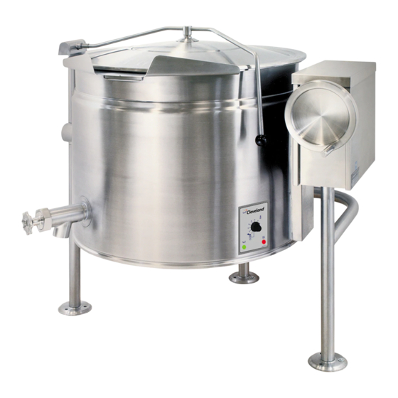
- Page 2 CLEVELAND INSTALLATION, OPERATION AND MAINTENANCE INSTRUCTIONS FOR ELECTRIC SELF-CONTAINED KETTLES FLOOR MODELS KEL-25 KEL-25-T SSE-25-L SSE-25-T KEL-40 KEL-40-T SSE-40-L SSE-40-T KEL-60 KEL-60-T SSE-60-L SSE-60-T KEL-80 KEL-80-T SSE-80-L SSE-80-T KEL-100 KEL-100-T SSE-100-L SSE-100-T RETAIN THIS MANUAL FOR YOUR REFERENCE...
-
Page 3: Installation Instructions
INSTALLATION INSTRUCTIONS Fill out all carrier claims forms and have the examining carrier sign and date each form. WARNING: Installation of this kettle must be accompanied by qualified electrical installation personnel INSTALLATION working to all applicable local and national codes. Improper installation of this product could The first installation step is to refer to the cause injury or damage. -
Page 4: Installation Check
TILTING MODELS ELECTRIC SERVICE CONNECTION Remove the screw at the rear of the console Install in accordance with local codes and/or the cover and remove the cover. A wiring diagram is National Electric Code ANSI/NFPA No. 70-1990 affixed to the underside of the console cover. (USA) or the Canadian Electric Code CSA Feed permanent copper wiring through the cut- Standard C22.1 (Canada). -
Page 5: Kettle Venting Instructions
If the kettle is a tilting model, tilt the kettle forward. The red "low water" light should be lit when the kettle is in a tilted position. This light indicates that the heater elements are not submerged in water, and they have automatically been shut off by the kettle's safety circuit. -
Page 6: Reservoir Fill Procedures
To check the gauge for proper vacuum after On tilting kettles, it is normal for the red light to venting, the temperature can be quickly reduced come on when the kettle is in a tilted position, as by filling the kettle with cold water. the elements are not submerged in water at this point. - Page 7 NOTE: When cooking egg and DISTILLED WATER REQUIREMENTS milk products, the kettle should not be preheated, as products of this When Red When the nature adhere to hot "Low Water Light'' Reservoir is Comes on, Add Completely Empty, cooking surfaces, These Kettle Distilled Water Add Distilled Water...
-
Page 8: Care And Cleaning
Pour the contents of the kettle into an WARNING: Do not use chloride base appropriate container by opening the detergents. draw-off valve or tilting the kettle Prepare a warm water and mild detergent forward. Care should be taken to pour slowly enough to avoid splashing off the solution in the kettle. -
Page 9: Maintenance
ELECTRIC KETTLE Rinse kettle interior thoroughly, then CALIBRATING PROCEDURE dram the rinse water. Insure the unit has a vacuum before you Leave the cover off when the kettle is begin calibrating procedures. If unit not in use. requires venting refer to "KETTLE Using mild soapy water and a damp VENTING INSTRUCTIONS'' in this manual. -
Page 10: Operating Controls And Indicators
OPERATING CONTROLS AND INDICATORS ITEM NO. DESCRIPTION FUNCTION On-Off Toggle Switch Controls electrical power to kettle. ( Pg. 213-09DR ) Solid State Temperature Control Knob This control knob allows the operator to select kettle heat increments from Min. to Max.(see ( Pg. - Page 11 PARTS LIST - KETTLE BOTTOM ITEM NO. PART NO. DESCRIPTION QTY. F105025 Bleed vent elbow KE50570 Bleed vent nut F105022 Connector KE50556 Probe, low water KE51723 Safety valve, 50 PSI, 1/2" KE50997 Blow down tub KE51226 Wire connector terminal KF51225 Edge connector KE00458 Solid state control box...
- Page 12 KETTLE BOTTOM...
- Page 13 PARTS LIST - CONTROL HOUSING ITEM NO. PART NO. DESCRIPTION QTY. FA11134 Screw, 10-24 x 3/8"SS KE50325 Console cover FA95008 Locknut, 3/4-16 FA30088 Washer, 1 1/2-OD x 13/16"ID x .125"W See note KE50752 Transformer, 240/16V KE50315 Worm FA95005 Tension pin KE50375 Tilt shaft FA19186...
-
Page 14: Control Housing
CONTROL HOUSING... - Page 15 PARTS LIST- POWER TILT OPTION ITEM NO. PART NO. DESCRIPTION QTY. KE51012 Gear box lid FA11134 Screw, 10-24 x 3/8" SS KE50577 Motor KE51224 Transformer, 208/120V(HG3J) KE52386 Transformer, 220, 240/120V(HG5J) KE50583 Buna-N insert KE50582 Coupling KE50377 Terminal block section (Large, white) SK50055 Terminal block section (Small, black)
- Page 16 POWER TILT OPTION...
- Page 17 PARTS LIST - TRUNNION ASSEMBLY ITEM NO. PART NO. DESCRIPTION QTY. KE00354-D Trunnion bearing casting KE00351-D Trunnion bearing casting KE00349 Bolt, 5/16-18 x 1/2" KE50666 Spherical washer...
- Page 18 PARTS LIST - 2" TANGENT DRAW-OFF VALVE ITEM NO. PART NO. DESCRIPTION QTY. 1. to 7. KE50972-B Draw-off assembly FA21008 Hex nut FA95049 Wing nut KE527551 Knob KE52754 Hex nut KE52753 Retainer KE52752 Piston FA00111 "O" Ring KE52751 Valve body...
- Page 19 PARTS LIST - FAUCET ITEM NO. PART NO. DESCRIPTION QTY. 3/4" Spout KE50833 for KS-E-LA KE50828 for KT-20-EA KE50829 for KT-30-EA, KT-4O-EA, KT-60-EA KE51404 Spout nut, short(used on spout KE50833) KE51736 Spout nut, tall (used on spouts KE50828, KE50829 and KE50830) FA95022 Retaining ring FA00016...
- Page 20 PARTS LIST - HINGE ASSEMBLY ITEM NO. PART NO. DESCRIPTION QTY. 1.-9. SE00057 Hinge assembly (40 gal. and under) SE00058 Hinge assembly (60 gal. and over) KE51218 Body, spring assist hinge KE50824 Hinge bearing KE50823 Pin (hinge) KE50820 Insert, brass adjustment KE50819 End piece FA11507...
- Page 21 ALL KETTLES AND SKILLETS HINGE ADJUSTMENT INSTRUCTIONS Insert 3/8" Allen wrench. Turn clockwise to relieve tension on spring. While tension is released remove one of the two slotted screws. To prevent Allen wrench from springing back abruptly while the second slotted screw is removed, insert a pin (approximately 1/8") in the hole where the first slotted screw was removed from.
- Page 22 ALL ELECTRIC KETTLES SERVICING GUIDE This section contains servicing information intended for use by Authorized Service Personnel. Note 1: If Fault Isolation Procedure is required, be sure to start at step #1. Note 2: On table top kettles the entire control mounting panel may be removed from kettle control housing for easier troubleshooting and pans replacement.
- Page 23 Measure continuity across safety thermostat. Replace defective safety thermostat. Is it an open circuit? Go to step #6. Is there 120 VAC present across the coils of Replace defective contactor/s. the contactors? Replace defective 12 VDC relay. Remove wire from low water level probe Clean or replace defective low water level and ground it to the body of the kettle.
- Page 24 B/ Problem: Kettle heats too slowly or not hot enough. (Note: normal max. operating pressure with an empty kettle is 25-30 psi.) Possible Causes Air in kettle jacket-requires venting. 5. Defective contactors. Defective safety thermostat. 6. Defective control box. Defective potentiometer. 7.
- Page 25 Turn the potentiometer on the control box Kettle is operating properly. clockwise to increase the max. operating Spray contact cleaner on control terminals temperature. Does the kettle now achieve and edge connector. Try box again. If max. operating pressure of 25-30 psi in an problem still exists, replace defective empty kettle? control box.
- Page 26 D/Problem: Red LED remains illuminated even though water has been added. Possible Causes Defective low water level probe. Defective control box. Fault Isolation Procedure Step Test Result Reme dy Remove wire from low water level probe Replace or clean defective low water and ground the wire to the body of the level probe.
- Page 27 STANDARD NORTH AMERICAN WIRING DIAGRAM For electrical supply other than shown above, refer to the wiring diagram affixed to the underside of the console cover. NOTE: Please reference electrical codes in your area for the correct wire and circuit breaker sizing.
- Page 28 STANDARD EUROPEAN WIRING DIAGRAM For electrical supply other than shown above, refer to the wiring diagram affixed to the underside of the console cover. NOTE: Please reference electrical codes in your area for the correct wire and circuit breaker sizing.
- Page 29 HARRISONS & CROSFIELD (CANADA) LTD. MATERIAL SAFETY DATA SHEET PRODUCT: ETHYLENE GLYCOL DATE: 24 October 1986 SUPPLIER: Harrisons & Crosfield (Canada) Ltd. 777 Supertest Road, Downsview, Ontario, M3J 2M5 Phone (416) 736 9299, Telex 06-524509 Emergency Phone (416) 667 8074 I.
- Page 30 PRODUCT: ETEYLENE GLYCOL DATE: 24 October 1986 FIRST AID: EYES: Flush with water for at least 15 minutes. SKIN: Remove contaminated clothing and flush skin with water. INHALATION: Remove to fresh air. Call a physician if discomfort persists. INGESTION: If conscious, give two glasses of water and induce vomiting. Call a physician. NOTES TO PHYSICIAN: The principle toxic effect of the material, when swallowed, will be due to the ethylene glycol content, which caused kidney damage.
-
Page 31: Additional Information
PRODUCT: ETEYLENE GLYCOL DATE: 24 October 1986 VII. SPILLS & LEAK PROCEDURES STEPS TO BE TAKEN IF MATERIAL IS RELEASED OR SPILLED: Wear suitable protective equipment. Small spills - flush with large quantities of water. Large spills - collect for disposal. WASTE DISPOSAL METHODS: Incinerate in a furnace where permitted by Federal, Provincial, and local laws and regulations. -
Page 32: Material Safety Data Sheet
FINNAN ENGINEERED PRODUCTS LIMITED POISON CONTROL CENTER EMERGENCY Tel. No. (416) 438-6070 Toronto: l-800-268-9017 Quebec (416) 294-5237 MATERIAL SAFETY DATA SHEET (416) 497-5512 : 418-656-8090 City April 28/89 SECTION I PRODUCT INFORMATION NAME OF PRODUCT FINNAN 1524L and 1529L PURPOSE OF PRODUCT Closed System Corrosion Inhibitor CHEMICAL NAME Mixture... -
Page 33: Section Viii Spill Or Leak Procedures
SECTION V HEALTH HAZARD DATA A - EFFECTS OF ACUTE OVEREXPOSURE (A) SKIN Corrosive to skin, may cause dermatitis. (B) INHALATION For nitrite , 4 hr. LC50 in rats: 1.45 mg/litre of air. (C) INGESTION Harmful or fatal if swallowed. (D) EYES Corrosive to eyes. - Page 34 SECTION IX PROTECTION INFORMATION RESPIRATORY PROTECTION: LOCAL MECHANICAL EXHAUST EXHAUST GLOVES APRONS SAFETY CHEMICAL FACE GOGGLES GLASSES SHIELD OTHER PROTECTIVE EQUIPMENT: Eyewash station. SECTION X REACTIVITY DATA STABILITY STABLE UNSTABLE HAZARDOUS DECOMPOSITION OR COMBUSTION PRODUCTS Toxic brown nitrogen dioxide gas is formed. CONDITIONS TO AVOID Mixing with acids or strong oxidizing chemicals must be avoided.