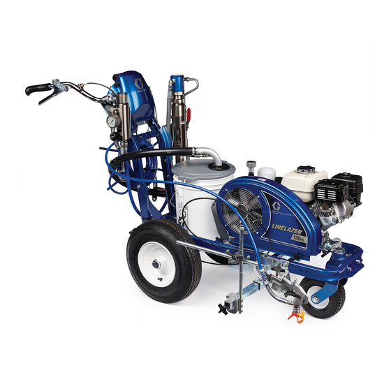
Graco LineLazer 130HS Operation
Airless line stripers
Hide thumbs
Also See for LineLazer 130HS:
- Installation manual (10 pages) ,
- Repair parts list manual (32 pages)
Table of Contents
Advertisement
Operation
™
LineLazer
For the application of line striping materials.
For professional use only.
For outdoor use only.
Not for use in explosive atmospheres or hazardous locations.
Maximum Operating Pressure: 3300 psi (22.8 MPa, 228 bar)
Important Safety Instructions
Read all warnings and instructions in this manual and in related manuals.
Be familiar with the controls and the proper usage of the equipment.
Save these instructions.
LineLazer 130
Model:
Standard
1 Manual Gun
17H447
17H448
Related Manuals:
3A3391
Parts
311254
Gun
311845
Pump
Use only genuine Graco replacement parts.
The use of non-Graco replacement parts may void warranty.
130
Airless Line Stripers
HS
HS
Standard
2 Manual Guns
3A3392B
EN
ti28037a
Advertisement
Table of Contents

Related Manuals for Graco LineLazer 130HS


Summary of Contents for Graco LineLazer 130HS
- Page 1 Save these instructions. LineLazer 130 Model: Standard Standard 1 Manual Gun 2 Manual Guns 17H447 17H448 Related Manuals: 3A3391 Parts 311254 311845 Pump ti28037a Use only genuine Graco replacement parts. The use of non-Graco replacement parts may void warranty.
-
Page 2: Table Of Contents
Component Identification (LL 130HS) ..7 LineLazer 130HS ......18 Grounding Procedure Troubleshooting . -
Page 3: Warnings
• Check hoses and parts for signs of damage. Replace any damaged hoses or parts. • This system is capable of producing 3300 psi. Use Graco replacement parts or accessories that are rated a minimum of 3300 psi. • Always engage the trigger lock when not spraying. Verify the trigger lock is functioning properly. - Page 4 Warnings CARBON MONOXIDE HAZARD Exhaust contains poisonous carbon monoxide, which is colorless and odorless. Breathing carbon monoxide can cause death. • Do not operate in an enclosed area. EQUIPMENT MISUSE HAZARD Misuse can cause death or serious injury. • Do not operate the unit when fatigued or under the influence of drugs or alcohol. •...
- Page 5 Warnings TOXIC FLUID OR FUMES HAZARD Toxic fluids or fumes can cause serious injury or death if splashed in the eyes or on skin, inhaled, or swal- lowed. • Read Safety Data Sheet (SDS) to know the specific hazards of the fluids you are using. •...
-
Page 6: Tip Selection
Tip Selection Tip Selection (cm) (cm) (cm) (cm) LL5213* 2 (5) LL5215* 2 (5) LL5217 4 (10) LL5219 4 (10) LL5315 4 (10) LL5317 4 (10) LL5319 4 (10) LL5321 4 (10) LL5323 ... -
Page 7: Component Identification (Ll 130Hs)
Component Identification (LL 130HS) Component Identification (LL 130 ti28038a Pump ON/OFF lever Manual spray gun trigger Drain and siphon tubes Storage box Pressure control Filter Engine ON/OFF switch Pressure gauge 10 Trigger safety Prime/Pressure relief valve 3A3392B Operation... -
Page 8: Grounding Procedure (For Flammable Flushing Fluids Only)
Grounding Procedure (For Flammable Flushing Fluids Only) Grounding Procedure 1. Perform Grounding Procedure if using flammable materials. (For Flammable Flushing Fluids 2. Set pump switch to OFF. Turn engine OFF. Only) This equipment must be grounded to reduce the risk of static sparking. -
Page 9: Setup/Startup
Setup/Startup Setup/Startup 6. Set pump switch to OFF. This equipment stays pressurized until pressure is manually relieved. To help prevent serious injury from pressurized fluid, such as skin injection, splash- ti27504a ti23144a ing fluid and moving parts, follow the Pressure Relief Procedure when you stop spraying and before clean- 7. - Page 10 Setup/Startup 10. Start engine: 11. After engine starts, move choke to open. a. Move fuel valve to open. ti27766a 12. Set throttle to desired setting. ti27616a b. Move choke to closed. ti5250a ti27617a c. Set throttle to fast. ti5250a d. Set engine switch to ON. ti27619a e.
-
Page 11: Switchtip And Guard Assembly
Setup/Startup 13. Set pump switch to ON (pump is now active). 17. Inspect fittings for leaks. If leaks occur, turn sprayer OFF immediately. Perform Pressure Relief Proce- dure. Tighten leaky fittings. Repeat Setup/Startup, steps 1 - 17. If no leaks, continue to trigger gun until system is thoroughly flushed. -
Page 12: Gun Placement
Gun Placement Gun Placement Install Guns Another option can be to swing the gun out at an angle and rotate the tip guard. This results in better visibility for the user. 1. Insert guns into gun holder. Tighten clamps. ti27777a Position Gun 2. -
Page 13: Gun Positions Chart
Gun Placement Gun Positions Chart ti27786a One line One line up to 24 in. (61cm) wide Two lines One line or two lines to spray around obstacles One gun curb Two gun curb Two lines or one line up to 24 in. (61 cm) wide 3A3392B Operation... -
Page 14: Gun Arm Mounts
Gun Placement Gun Arm Mounts 2. Slide gun arm assembly (including gun and hoses) out from gun arm mounting slot. This unit is equipped with front and rear gun arm mounts. ti27795a 3. Slide gun arm assembly into desired gun arm mounting slot. -
Page 15: Change Gun Position (Left And Right)
Gun Placement Change Gun Position Installation (Left and Right) 1. Install vertical gun mount onto gun bar. Removal 1. Loosen vertical gun arm knob on gun arm mounting bar and remove. ti28044a NOTE: Make sure all hoses, cables, and wires are properly routed through brackets. -
Page 16: Straight Line Adjustment
Gun Placement Straight Line Adjustment 4. Roll the striper. Repeat steps 2 and 3 until striper rolls straight. Tighten bolt on wheel alignment plate to lock the new wheel setting. The front wheel is set to center the unit and allow the operator to form straight lines. -
Page 17: Cleanup
Cleanup Cleanup 4. Clean filter, guard and SwitchTip in flushing fluid. This equipment stays pressurized until pressure is manually relieved. To help prevent serious injury from pressurized fluid, such as skin injection, splash- ing fluid and moving parts, follow the Pressure Relief TI3375A FLUSH Procedure when you stop dispensing and before... -
Page 18: Maintenance
SEMI-ANNUALLY: Check belt wear, replace if neces- sary. YEARLY OR 2000 HOURS: Replace hydraulic oil and filter element with Graco hydraulic oil 169236 (5 gal- lon/18.9 liter) or 207428 (1 gallon/3.8 liter) and filter ele- ment 246173; page 21. SPARK PLUG: Use only BPR6ES (NGK) or W20EPR--U (NIPPONDENSO) plug. -
Page 19: Troubleshooting
Use of more than 100 ft of 1/4 in. hose significantly reduces performance of sprayer. Use 3/8 in. hose for optimum perfor- mance (22 ft minimum). *Check hydraulic fluid level often. Do not allow it to become too low. Use only Graco approved hydraulic fluid. 3A3392B Operation... - Page 20 Intake line to pump inlet is not tight. Tighten. Hydraulic motor is worn or damaged. Bring sprayer to Graco distributor for repair. Large pressure drop in fluid hose. Use larger diameter or shorter hose. Paint buildup on hydraulic components.
-
Page 21: Hydraulic Oil/Filter Change
1. Apply a light film of oil on filter gasket. Install drain plug and oil filter. Tighten oil filter 3/4 turn after gas- ket contacts base. 2. Fill with five quarts of Graco hydraulic oil 169236 (5 gallon/20 liter) or 207428 (1 gallon/3.8 liter). This equipment stays pressurized until pressure is 3. -
Page 22: Technical Data
Technical Data Technical Data LineLazer 130 Engine Honda GX120cc Metric Maximum fluid working pressure 3300 psi (227 bar, 22.7 MPa) Maximum free-flow delivery 1.3 gpm 4.9 lpm Cycles per gallon/liter 85 cpg 22.5 cpl Hydraulic reservoir capacity 1.25 gallons (4.73 liters) Hydraulic pressure 1825 psi (124 bar) -
Page 23: Notes
Notes Notes 3A3392B Operation... -
Page 24: Graco Standard Warranty
With the exception of any special, extended, or limited warranty published by Graco, Graco will, for a period of twelve months from the date of sale, repair or replace any part of the equipment determined by Graco to be defective.