AT&T PARTNER Plus Installation And Programming Manual
Hide thumbs
Also See for PARTNER Plus:
- Installation manual (26 pages) ,
- Installation manual (26 pages) ,
- Programming quick reference manual (12 pages)
Table of Contents
Advertisement
Advertisement
Chapters
Table of Contents

Related Manuals for AT&T PARTNER Plus


Summary of Contents for AT&T PARTNER Plus
- Page 1 AT&T PARTNER™ Plus Communications System Installation and Programming Guide...
- Page 2 AT&T 999-506-141 Copyright © 1990 AT&T Issue 2 All Rights Reserved October 1990 Printed in U.S.A. Notice Every effort was made to ensure that the information in this document was complete and accurate at the time of printing. However, information is subject to change. Federal Communications Commission (FCC) Information For important FCC interference, registration, and repair information, see appendix C of this document.
-
Page 3: Table Of Contents
Contents About This Guide System Components and Specifications Hardware An Example System Setup Specifications Installing the Hardware General Guidelines Installing the Control Unit Installing Telephones and Other Equipment Removing/Replacing Modules System Programming Overview General Instructions Programming Procedures Centralized Telephone Programming Overview Programming Procedures... - Page 4 Programming for Operation Behind PBX or Centrex Dialing Restrictions Summary FCC Information Index...
- Page 5 If you need to reprogram telephones, see chapter 4, “Centralized Telephone Programming.” If you are connecting the PARTNER Plus system to a PBX or Centrex, see appendix A, “Programming for Operation Behind PBX or Centrex.” If you need information on calling restrictions, see appendix B, “Dialing Restrictions Summary.”...
- Page 6 Reference Materials The following materials are available to help you install, program, and use the PARTNER Plus system (the order numbers are in parentheses): System Planner provides the forms needed to plan and record how your sys- tem and telephones are to be programmed. If you need a System Planner, contact your AT&T customer service representative or authorized dealer.
-
Page 7: System Components And Specifications
System Components and Specifications... -
Page 8: Hardware
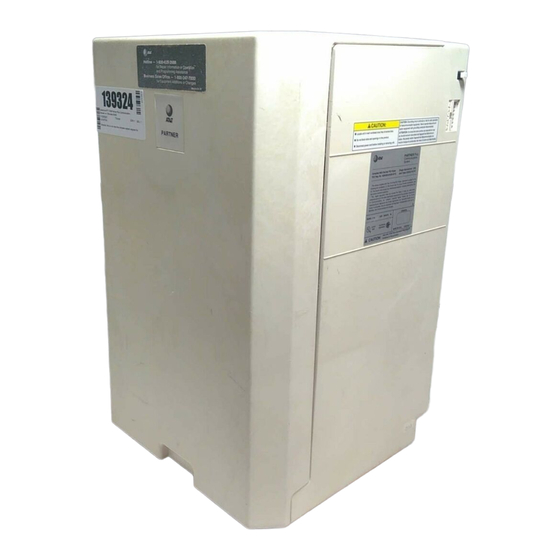
Hardware The PARTNER Plus system’s modular hardware design makes it easy to install and expand. The main system component is the control unit, to which you connect telephones and other equipment. Control Unit The control unit includes: Processor Module. The processor module contains the software that controls the system’s features. -
Page 9: An Example System Setup
An Example System Setup This PARTNER Plus System has 4 outside lines and 8 extensions connected to a variety of PARTNER phones and other equipment. The boldface numbers refer to the following list which gives a brief description of the system’s hardware components. - Page 10 System Components and Specifications 1-3...
-
Page 11: Specifications
Specifications Table 1-1 Technical and Environmental Specifications Capacities System 206 Module Extension Jack 8 outside lines via line jacks on 2 outside lines Maximum 2 devices per exten- four 206 modules 6 extensions sion jack, total REN on jack not 24 extensions via extension jacks to exceed 2* (2 devices require on four 206 modules... - Page 12 Table 1-1 Technical and Environmental Specifications (cont.) 90-130 VAC, 50-60 Hz, 3-prong outlet separate ground, separately fused at 15 amps Electrical Outlet must not be controlled by an on/off switch Requirements Grounding to comply with Underwriters Laboratories (UL) 1459: A. An insulated grounding conductor that is not smaller in size and equivalent in insulation material and thickness to the grounded and ungrounded branch circuit supply conductors, except that it is green with or without one or more yellow stripes, is to be installed as part of the circuit that supplies the pro- duct or system.
-
Page 13: Installing The Hardware
Installing the Hardware... -
Page 14: General Guidelines
General Guidelines Instructions for installing the control unit, telephones, and other equipment are on the following pages (figures 2-1 to 2-3). Before you begin, please note the following guidelines: Using the System Planner is essential for knowing where phones and other equipment are to be installed, and how the system and phones are to be programmed. -
Page 15: Installing The Control Unit
Installing the Control Unit CAUTION: To prevent electrostatic discharge, overheat- TEST THE SYSTEM ing, or other damage, environmental and electrical condi- Connect the AC power cord to the power jack on the top right tions must meet the specifications on p. 1-4. rear of the backplane. - Page 16 Installing the Hardware 2-3...
-
Page 17: Installing Telephones And Other Equipment
Installing Telephones and Other Equipment CAUTION: PARTNER phones must be connected with a Test the outside line connection. I-M the handset and press an 2-pair telephone wire. Other equipment must be connected outside line button. You should hear an outside dial tone. If not, with a 1-pair mounting cord (AT&T D2R mounting cords see chapter 8, in the System Manager’s Guide (“Phone Has recommended). - Page 18 Test a telephone by lifting the handset. You should hear a WALL MOUNTING A PARTNER TELEPHONE dial tone, indicating a good connection on the line. If you WARNING: Do not attempt to unscrew the base from the don’t, see chapter 8, in the System Manager’s Guide, phone.
-
Page 19: Removing/Replacing Modules
Removing/Replacing Modules Removing a Module To remove a processor or 206 module: 1. Disconnect the AC power cord from the wall outlet. 2. Remove the control unit cover by sliding it directly off the backplane. 3. Grasp the front top of the module with one hand while holding down the locking tab at the base of the module with the other hand. -
Page 20: System Programming
System Programming... - Page 21 Alphabetic List of Procedures Abbreviated Ringing 3-16 Allowed List Assignment 3-24 Allowed Phone Number Lists 3-24 Automatic Privacy 3-15 3-26 Calling Group Extensions 3-17 Copy Settings Dial Mode Disallowed List Assignment 3-22 Disallowed Phone Number Lists 3-20 Display Language 3-14 Doorphone 1 Extension 3-32 3-32...
-
Page 22: Overview
Overview This chapter provides instructions for programming your system. Your PARTNER Plus system was programmed at the factory so that it works when installed. However, the needs of your business may require that you change some or all of the factory settings. System programming allows you to change these factory settings. - Page 23 Figure 3-1 Programming Overlay 3-2 System Programming...
-
Page 24: General Instructions
General Instructions Programming the PARTNER Plus system requires no complicated steps or intensive training. By following the detailed instructions given in the rest of this chapter, you can quickly change system settings. As you become familiar with programming, use the Programming Quick Reference on the inside back cover of this guide for procedure codes and settings. -
Page 25: Programming Procedures
Programming Procedures System Date Code: #101 If your system has been previ- Description: The month, day, and year that appears on PARTNER display ously programmed, the displays phones may differ. Valid Entries: Any date Programming Steps: 1. Press [ Feature ] [ 0 ] [ 0 ] [ System Program ] [ System Program ] [ # ] [ 1 ] [ 0 ] [ 1 ] . display reads: System Date Data 010100... -
Page 26: Number Of Lines
System Time Code: #103 Description: The time, in 24-hour military-style notation Valid Entries: Any time Even though you enter the time in Programming Notes: Enter the time in 24-hour notation, commonly known as 24-hour notation, it appears on military time. In this scheme, the hours of the day are 0000 (12 midnight) to display phones as a.m. -
Page 27: Pbx Dial-Out Code
Transfer Return Code: #105 Rings Description: Defines the number of times an extension should ring with a transferred call before the call returns to the originating extension. Valid Entries: 0 (transferred calls not returned to originating extension) 1 through 9 Considerations: If you have a fax machine or an answering machine connected to the system, set this number greater than the number of rings these devices wait before answering. -
Page 28: Recall Timer Duration
Waiting. Change the factory setting of the recall timer only under three conditions: If your PARTNER Plus system is connected to Centrex, set the recall timer to 800 milliseconds (msec) by entering [ 3 ] [ 2 ]. If your PARTNER Plus system is connected to a PBX or Centrex and Recall drops calls, shorten the time. -
Page 29: Outside Conference
Rotary Dialing Code: #108 Time out Description: If you have any rotary lines and are having trouble calling out on standard touch-tone phones, use this procedure to change the length of the Rotary Dialing Timeout. For example, if users dial slowly and calls are not com- pleted or are connected to wrong numbers, lengthen the timeout. -
Page 30: Dial Mode
Dial Mode Code: #201 Description: Identifies each outside line as either touch-tone or rotary. Valid Entries: 1 = Touch-tone line 2 = Rotary line Considerations: If you are using touch-tone phones on rotary lines, you may need to adjust the Rotary Dialing Timeout (#108). Programming Steps: 1. - Page 31 Line Type Code: #202 Description: Identifies each outside line as being connected to the local tele- phone company or to a PBX or a Centrex system. See appendix A for more information on programming for PBX or Centrex. Valid Entries: 1 = CO (local telephone company line) 2 = PBX or Centrex line Considerations:...
-
Page 32: Hold Disconnect Time
Description: When a caller on hold hangs up, the local telephone company may send a special signal to the PARTNER Plus system to free the line. There are two possible signals: a long signal (450 milliseconds) used by most tele- phone companies, or a short signal (50 milliseconds) used by a few telephone companies. -
Page 33: Line Assignment
Line Assignment Code: #301 Description: Use this procedure to change the line assignments on specific extensions. These changes include adding lines, deleting lines, and setting the order of the lines on a PARTNER phone’s line buttons. Valid Entries: 1 = Assigned 2 = Not assigned Hotline and doorphone exten- Considerations: Use this procedure to fine tune the number of lines assigned to... - Page 34 No restriction (all calls permitted on that line) most extreme way to restrict dial- Out only (can only make outside calls, not receive them, ing on the PARTNER Plus sys- on that line) tem. For example, an extension In only (can only receive calls, not make them, on that with a the set to "in only”...
-
Page 35: Display Language
Display Language Code: #303 Description: Sets the language on the display of a PARTNER display phone. The language is set for each extension, so phones on the same PARTNER sys- tem can display different languages. Valid Entries: 1 = English 2 = Spanish 3 = French If you change the language for... -
Page 36: Automatic Privacy
Automatic Privacy Code: #304 Description: Automatically prevents users with the same lines from joining telephone conversations on a specific extension. This feature is typically used for Valid Entries: 1 = Assigned to extension extensions connected to fax 2 = Not assigned machines and modems, which make and receive data calls that Considerations: A user can override Automatic Privacy with the Privacy feature... -
Page 37: Abbreviated Ringing
Abbreviated Code: #305 Ringing Description: Use this procedure to turn Abbreviated Ringing on or off. When a user is on a call and Abbreviated Ringing is on (the factory setting), an incoming call rings only once. The light next to the line button flashes until Receptionists, and others who the call is answered or the caller hangs up. -
Page 38: Copy Settings
Copy Settings Code: #399 Description: Copies the following settings from any extension to any other extension: #408 Allowed List Assignment #301 Line Assignment #302 Line Use Restriction #501 Pickup Group Extensions #303 Display Language #502 Calling Group Extensions #304 Automatic Privacy #504 Night Service Group #305 Abbreviated Ringing #601 Fax Machine Extensions... -
Page 39: Outgoing Call Restrictions
Outgoing Call Code: #401 Restrictions Description: Restricts the types of calls an extension can make. An extension can be restricted to inside calling only, or to local and inside calling. Outgoing While procedures that restrict Call Restrictions apply to all lines assigned to the extension. The System Pass- dialing are very effective, abso- word (#403), Emergency Phone Number List (#406), Disallowed and Allowed lute protection against misuse... -
Page 40: System Password
0 or 1 plus an area code or a tele- ways: phone number preceded only by an area code. Use this procedure to tell the PARTNER Plus system which method your phone company uses. Valid Entries: 1 = 0 or 1 plus the area code... -
Page 41: Disallowed Phone Number Lists
Disallowed Code: #404 Phone Number Description: Specifies telephone numbers that users cannot dial. For example, Lists you may want to prevent calls to a specific telephone number or to categories of numbers such as calls to 976 numbers. Use this procedure to create up to four lists of up to 10 telephone numbers each. - Page 42 Programming Notes: To program telephone numbers, dial the number as you would normally. You can also use the "wildcard” character to stand for any digit in a phone number. For example, if you want to prevent users from making calls to area codes 202 and 212, you could enter each area code separately or com- bine them in one entry using the wildcard to stand for the middle digit.
-
Page 43: Disallowed List Assignment
Disallowed List Code: #405 Assignment Description: After creating Disallowed Phone Number Lists (#404), use this procedure to assign them to specific extensions. For example, you can assign list 1 to extensions 27 and 28, and list 2 to extension 28 only. Valid Entries: 1 = Assigned to extension 2 = Not assigned to extension... -
Page 44: Emergency Phone Number List
Emergency Code: #406 Phone Number Description: Specifies emergency telephone numbers, such as “911,” that can List be dialed from any extension regardless of other dialing restrictions, except Line Use Restriction (#302). See appendix B for a summary of Valid Entries: 10 telephone numbers, 1 to 12 digits each dialing restrictions. -
Page 45: Allowed List Assignment
Allowed Code: #407 Phone Number Description: Specifies telephone numbers that users can dial regardless of Lists other dialing restrictions. For example, even though you restricted all “976” dial- ing through Disallowed Phone Number Lists (#404), you can permit calls to the 976 weather number by entering that number in an allowed list. -
Page 46: Pickup Group Extensions
Pickup Group Code: #501 Extensions Description: Identifies the extensions in the Pickup Group-the group of extensions whose outside calls can be answered by any extension on the sys- tem. When an outside call rings at an extension in the Pickup Group, any other extension on the system can answer the ringing line by pressing [ Intercom ] [ 6 ] [ 6 ] . -
Page 47: Calling Group Extensions
Calling Group Code: #502 Extensions Description: Identifies the extensions in the Calling Group-the group of exten- sions that can be called at the same time. Any user on the system can ring all the phones in the Calling Group by dialing [ Intercom ]. Users can also voice signal the phones in the Calling Group by dialing [ Intercom ] [ * ] [ 7 ] [ 1 ]. -
Page 48: Night Service Button
Night Service Button Code: #503 Description: To use the Night Service feature, you must program it onto the PARTNER display phone at extension 10. This procedure automatically assigns Night Service to the second programmable feature button with lights: Night Service is useful if you want To turn Night Service on and off, simply press this button. -
Page 49: Night Service Group
Night Service Group Code: #504 Description: Identifies the extensions in the Night Service Group. When Night Service is on and a call comes in, all extensions in the Night Service Group ring immediately. In addition, restricted Night Service (when the system has a pass- word) limits the Night Service Group extensions to dialing only numbers on the Emergency Phone Number List (#403) and Marked System Speed Dial Numbers (p. -
Page 50: Fax Machine Extensions
Fax Machine Code: #601 Extensions Description: If you have a fax machine connected to the system and want to monitor its status with a Fax Management button (see the System Manager’s Guide, chapter 7), use this procedure to identify the fax extension. Valid Entries: 1 = Extension assigned 2 = Extension not assigned... -
Page 51: Music On Hold
Music On Hold Code: #602 Description: Activates or deactivates the Music-on-Hold jack on the processor module. To provide music or taped messages to callers on hold, the Music-on- Hold jack must be active and an audio source attached to the jack. Valid Entries: 1 = Active 2 = Not active... -
Page 52: Hotline
Hotline Code: #603 Description: Identifies the “hotline” extension and the extension it automatically rings (the “alert” extension). When someone lifts the handset of the hotline tele- phone, the alert extension rings. You can set up several hotline and alert exten- sion pairs. -
Page 53: Doorphone 1 Extension
Doorphone 1 Extension Code: #604 Description: You can connect up to two doorphones to the PARTNER Plus system. Each doorphone can ring up to five other “alert” extensions. Use this A doorphone consists of a speaker and a button. It is usu- procedure to identify the extension to which the first doorphone is connected. -
Page 54: Doorphone Alert Extensions
Doorphone Code: #606 Alert Description: Identifies the extension or extensions that ring when someone Extensions presses the button on a doorphone. Each doorphone can have up to five alert extensions. The doorphones can have five individual alert extensions or they can share alert extensions. -
Page 55: Systemreset—Programmingsaved
Dial Description: You can program a list of up to 60 frequently dialed numbers into the PARTNER Plus system. Anyone on the system can then dial these numbers Numbers by pressing [ Feature ] and the 2-digit code you assign the number during programming. - Page 56 Programming Steps: Press [ Feature ] [ ] [ 0 ] . The display reads: PROGRAM EXT 10 2. Enter the 2-digit code you want to assign the phone number by pressing [ Feature ] and 2 digits between 20 and 79. For example, to assign code 20, press [ Feature ] [ 2 ] [ 0 ] .
- Page 57 Table 3-1 Special Dialing Functions Function Button Display Description and Example Pause Inserts a 1.5-second pause in the dialing sequence to wait Hold for a response, such as a dial tone or computer voice mes- sage. Example: To call an answering machine at 555-0529, wait 4.5 seconds, then dial 321 to retrieve messages, enter [ 5 ] [ 5 ] [ 5 ] [ 0 ] [5 ] [ 2 ] [ 9 ] [ Hold ] [ Hold ] [ 3 ] [ 2 ] [ 1 ].
-
Page 58: Centralized Telephone Programming
Centralized Telephone Programming... - Page 59 Alphabetic List of Procedures Auto Dial Numbers Automatic Line Selection 4-12 Call Pickup 4-13 Calling Group Conference Drop Do Not Disturb Exclusive Hold Last Number Redial Line Ringing Options 4-13 Loudspeaker Paging 4-11 Message Light Off 4-11 Message Light Speed Numbers Personal Dial...
-
Page 60: Overview
Overview PARTNER telephones are ready to use when installed. However, just as the system can be programmed to meet your business’s needs, the phones can be programmed to meet users’ needs. Individual users can program their own phones. In addition, you can program any phone on the system from extension 10. - Page 61 PARTNER Display and PARTNER 12-Button PARTNER 6-Button Phone Phones Figure 4-1 Buttons and Labeling Sheets for PARTNER Phones 4-2 Centralized Telephone Programming...
-
Page 62: Programming Procedures
Programming Procedures Automatic Line Description: When a user lifts the handset to make a call without first pressing a line button, the system connects him or her to a line, as determined by the Selection Automatic Line Selection. The factory set order connects the user to the first For example, lines 1 and 2 are available outside line assigned to the extension, in numerical order. - Page 63 Line Ringing Description: Each outside line assigned to an extension can ring immediately, be delayed 20 seconds before ringing, or not ring at all. “Delayed ring” is useful Options for backup coverage on shared lines, such as for secretaries who cover each otther's lines.
- Page 64 Personal Speed Dial Description: You can program up to 20 frequently dialed numbers for each extension. The user can then dial these numbers by pressing [ Feature ] and the Numbers 2-digit code you assign the number during programming. Personal Speed Dial numbers do not override other restrictions assigned to an extension.
-
Page 65: Auto Dial Numbers
Auto Dial Numbers Description: Use this procedure to program outside telephone numbers or other extension numbers onto buttons for one-touch dialing. Auto Dial numbers do not override the dialing restrictions for the extension. Considerations: You cannot program System and Personal Speed Dial codes as Auto Dial Programming an Auto Dial exten- numbers. - Page 66 Do Not Disturb Feature Code: Description: Prevents a telephone from ringing. When Do Not Disturb is on, outside callers hear ringing while inside callers hear a busy signal. By program- ming this feature on a button, the user can turn Do Not Disturb on and off with one touch.
- Page 67 Recall Feature Code: 03 Description: Sends a timed switchhook flash over the telephone line. The user may need to send a recall signal to use certain Centrex or PBX features, such as Call Waiting. By programming this feature on a button, the user can send a recall signal with one touch.
- Page 68 Last Number Redial Feature Code: 05 Description: Redials the last outside number dialed at the extension (maximum 20 digits per phone number). By programming this feature on a button, the user can redial the number with one touch. System Speed Dial numbers cannot be saved for redialing.
- Page 69 Privacy Feature Code: Description: Prevents other users with the same line from joining telephone conversations. By programming this feature on a button, the user can turn Privacy on and off with one touch. Considerations: If an extension has Automatic Privacy the user can (#304), turn it off and on with Privacy.
- Page 70 Message Light On Feature Code: 09 Description: Alerts another extension that there is a message for it by turning on the Message light at that extension. By programming this feature on a button, the user can turn on the message light at a PARTNER phone by pressing the button and dialing the extension.
-
Page 71: Call Pickup
Call Pickup Description: Enables the user to answer any call ringing on a specific exten- sion. By programming this feature on a button, the user can pick up a call on This feature is useful for that extension with one touch. oifficemates who agree to answer Programming Steps each other’s calls. -
Page 72: Calling Group
Loudspeaker Description: If the system has a loudspeaker paging system, this feature Paging activates it. By programming this feature on a button, the user can activate the loudspeaker with one touch. Programming Steps: 1. Press [ Feature ] [ 0 ] [ 0 ] [ System Program ] [ System Program ] [ Central Tel Prog ]. The display reads: CENTRAL TEL PROG Extension:... - Page 73 Programming for Operation Behind PBX or Centrex If you are connecting your PARTNER Plus system to a PBX (Private Branch Exchange) or Centrex system, instead of directly to local telephone company lines, there are two ways to program the system. Your choice depends on what kinds of calls your users tend to make.
- Page 74 [ 9 ] [ H o l d ] [ H o l d ] [ 5 ] [ 5 ] [ 5 ] [ 1 ] [ 2 ] [ 1 ] [ 2 ]. To program a PBX/Centrex extension number or a PARTNER Plus exten- sion number, do not enter [ 9 ] [ Hold ] [ Hold ] before the number.
- Page 75 Dialing Restrictions Summary The PARTNER Plus system includes several ways to restrict dialing from individual extensions. This appendix discusses the dialing restrictions and ways to override the restrictions. The system programming procedures necessary to set the restrictions are also included.
- Page 76 Outside Dialing Allowed When an extension is allowed access to an outside line, several dialing restric- tions can apply. First, regardless of other restrictions, some types of calls are always allowed. Second, you can restrict dialing after normal business hours through Night Service.
- Page 77 #401—Outgoing Call Restrictions. Using this procedure, you set one of three dialing restrictions for each extension: “No restriction” allows long distance, local, and inside calling. “Local only” allows local and inside calling only (make sure the Toll Call Prefix is set properly, #402). “Inside only”...
- Page 78 FCC Information Federal Communications Commission (FCC) Warning Statement This equipment has been tested and found to comply with the limits for a Class A digital device, pursuant to Part 15 of FCC rules. These limits are designed to provide reasonable protection against harmful interference when the equipment is operated in a commercial environment.
- Page 79 You must also notify your local telephone company if and when this equip- ment is permanently disconnected from the line(s). Repair Instructions: If you experience trouble because your equipment is malfunctioning, the FCC requires that the equipment not be used and that it be disconnected from the network until the problem has been corrected.
- Page 80 Index 206 module, 1-1, 1-2, 1-3 Date, System (#101), 3-4 267F2 bridging adapter, 1-2, 1-3, 2-5 Day, System (#102), 3-4 Delayed ring, 4-4 Desk mounting a PARTNER phone, 2-4 Dial Mode (#201), 3-9 Dialing restrictions, summary, B-1 to B-3 Direct station status, see Auto Dial numbers Dial-out code (PBX/Centrex), 3-6 Abbreviated Ringing (#305), 3-16 Dimensions, 1-4...
- Page 81 Line cords, connecting, 2-2, 2-3 Group, Calling, 3-26, 4-13 Group, Night Service, 3-28 Line jacks, 1-2, 1-3 Line Ringing Options, 4-4 Group, Pickup, 3-25, 4-12 Line Selection, Automatic, 4-3 Guidelines for installation, 2-1 Line Type (#202), 3-10 Line Use Restriction (#302), 3-13, B-1 Lines in system, 3-5, 3-9, 3-10, 3-12 Lines, assigning lines to extensions, 3-12, B-1 Lines, Number of (#104), 3-5...
- Page 82 Redial, Last Number, 4-9 Redial, Save Number, 4-8 Removing modules, 2-6 Replacing modules, 2-6 Resetting the system, 3-34 One-touch transfer, see Auto Dial Numbers Restrictions, dialing, B-1 to B-3 Outgoing Call Restrictions (#401 ), 3-18, B-3 Restrictions, Outgoing Call (#401), 3-18, B-3 Outside Conference restriction (#109), 3-8 Ringer Equivalence Number (REN), 1-4, 1-5 Overlay, programming, 3-1 to 3-2...
- Page 83 Telephones installation, 2-4 to 2-5 programming centrally, 4-1 to 4-13 Time, System (#103), 3-5 Toll Call Prefix (#402), 3-19 Touch-Tone Enable programming feature on a button, 4-10 programming function in phone number, 3-36 Touch-tone lines, 3-9 Transfer Return Rings (#105), 3-6 Wall mounting a PARTNER phone, 2-5 Weights, 1-4 Wires, connecting, 2-2 to 2-3...
-
Page 84: Message Light Off
SYSTEM SPEED DIAL NUMBERS (p. 3-34) P r o g r a m m i n g PRESS [ Feature ] to enter system program mode Quick Reference PRESS [ Feature ] followed by a 2-digit code (20 to 79) DIAL the telephone number (up to 20 digits and special functions) Centralized Telephone To include special functions in the telephone number... - Page 85 SYSTEM PROGRAMMING TO ENTER PROGRAM MODE TO RETURN DATA TO FACTORY SETTlNG: TO GO TO A PARTICULAR PROCEDURE DIAL ITS 3-DIGIT CODE Press [ Feature ] [ 0 ] [ 0 ] [ System Program ] [ System Program ] Press [ Remove ] Example: [ # ] [ 1 ] [ 0 ] [ 1 ] TO CYCLE THROUGH THE PROCEDURES...
- Page 86 SYSTEM RESET- PROGRAMMING SAVED (p. 3-34) DIAL #728 CAUTION: Disconnects active calls. OPTIONAL EQUIPMENT RESTRICTIONS GROUPS FAX MACHINE EXTENSIONS* OUTGOING CALL RESTRlCTI0NS PICKUP GROUP EXTENSIONS (pp. 1-2 and 3-29) (p. 325) (p. 3-18) DIAL #601 DIAL #501 DIAL #401 DIAL an extension number DIAL an extexsion number DIAL an extension number DIAL...
- Page 87 Issue 2, October 1990 Comcode 106430184 999-506-141 Graphics © AT&T 1988...