
Related Manuals for Mercury TDI 3.0L


Summary of Contents for Mercury TDI 3.0L
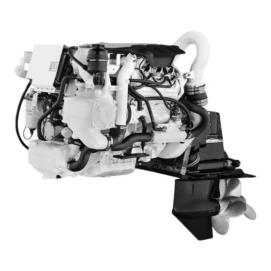
- Page 1 TDI 3.0L Diesel Engine Sterndrive Models OPE RA TIO N & M A I NTE NA NC E M AN U AL...
- Page 3 State of California to cause cancer and birth defects or other reproductive harm. For more information go to www.P65Warnings.ca.gov. The serial numbers are the manufacturer’s keys to numerous engineering details that apply to your Mercury Marine power package. When contacting Mercury Marine about service, always specify model and serial numbers.
- Page 4 At Mercury Marine every engine is operated and tested before it is boxed for shipment to make sure that the product is ready for use. In addition, certain Mercury Marine products are tested in a controlled and monitored environment, for up to 10 hours of engine run time, in order to verify and make a record of compliance with applicable standards and regulations.
-
Page 5: Table Of Contents
TABLE OF CONTENTS Section 1 - Getting to Know Your Power Package Engine Component List.............. 2 Switches................9 3.0 Liter TDI Front View Components........ 2 Emergency Stop Switch............ 10 3.0 Liter TDI Starboard View Components......2 Lanyard Stop Switch............10 3.0 Liter TDI Port View Components........ - Page 6 Diesel Fuel in Cold Weather........... 34 Bravo Sterndrive Fluid Specifications—Diesel....36 Antifreeze/Coolant..............34 Power Steering and Power Trim Fluids......36 Engine Oil ................35 Approved Power Steering Fluids......... 36 Engine Specifications............. 35 Approved Power Trim Fluids........36 Fluid Specifications..............36 Approved Paints..............
- Page 7 Excessive Engine Temperature........95 Operate)................97 Insufficient Engine Temperature........96 Section 7 - Customer Assistance Information Owner Service Assistance............. 100 Contact Information for Mercury Marine Customer Service Local Repair Service............100 ..................101 Service Away From Home..........100 Customer Service Literature..........101 Stolen Power Package.............
- Page 8 Page iv 90-8M0145546 MAY 2018...
- Page 9 Section 1 - Getting to Know Your Power Package Section 1 - Getting to Know Your Power Package Table of Contents Engine Component List............2 Switches................9 3.0 Liter TDI Front View Components......2 Emergency Stop Switch..........10 3.0 Liter TDI Starboard View Components...... 2 Lanyard Stop Switch............
-
Page 10: Engine Component List
Section 1 - Getting to Know Your Power Package Engine Component List 3.0 Liter TDI Front View Components Gear lubrication monitor Engine control module cover Engine oil dipstick Engine coolant expansion tank Power steering oil reservoir Charge air cooler (intercooler) Sacrificial anode Seawater inlet connection Seawater pump... -
Page 11: 3.0 Liter Tdi Port View Components
Engine coolant expansion tank Engine control module cover 52239 Features and Controls TDI 3.0 Liter Engine Features The Mercury Diesel 3.0 Liter 6‑cylinder engine has the following features: • Four‑stroke diesel engine • Common‑rail direct injection • 6 cylinders (90° V angle) •... -
Page 12: Keep The Lanyard Stop Switch And Lanyard Cord In Good Operating Condition
Section 1 - Getting to Know Your Power Package The lanyard cord is usually 122–152 cm (4–5 feet) in length when stretched out, with an element on one end made to be inserted into the switch and a clip on the other end for attaching to the operator's PFD or wrist. The lanyard is coiled to make its at‑rest condition as short as possible to minimize the likelihood of lanyard entanglement with nearby objects. -
Page 13: Instrumentation
Section 1 - Getting to Know Your Power Package Instrumentation VesselView Your power package may be connected to a SmartCraft VesselView multifunction display. VesselView is a comprehensive boat information center that can display information for up to four gasoline or diesel engines. It continuously monitors and reports basic operating data including detailed information such as seawater temperature and depth, trim status, boat speed and steering angle, and the status of fuel, oil, water, and waste tanks. -
Page 14: System Link Digital Gauges
Section 1 - Getting to Know Your Power Package System Link Digital Gauges Some instrumentation packages include gauges that augment the information provided by VesselView and the SmartCraft tachometer and speedometer. The owner and operator should be familiar with all the instruments and their functions on the boat. -
Page 15: Single Engine Trim And Trailer
Section 1 - Getting to Know Your Power Package For best performance trim the sterndrive so that the boat bottom is at a 3–5° angle to the water. 3 - 5 mc79528 Trimming the sterndrive up (out) can: • Generally increase top speed •... -
Page 16: Power Trim And Mercathode Overload Protection
If the fuse burns out, the electrical overload has not been eliminated. Further checks must be made on the electrical system. Contact your Mercury Diesel authorized repair facility. The power trim system is protected from overload by a 110‑amp fuse and a 20‑amp in‑line fuse on the power trim pump. -
Page 17: Engine Guardian System
Section 1 - Getting to Know Your Power Package Intermittent short beeps for six seconds: Indicates a noncritical engine condition. This condition does not require immediate attention. You may continue using your boat, however, depending on the nature of the problem, the engine’s power may be limited by the Engine Guardian system to protect the engine. -
Page 18: Emergency Stop Switch
30 seconds will restart the engine but cause fault codes to be set. Unless you are in a potentially hazardous situation, turn the key switch off and wait at least 30 seconds before restarting the engine or engines. If after restarting, some fault codes are still being displayed, contact your authorized Mercury Diesel repair facility. Lanyard Stop Switch The purpose of a lanyard stop switch is to turn off the engine when the operator moves far enough away from the operator's position (as in accidental ejection from the operator's position) to activate the switch. -
Page 19: Keep The Lanyard Stop Switch And Lanyard Cord In Good Operating Condition
Section 1 - Getting to Know Your Power Package The lanyard cord is usually 122–152 cm (4–5 feet) in length when stretched out, with an element on one end made to be inserted into the switch and a clip on the other end for attaching to the operator's PFD or wrist. The lanyard is coiled to make its at‑rest condition as short as possible to minimize the likelihood of lanyard entanglement with nearby objects. -
Page 20: Remote Control
Forward gear Reverse gear 51014 Digital Throttle and Shift Digital Throttle and Shift (DTS) operating instructions are provided in a separate manual. Refer to Mercury Diesel's SmartCraft and DTS Operator's Manual. Electrical System Overload Protection CAUTION Failure to protect wiring with an appropriate fuse can damage the wiring and start a fire. When installing any accessories, we recommend using a Mercury accessory kit. -
Page 21: Vessel Adapter Assembly (Vaa) Fuse Replacement
Section 1 - Getting to Know Your Power Package The remaining fuses are located in the vessel adapter assembly (refer to your boat owner's manual for location) and on the rear side of the control unit of the individual instrumentation. Engine control module 25‑amp fuse 15‑amp fuse... -
Page 22: Identification
Section 1 - Getting to Know Your Power Package Identification Serial Number Decal Placement Three sets of engine, transom assembly, and sterndrive serial number decal strips are provided with each power package. One set should be used for each of the following: •... -
Page 23: Bravo Sterndrive Serial Number And Identification
Section 1 - Getting to Know Your Power Package Bravo Sterndrive Serial Number and Identification The Bravo sterndrive serial number, gear ratio, model number, and bar code are embedded in the ground plate on the port side of the sterndrive. 33533 Bravo sterndrive information on ground plate The serial number is also stamped as a permanent reference on the sterndrive casting inside the back cover. -
Page 24: Seacore Equipped Drives
Section 1 - Getting to Know Your Power Package The serial number is also stamped on the gimbal housing. This is used as a permanent reference for Mercury Diesel authorized repair facilities. Gimbal housing with serial number stamping Transom assembly serial... -
Page 25: Emissions Information
Boatbuilders and dealers may not remove the label or the part it is affixed to before sale. If modifications are necessary, contact Mercury Diesel about the availability of replacement decals before proceeding. - Page 26 Section 1 - Getting to Know Your Power Package Notes: Page 18 90-8M0145546 MAY 2018...
- Page 27 Section 2 - On The Water Section 2 - On The Water Table of Contents Safe Boating Recommendations.......... 20 While Boat Is Stationary ........27 Carbon Monoxide Exposure..........21 High Speed and High Performance....... 27 Be Alert To Carbon Monoxide Poisoning ..... 21 Passenger Safety in Pontoon Boats and Deck Boats..
-
Page 28: Safe Boating Recommendations
Most boats are rated and certified for maximum load (weight) capacities (refer to your boat's capacity plate). Know your boat's operating and loading limitations. Know if your boat will float if it is full of water. When in doubt, contact your authorized Mercury Marine dealer or the boat manufacturer. Ensure that everyone in the boat is properly seated. -
Page 29: Carbon Monoxide Exposure
Section 2 - On The Water Be alert. • The operator of the boat is responsible by law to maintain a proper lookout by sight and hearing. The operator must have an unobstructed view particularly to the front. No passengers, load, or fishing seats should block the operator's view when the boat is above idle or planing transition speed. -
Page 30: Poor Ventilation
(WOT) at the rated engine RPM. The power package must also be applied in accordance with recommendations indicated in the appropriate applications manual. Use of Mercury Diesel engines in other than the applications indicated by the following information and in the appropriate applications manual requires written approval from an authorized Mercury Diesel application engineer. - Page 31 Section 2 - On The Water EPA Mode Number MODES Cycle 5 DUTY CYCLE Engine speed (percent of WOT) Idle Engine power (percent of total) Time at given mode (percent of total operating time) Chart showing full power operation is limited to a maximum of 1 of 12 hours Mode 1: 1.0 hour (8%) Mode 2: 1.5 hours (13%) Mode 3: 2.0 hours (17%)
-
Page 32: Tdi Operation Chart
Section 2 - On The Water TDI Operation Chart Starting Procedure After Starting While Underway Stopping and Shutdown Observe all gauges and Frequently observe all gauges Open the engine hatch. Air indicator lamps to check the Shift the remote control lever and indicator lamps to monitor out the bilge completely. -
Page 33: Before Starting The Engine
• Check all items listed in the Maintenance Schedule and Operation Chart. • Perform any other necessary checks as indicated by your Mercury Diesel authorized repair facility or specified in your boat owner’s manual. Starting a Cold Engine IMPORTANT: Check the fluid levels before starting the engine. Refer to Maintenance. -
Page 34: Starting A Warm Engine
Check for coolant leaks. Check the coolant hoses and connection pipes of the heat exchanger, fluid coolers, aftercooler, water pump, and drain fittings for leaks. Correct any problems found, or see your Mercury Diesel‑authorized repair facility if you are unable to determine the problem. -
Page 35: Freezing Temperature And Cold Weather Operation
• If operating in arctic temperatures of –29° C (–20° F) or lower, consult your Mercury Diesel authorized repair facility for information about special cold weather equipment and precautions. Refer to Storage for cold weather or extended storage related information. -
Page 36: Passenger Safety In Pontoon Boats And Deck Boats
Section 2 - On The Water Passenger Safety in Pontoon Boats and Deck Boats Whenever the boat is in motion, observe the location of all passengers. Do not allow any passengers to stand or use seats other than those designated for traveling faster than idle speed. A sudden reduction in boat speed, such as plunging into a large wave or wake, a sudden throttle reduction, or a sharp change of boat direction, could throw them over the front of boat. -
Page 37: Impact With Underwater Hazards
After striking a submerged object, stop the engine as soon as possible and inspect the drive system for any broken or loose parts. If damage is present or suspected, the power package should be taken to a Mercury Diesel‑authorized repair facility for a thorough inspection and any necessary repair. -
Page 38: Cavitation
Section 2 - On The Water • Straight and smooth, fore and aft Marine vegetation may accumulate when the boat is docked. This growth must be removed before operation; it may clog water inlets and cause the engine to overheat. Cavitation Cavitation occurs when water flow cannot follow the contour of a fast‑moving underwater object, such as a gear housing or a propeller. -
Page 39: Break-In
End of First Season Checkup At the end of the first season of operation, contact an authorized Mercury Diesel repair facility regarding scheduled maintenance items. If the product is operated on a continuous, or year‑round basis, contact the dealer at the end of the first 100 hours of operation or once yearly, whichever occurs first. - Page 40 Section 2 - On The Water Notes: Page 32 90-8M0145546 MAY 2018...
-
Page 41: Section 3 - Specifications
Section 3 - Specifications Section 3 - Specifications Table of Contents Fuel Requirements............... 34 Engine Fluid Capacity............ 36 Nonferrous Metals and the Fuel System ...... 34 Bravo Sterndrive Fluid Specifications—Diesel....36 Diesel Fuel in Cold Weather..........34 Power Steering and Power Trim Fluids......36 Antifreeze/Coolant.............. -
Page 42: Fuel Requirements
Mercury diesels are required to use Grade No. 2‑D ULSD (ultra‑low sulphur diesel) fuel meeting ASTM Standards D975 (or fuel rated Diesel DIN EN 590), and having a minimum cetane rating of 40. -
Page 43: Engine Oil
Section 3 - Specifications Only premixed coolant should be added to the closed‑cooling system. Additives and inhibitors introduced into acceptable coolant solutions will form a protective film on the internal passages and provide protection against internal cooling system erosion. Do not drain the closed‑cooling section for storage. The closed‑cooling section should be kept filled year‑round with an acceptable antifreeze/coolant solution to avoid rust forming on the internal surfaces. -
Page 44: Fluid Specifications
*Battery manufacturers may rate and test their batteries to different standards. MCA, CCA, Ah, and reserve capacity (RC) are the ratings recognized by Mercury Marine. Manufacturers that use standards different than these, such as equivalent MCA, do not meet Mercury Marine battery requirements. - Page 45 Section 3 - Specifications Description Part Number Mercury Phantom Black 92‑802878Q 1 Mercury Warm Fusion White 8M0094987 90-8M0145546 MAY 2018 Page 37...
- Page 46 Section 3 - Specifications Notes: Page 38 90-8M0145546 MAY 2018...
-
Page 47: Section 4 - Maintenance
Section 4 - Maintenance Section 4 - Maintenance Table of Contents Owner and Operator Responsibilities........40 Draining ................ 58 Dealer Responsibilities............40 Replacing ..............58 Cleaning Care Recommendation......... 40 Filling ................59 Do Not Use Caustic Cleaning Chemicals...... 40 Purging the Fuel System............59 Cleaning Gauges............ -
Page 48: Owner And Operator Responsibilities
It is the operator's responsibility to perform all safety checks, to ensure that all lubrication and maintenance instructions are complied with for safe operation, and to return the unit to a Mercury Diesel–authorized repair facility for a periodic checkup. Normal maintenance service and replacement parts are the responsibility of the owner or operator and are not covered by the terms of the warranty. -
Page 49: Replacement Parts Warning
IMPORTANT: Refer to Maintenance Schedule for a complete listing of all scheduled maintenance to be performed. Some tasks can be done by the owner or operator, while others should be performed by an authorized Mercury Diesel repair facility. Before attempting maintenance or repair procedures not covered in this manual, we recommended that you purchase the appropriate Mercury Diesel service manual and read it thoroughly. -
Page 50: Inspection
Check for loose, damaged, or missing parts, hoses, and clamps; tighten or replace as necessary. Check electrical connections and leads for damage. Remove and inspect the propeller. If it is badly nicked, bent, or cracked, contact your Mercury Diesel–authorized repair facility. -
Page 51: Every 200 Hours Or Annually (Whichever Occurs First)
Section 4 - Maintenance • Inspect the sterndrive U‑joints and lubricate the splines. Inspect the bellows, the exhaust tube, and check the clamps for tightness. • Inspect the gimbal bearing and lubricate the engine coupler every 50 hours if operated at idle for prolonged periods of time. •... -
Page 52: Adding Engine Oil
Section 4 - Maintenance Remove the dipstick, wipe it clean, and install it into the dipstick tube. Verify that the dipstick is completely inserted into the tube. 52253 Remove the dipstick and observe the oil level. The oil level must be between the marks on the dipstick. If necessary, add oil. -
Page 53: Changing The Oil Filter
Section 4 - Maintenance Add the specified oil to bring the oil level up to, but not over, the maximum mark on the dipstick. No oil required Oil may be added but not to exceed range "a" Oil must be added but not to exceed range "a" 50584 NOTE: If the engine will be running for an extended period of time (10–12 hours), the oil level must be in the middle of the MIN and MAX markings indicated on the dipstick. -
Page 54: Sterndrive Gear Lube
Section 4 - Maintenance Apply clean oil to the new sealing O‑rings. Filter cover O‑ring Oil filter element Pin with O‑ring 50601 Install the new oil filter element into the filter housing. IMPORTANT: When installing the oil filter element, ensure that the pin on the lower end of the filter element is aligned with the hole in the housing. -
Page 55: Filling
IMPORTANT: If more than 59 ml (2 fl oz) of High Performance Gear Lube is required to fill the gear lube monitor, a seal may be leaking. Damage to the sterndrive may occur due to lack of lubrication. Contact your Mercury Diesel–authorized repair facility. -
Page 56: Changing
Section 4 - Maintenance Changing Remove the gear lube monitor from the bracket. Gear lube monitor bracket Gear lube monitor and cap Retaining strap 5500 Empty the contents of the gear lube monitor into a suitable container. Install the gear lube monitor in the bracket. Bravo One X Models: Remove the propeller. - Page 57 IMPORTANT: If any water drains from the fill and drain plug hole, or if the gear lube appears milky, the sterndrive is leaking and should be checked immediately by your Mercury Diesel–authorized repair facility. Lower the sterndrive so that the propeller shaft is level.
-
Page 58: Power Trim Fluid
Section 4 - Maintenance 14. Quickly install the sealing washer and the fill and drain plug. Tighten the plug to the specified torque. mc79506-1 14621 All Bravo models shown Fill and drain plug Sealing washer 19777 Description lb‑in lb‑ft Fill and drain plug —... -
Page 59: Filling
Section 4 - Maintenance Tube Ref No. Description Where Used Part No. Power Trim and Steering Fluid Power trim pump 92-858074K01 Filling If the fluid level is below the "MIN" line, the specified fluid must be added. Remove the fill cap from the reservoir. NOTE: Fill cap is vented. -
Page 60: Filling
Remove the fill cap and dipstick from the fluid reservoir and observe the level. 52257 IMPORTANT: If fluid is not visible in the fluid reservoir, see your Mercury Diesel authorized repair facility. Filling Remove the fill cap/dipstick and wipe it with a clean cloth. -
Page 61: Checking
50656 The pressure cap maintains pressure on the cooling system and may not be holding pressure properly. To have the cap tested, contact your Mercury Diesel authorized repair facility. Refer to Filling and add the specified coolant as necessary. IMPORTANT: When installing the pressure cap, be sure to tighten it securely until it clicks to prevent coolant loss. -
Page 62: Changing
Section 4 - Maintenance If the coolant is low in the coolant expansion tank, add the specified coolant as necessary to bring the level between the minimum mark and the maximum mark. Pressure cap Maximum mark Minimum mark 52258 Description Capacity Part Number Extended Life Antifreeze/Coolant... -
Page 63: Filling The Closed-Cooling System
Closed‑cooling system drain screw Seawater system drain screw 50672 If required, clean the closed‑cooling system. See your Mercury Diesel authorized repair facility. Fill the system with the specified coolant. Refer to Filling the Closed‑Cooling System. Filling the Closed‑Cooling System IMPORTANT: Use only the specified coolant. -
Page 64: Air Filter Cleaning
Section 4 - Maintenance Inspect the O‑ring in the pressure cap for damage and replace if necessary. Pressure cap Over pressure valve O‑ring 50656 10. Install the pressure cap after the engine has reached normal operating temperature (with the thermostat fully open) and the coolant level remains constant. -
Page 65: Installation
Section 4 - Maintenance Use compressed air to blow out the filter from the inside towards the outside. Do not exceed the air pressure specification. Air filter Compressed air nozzle 50675 Air Filter Cleaning Maximum air pressure 2.0 bar (29 psi) IMPORTANT: Do not use petroleum products for cleaning the air filter as the filter element may be damaged. -
Page 66: Draining
Section 4 - Maintenance NOTICE Water entering the fuel injection system will cause corrosion and rusting of the injectors and other components, disabling the fuel injection system. Check daily for water in the water‑separating fuel filter and have the engine inspected immediately if there is evidence of water in the fuel system. -
Page 67: Filling
13. Connect the battery cables. 14. Start and operate the engine. Check the filter connection for fuel leaks. If leaks exist, recheck filter installation. If leaks continue, stop the engine immediately and contact your Mercury Diesel authorized repair facility. Filling A plunger‑type of primer pump is located on the fuel filter bracket and is used to:... -
Page 68: Fuel System
Seawater Pump Impeller Inspection The seawater pump impeller must be inspected (and replaced, if necessary) at the interval specified by the maintenance schedule. It is recommended this task be performed at a Mercury Diesel–authorized repair facility. Close the seacock. Page 60... -
Page 69: Sterndrive Water Inlets Check
Section 4 - Maintenance Remove the four screws on the front side of the seawater pump and remove the cover. Discard the O‑ring. 50717 Seawater pump cover screws Mark the direction of rotation of the impeller and remove the protective cap from the middle of the impeller. Seawater pump Impeller Protective cap... -
Page 70: Flushing And Draining The Seawater System
Section 4 - Maintenance Remove the wire from the sterndrive and retain for periodic water inlet checks. Dual water pickup water inlets Side pickup water inlets 22495 Flushing and Draining the Seawater System Close the seacock. Open and clean the seawater filter. Fill the seawater filter with fresh water and operate the engine at idle. -
Page 71: Checking The Seawater Pickups
Section 4 - Maintenance Checking the Seawater Pickups Verify the water inlet holes for the seawater pickup are clean and unobstructed. 16776 Typical through-the-hull seawater pickup Typical through-the-transom seawater pickup Water inlet holes Cleaning the Seawater Strainer, if Equipped NOTICE An open seawater strainer or seacock during some service or maintenance procedures can introduce water into the boat, causing damage or sinking the boat. -
Page 72: Corrosion Protection
The electrical current flow causes the metal that is most chemically active, or anodic, to erode. This is known as galvanic corrosion. For more information contact your authorized Mercury MerCruiser dealer. Maintaining Ground Circuit Continuity The transom assembly and sterndrive are equipped with a ground wire circuit to ensure good electrical continuity between the engine, transom assembly, and sterndrive components. - Page 73 Section 4 - Maintenance Models equipped with a transom harness must connect its ground wire to the grounding screw on the gimbal housing. Gimbal housing grounding screw Transom harness ground wire to engine harness Transom plate grounding stud and nut Grounding wire gimbal housing to transom plate 37462...
-
Page 74: Engine Corrosion Protection Components
Section 4 - Maintenance 37513 37632 Ground washer shown inside anode cavity Bravo sterndrive shown of Bravo Three gear housing, other models Sterndrive similar Ground washer Ground plate (later model) U‑joint bellows ground clip Exhaust bellows ground clip 59936 Engine Corrosion Protection Components The engine is equipped with a sacrificial anode located on the intercooler end cover to assist in protecting the engine and the seawater cooling system from corrosion. -
Page 75: Cleaning And Inspection
Section 4 - Maintenance Remove the anode assembly. Intercooler Anode plug Anode length 20 mm (0.79 in.) 54639 Cleaning and Inspection Inspection and replacement interval will vary according to the condition of the seawater and the mode of engine operation. NOTE: Use sandpaper, fiber brush, or cleaning pad, remove the deposits from the surface of the anode before trying to determine the amount of erosion. -
Page 76: Sterndrive Corrosion Protection Components
Section 4 - Maintenance Install the anode assembly with the washer into the intercooler end cover and tighten securely. Anode 50781 Unplug and connect the seawater inlet hose, or open the seacock if equipped. NOTICE Without sufficient cooling water, the engine, the water pump, and other components will overheat and suffer damage. Provide a sufficient supply of water to the water inlets during operation. - Page 77 Section 4 - Maintenance Dual sterndrive Anode (Alpha models), MerCathode (Bravo models) Ventilation plate anode Trim cylinder anodes Bearing carrier anodes Gearcase anodic plate Anode kit on hull (if equipped) 35213 NOTICE Washing the MerCathode assembly can damage components and lead to rapid corrosion. Do not use any cleaning equipment such as brushes or high‑pressure washers to clean the MerCathode assembly.
- Page 78 Section 4 - Maintenance Description Location Figure Alpha sterndrive Mounted on the underside of the gimbal housing. gimbal housing anode 53380 Bravo sterndrive Mounted on the underside of the lower gearcase. gearcase anode plate 20336 Alpha and Bravo sterndrive Mounted on the front of the gearcase. ventilation plate anode 20338 Alpha and Bravo sterndrive...
-
Page 79: Mercathode System Battery Requirements
Flush the cooling system periodically, preferably after each use. MerCathode System Battery Requirements The Mercury MerCruiser MerCathode system requires a minimum battery charge of 12.6 volts at all times to maintain functionality. Boats equipped with a MerCathode system that use shore power, and are not run for a long period of time, must use a battery charger to maintain a minimum battery charge of 12.6 volts or above. -
Page 80: Boat Bottom Care
If using copper‑based or tin‑based antifouling paints, observe the following: • Avoid any electrical interconnection between the paint and the Mercury MerCruiser product, anodic blocks, or MerCathode system by allowing a minimum of 40 mm (1.5 in.) unpainted area on the transom of the boat around these items. -
Page 81: Sterndrive Surface Care
Maintain a complete paint covering on the sterndrive. • Check the finish regularly. Prime and paint nicks and scratches using Mercury enamel paint and touch up paint. Use only tin‑based antifouling paint or its equivalent on or near aluminum surfaces below the waterline. - Page 82 Section 4 - Maintenance If the steering cable has grease fittings, turn the steering wheel until the steering cable is fully retracted into the cable housing. Apply approximately three pumps of grease from a typical hand‑operated grease gun. Steering cable grease fitting 6221 Tube Ref No.
-
Page 83: Throttle Cable
Section 4 - Maintenance Tube Ref. No. Description Where Used Part No. Synthetic Blend MerCruiser Engine Oil Tie bar pivot points 8M0078630 SAE25W‑40 Upon first starting the engine, turn the steering wheel several times to starboard and then port to ensure that the steering system operates properly before getting underway. -
Page 84: Engine Coupler
Section 4 - Maintenance • Apply a generous coating of one of the following lubricants to the propeller shaft. 20335 Propeller shaft Tube Ref No. Description Where Used Part No. Extreme Grease Propeller shaft 8M0071842 2-4-C with PTFE Propeller shaft 92-802859A 1 Engine Coupler IMPORTANT: These engines are equipped with a sealed engine coupler. -
Page 85: Maintaining Torques
Section 4 - Maintenance Lubricate the driveshaft grease fittings by applying approximately 3–4 pumps of grease from a typical hand‑operated grease gun. 17014 Driveshaft grease fittings Transom end grease fitting Engine end grease fitting Tube Ref No. Description Where Used Part No. -
Page 86: Engine Mounts
Section 4 - Maintenance Engine Mounts Loosen the rear engine mount bolts 1 to 1‑1/2 turns. Tighten the rear engine mount bolts to the specified torque. Rear engine mount Transom plate mount Rear engine mount bolt 19622 Description lb‑in. lb‑ft Rear engine mount bolts –... -
Page 87: Bravo Two Models
Section 4 - Maintenance Slide the propeller and the attaching hardware from the propeller shaft. Bravo One models Propeller shaft splines Forward thrust hub Flo‑Torque II drive hub Propeller Drive sleeve adapter Tab washer Propeller nut 5301 Bravo Two Models Straighten the bent tabs of the tab washer on the propeller shaft. - Page 88 Section 4 - Maintenance Remove the propeller shaft anode. Propeller Propeller shaft nut Propeller shaft anode Propeller shaft anode screw Flat washer Star washer 19058 Turn the aft propeller shaft nut counterclockwise to remove the nut. Slide the propeller and thrust hub off of the propeller shaft. Using the propeller nut tool, turn the front propeller shaft nut counterclockwise and remove the nut.
-
Page 89: Bravo Sterndrive Propeller Installation
Section 4 - Maintenance Bravo Sterndrive Propeller Installation WARNING Rotating propellers can cause serious injury or death. Never operate the boat out of the water with a propeller installed. Before installing or removing a propeller, place the drive unit in neutral and engage the lanyard stop switch to prevent the engine from starting. -
Page 90: Bravo Three
Section 4 - Maintenance Bend the three tabs down into the grooves. Propeller Tab washer Drive sleeve adapter Tab bent down Propeller nut 4750 Bravo Three Liberally coat the propeller shaft spline with one of the following lubricants. Tube Ref No. Description Where Used Part No. -
Page 91: Drive Belt
Inspecting the belts with the engine running may cause serious injury or death. Turn off the engine and remove the ignition key before inspecting the belts. In the event that the drive belt requires replacement, it is recommended that the drive belt replacement be performed by a Mercury Diesel–authorized repair facility. Drive Belt Failure Identification Appearance... -
Page 92: Battery
Section 4 - Maintenance Appearance Description Cause Solution The belt should be replaced immediately. Improper belt installation is a Ensure all ribs of the Improper installation common cause of premature The belt ribs begin separating replacement belt fit into failure. One of the outermost belt from the joined strands. -
Page 93: Battery Precautions For Multiple Engines
Section 4 - Maintenance WARNING An operating or charging battery produces gas that can ignite and explode, spraying out sulfuric acid, which can cause severe burns. Ventilate the area around the battery and wear protective equipment when handling or servicing batteries. Battery Precautions for Multiple Engines Alternators Alternators are designed to charge a single battery that supplies electrical power to the individual engine on which the... - Page 94 Section 4 - Maintenance Notes: Page 86 90-8M0145546 MAY 2018...
-
Page 95: Section 5 - Storage
Section 5 - Storage Section 5 - Storage Table of Contents Cold Weather (Freezing Temperature), Seasonal Storage, Battery................90 and Extended Storage............88 Recommissioning..............90 Seasonal Storage Instructions (Six Months or Less)..88 Extended Storage Instructions (Exceeding Six Months) ..................89 90-8M0145546 MAY 2018 Page 87... -
Page 96: Cold Weather (Freezing Temperature), Seasonal Storage, And Extended Storage
Section 5 - Storage Cold Weather (Freezing Temperature), Seasonal Storage, and Extended Storage IMPORTANT: Mercury Marine strongly recommends that this service be performed by a Mercury Diesel authorized repair facility. Damage caused by freezing is not covered by the Mercury Marine Limited Warranty. -
Page 97: Extended Storage Instructions (Exceeding Six Months)
8M0094987 Mercury Phantom Black 92‑802878Q1 12. Your Mercury Diesel authorized repair facility should now perform all checks, inspections, lubrications, and fluid changes outlined in Section 4 ‑ Maintenance Schedules—Alpha and Bravo Models. Extended Storage Instructions (Exceeding Six Months) IMPORTANT: Mercury Marine strongly recommends that this service be performed by a Mercury Diesel authorized repair facility. -
Page 98: Battery
On engines that were prepared for extended storage, refer to a Mercury Diesel authorized repair facility and have the seawater pump impeller installed, if it was removed for storage. - Page 99 Section 5 - Storage 10. Supply cooling water to the water inlet openings. 11. Start the engine and closely observe instrumentation. Ensure that all systems are functioning correctly. 12. Carefully inspect the engine for fuel, oil, fluid, water, and exhaust leaks. 13.
- Page 100 Section 5 - Storage Notes: Page 92 90-8M0145546 MAY 2018...
-
Page 101: Section 6 - Troubleshooting
Section 6 - Troubleshooting Section 6 - Troubleshooting Table of Contents Diagnosing Electronically Controlled Fuel System Problems Insufficient Engine Temperature........96 ....................94 Low Engine Oil Pressure..........96 Troubleshooting Charts............94 Battery Will Not Charge..........96 Starter Motor Will Not Crank Engine, or Cranks Slow... 94 Remote Control Operates Hard, Binds, Has Excessive Engine Will Not Start, or Is Hard to Start....... -
Page 102: Diagnosing Electronically Controlled Fuel System Problems
Diagnosing Electronically Controlled Fuel System Problems Your Mercury Diesel authorized repair facility has the proper service tools for diagnosing problems on electronically controlled fuel systems. The engine control module on these engines has the ability to detect some problems with the system when they occur, and store a trouble code in the control module's memory. -
Page 103: Poor Performance
Boat overloaded or improperly distributed. Reduce load or redistribute more evenly. Boat bottom fouled or damaged. Clean or repair as necessary. Have electronic fuel system checked by a Mercury Diesel–authorized Electronic fuel system fault. repair facility. Faulty turbocharger outlet air temperature sensor. Replace. -
Page 104: Insufficient Engine Temperature
Drive belt loose or in poor condition. Replace and/or adjust. Insufficient lubrication on the steering components. Lubricate. Check all parts and fasteners; if any are loose or missing, see a Mercury Loose or missing steering fasteners or parts. Diesel–authorized repair facility immediately. -
Page 105: Power Trim Does Not Operate (Electric Motor Operates But Sterndrive Unit Does Not Move)
The trim pump oil level is low. Fill the trim pump with oil. The drive unit is binding in the gimbal ring. Check for obstruction. See a Mercury Diesel–authorized repair facility. Power Trim Does Not Operate (Electric Motor Does Not Operate) Possible Cause Remedy Blown fuse. - Page 106 Section 6 - Troubleshooting Notes: Page 98 90-8M0145546 MAY 2018...
-
Page 107: Section 7 - Customer Assistance Information
Section 7 - Customer Assistance Information Section 7 - Customer Assistance Information Table of Contents Owner Service Assistance..........100 Contact Information for Mercury Marine Customer Local Repair Service ..........100 Service ............... 101 Service Away From Home .......... 100 Customer Service Literature..........101 Stolen Power Package .......... -
Page 108: Owner Service Assistance
If your power package is stolen, immediately inform the local authorities and Mercury Marine of the model and serial numbers and to whom the recovery is to be reported. This information is maintained in a database at Mercury Marine to aid authorities and dealers in recovery of stolen power packages. -
Page 109: Contact Information For Mercury Marine Customer Service
Attn: Publications Department W6250 Pioneer Road P.O. Box 1939 Fond du Lac, WI 54936-1939 Outside the United States and Canada, contact the nearest Mercury Marine or Marine Power International Service Center for further information. When ordering be sure to: •... -
Page 110: Other Languages
Section 7 - Customer Assistance Information Other Languages To obtain an Operation, Maintenance and Warranty Manual in another language, contact the nearest Mercury Marine or Marine Power International Service Center for information. A list of part numbers for other languages is provided with your power package. -
Page 111: Section 8 - Checklists
Section 8 - Checklists Section 8 - Checklists Table of Contents Predelivery Inspection Checklist......... 104 Customer Delivery Inspection..........104 90-8M0145546 MAY 2018 Page 103... -
Page 112: Predelivery Inspection Checklist
Approve the external appearance of the product (paint, cowl, decals, etc.) ⃞ Warranty—provide and explain the limited warranty to the customer. Explain dealer services. ⃞ ⃞ Explain the optional Mercury Product Protection Plan (North America only) Operation of equipment—explain and demonstrate: ⃞ E‑stop switch/lanyard stop switch operation (all helms) ⃞... - Page 113 Section 8 - Checklists Completed Item ⃞ Off‑season storage and maintenance schedule ⃞ Explain the power package flushing procedure ⃞ Engine (starting, stopping, shifting, using throttle) ⃞ Boat (lights, battery switch location, fuses/breakers) ⃞ ⃞ Trailer (if applicable) ⃞ ⃞ Customer is aware of the MerCathode location and controller light function.
- Page 114 Section 8 - Checklists Notes: Page 106 90-8M0145546 MAY 2018...
-
Page 115: Section 9 - Maintenance Log
Section 9 - Maintenance Log Section 9 - Maintenance Log Table of Contents Maintenance Log..............108 Vessel Maintenance Notes..........109 90-8M0145546 MAY 2018 Page 107... -
Page 116: Maintenance Log
Section 9 - Maintenance Log Maintenance Log Record all maintenance performed on your power package here. Be sure to save all work orders and receipts. Date Maintenance Performed Engine Hours Page 108 90-8M0145546 MAY 2018... -
Page 117: Vessel Maintenance Notes
Section 9 - Maintenance Log Vessel Maintenance Notes Record all general maintenance performed on your power package here. Save all work orders and receipts. Engine Date Maintenance Completed Servicing Dealer Hours 90-8M0145546 MAY 2018 Page 109... - Page 119 Parc Industriel de Petit-Rechain 41-71 Bessemer Drive P.O. Box 1939 B-4800 Verviers, Belgium Dandenong South, Victoria 3175 Australia Fond du Lac, WI 54936-1939 USA 90-8M0145546 MAY 2018 © Mercury Marine. All rights reserved. Printed in U.S.A.