
Related Manuals for Emerson Bettis PressureGuard


Summary of Contents for Emerson Bettis PressureGuard
- Page 1 Installation and Maintenance Manual E-90090005 Rev. A March 2014 Bettis PressureGuard Self-Contained ™ ™ Hydraulic Emergency Shutdown Systems For Rotary or Non-API 6A Linear Valves...
-
Page 3: Table Of Contents
Installation and Maintenance Manual Table of Contents E-90090005 Rev. A March 2014 Table of Contents Section 1: Safety Warning ����������������������������������������������������1 Section 2: Introduction General Service Information ................2 Definition of Terms ..................3 Scope ......................3 Section 3: Storage Instructions ���������������������������������������������4 Section 4: Operation Manual Mode .................... -
Page 4: Section 1: Safety Warning
Section 1:Safety Warning Installation and Maintenance Manual March 2014 E-90090005 Rev. A Section 1: Safety Warning All personnel involved should read and understand all applicable sections of this manual before attempting to install, operate, service, or perform maintenance on any operators. Adhere to any tags, warning labels, or instructions presented on the operator. -
Page 5: Section 2: Introduction
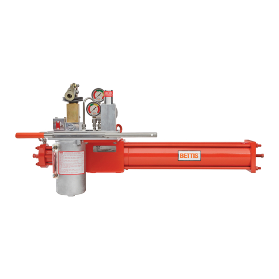
Section 2: Introduction Installation and Maintenance Manual E-90090005 Rev. A March 2014 Section 2: Introduction 2�1 General Service Information BETTIS™ PressureGuard™ is a self-contained hydraulic Emergency Shutdown (ESD) system. It is designed to provide reliable valve shutdown on production wellheads in remote locations where automatic local valve ESD is required, but a power source is not available and/or local supervision is minimal. -
Page 6: Definition Of Terms
Section 2: Introduction Installation and Maintenance Manual March 2014 E-90090005 Rev. A 2�2 Definition of Terms The abbreviations included in this IOM manual are listed in the table below: Table 1� Definition of Terms Abbreviated Term Definition Installation, Operation, and Maintenance Self-Contained Hydraulic Emergency Shutdown Gate Valve Operator Series... -
Page 7: Section 3: Storage Instructions
Installation and Maintenance Manual Section 3: Storage Instructions E-90090005 Rev. A March 2014 Section 3: Storage Instructions Proper storage is required when the operator will not be used immediately. Remove all dirt, dust, grease, and contaminants from any exposed, unpainted surface (for example, Drive Rod OD, Yoke ID) by using a soft cloth dampened with an appropriate oil based solvent. -
Page 8: Section 4: Operation
Section 4: Operation Installation and Maintenance Manual March 2014 E-90090005 Rev. A Section 4: Operation Before operating BETTIS™ PressureGuard™ system, it is critical to know its components and understand what they do. Refer to Figure 1. (SCH Module Portion of BETTIS PressureGuard™) , Figure 3. -
Page 9: Manual Mode
Installation and Maintenance Manual Section 4: Operation E-90090005 Rev. A March 2014 4�1 Manual Mode Lift/pull the toggle on the Reset Valve (23) and latch it in the upward position (pane #1 of Figure 2. (Three Modes of Reset Valve)) . Stroke the Handpump (3) to pressurize the SCH module and begin applying pressure to the operator’s Piston (refer to Appendix C (List of Drawings) for diagrams of typical rotary and linear operators) to move the valve to its... -
Page 10: Automatic Mode
Section 4: Operation Installation and Maintenance Manual March 2014 E-90090005 Rev. A 4�2 Automatic Mode The primary mode for BETTIS™ PressureGuard™ is its Automatic Mode. This is the mode in which the system is to be set in the field when technicians are not actively inspecting or maintaining wellhead components or resetting the system. -
Page 11: Section 5: Installation
Installation and Maintenance Manual Section 5: Installation E-90090005 Rev. A March 2014 Section 5: Installation Figure 3 BETTIS™ PressureGuard™ Schematic� Installation... - Page 12 Section 5: Installation Installation and Maintenance Manual March 2014 E-90090005 Rev. A Table 2� BETTIS™ PressureGuard™ Components and Descriptions Item Component Description Operator Rotary or linear (shown) hydraulic operator. Ball, plug, and others, quarter turn or non-6A linear valve Line Valve (shown).
- Page 13 Installation and Maintenance Manual Section 5: Installation E-90090005 Rev. A March 2014 5�1 SCH Installation Please refer to Figure 3. (BETTIS PressureGuard™ Schematic) for an example of ESD system. While not necessarily a typical configuration, Figure 3. (BETTIS PressureGuard™ Schematic) illustrates the connections, operating method, and a variety of sensing and control options available from BETTIS™...
- Page 14 Section 5: Installation Installation and Maintenance Manual March 2014 E-90090005 Rev. A Common components of a low and high pressure systems include: • Reset Valve requiring 40 to 60 [psi] on the signal port to sustain auto mode. The reset valve may also be referred to as ‘pilot to close valve’, ‘toggle valve’, or ‘manual pilot valve’.
- Page 15 Installation and Maintenance Manual Section 5: Installation E-90090005 Rev. A March 2014 NOTE: Check all hydraulic connections for leak. 5�2 Operator Installation BETTIS™ PressureGuard™ system is usually delivered from the factory with the SCH module installed on the operator. In this case, install the system per the instructions provided in the Installation, Operation, and Maintenance manual applicable to the type of operator in the system.
-
Page 16: Section 6: Maintenance
Section 6: Maintenance Installation and Maintenance Manual March 2014 E-90090005 Rev. A Section 6: Maintenance NOTE: It is recommended to read this manual entirely prior to performing any maintenance work on BETTIS™ PressureGuard™. Contact BETTIS™ for assistance should the technician have any questions or feel that a certain procedure cannot be performed safely. -
Page 17: Troubleshooting
Isolation Test Valve (28) (Pressure Pilot (14) and/or Solenoid (20)). Top up the hydraulic fluid with compatible fluid. Refer to BETTIS™ Pressurematic™ manual (document number ‘I-0220’, available from the factory or online at ‘www.emerson.com’). 2� Operator Maintenance Routine maintenance is required for the operator to function as designed. Refer to the IOM manual for the specific type of operator in the system per Table 3. - Page 18 Section 6: Maintenance Installation and Maintenance Manual March 2014 E-90090005 Rev. A Remove the filter plug, spring, and filter in Handpump sub plate to observe the backside of HP discharge. Check for leakage across and around it with high pressure being applied. Remove the fitting and tubing or plug from module second vent port to observe any oil leakage due to manifold porosity between the LP channel and the Vent channel.
-
Page 19: Section 7: Document Revision
Installation and Maintenance Manual Section 7: Document Revision E-90090005 Rev. A March 2014 Section 7: Document Revision Table 4� Revision Overview DATE BY * DATE Released COMPILED J. Quilon March 2014 Reviewed CHECKED March 2014 Approved APPROVED E. Carrillo April 2014 Document Revision... -
Page 20: Appendix A: List Of Tables
Appendix Installation and Maintenance Manual March 2014 E-90090005 Rev. A Appendix A: List of Tables Table 1. Definition of Terms ....................3 Table 2. BETTIS™ PressureGuard™ Components and Descriptions ........9 Table 3. Operators and IOM Manuals ................12 Table 4. Revision Overview .................... -
Page 21: Appendix B: List Of Figures
Installation and Maintenance Manual Appendix E-90090005 Rev. A March 2014 Appendix B: List of Figures Figure 1. SCH Module Portion of BETTIS™ PressureGuard™ ..........5 Figure 2. Three Modes of Reset Valve ................. 6 Figure 3. BETTIS™ PressureGuard™ Schematic ..............8 Appendix... -
Page 22: Appendix C: List Of Drawings
Appendix Installation and Maintenance Manual March 2014 E-90090005 Rev. A Appendix C: List of Drawings C�1 SCH Module and Components Appendix... - Page 23 Installation and Maintenance Manual Appendix E-90090005 Rev. A March 2014 Appendix...
- Page 24 Appendix Installation and Maintenance Manual March 2014 E-90090005 Rev. A Appendix...
- Page 25 Installation and Maintenance Manual Appendix E-90090005 Rev. A March 2014 Appendix...
- Page 26 Appendix Installation and Maintenance Manual March 2014 E-90090005 Rev. A Appendix...
- Page 27 Installation and Maintenance Manual Appendix E-90090005 Rev. A March 2014 C�2 GVO-FS Operator Cutaway and Components Appendix...
- Page 28 Appendix Installation and Maintenance Manual March 2014 E-90090005 Rev. A C�3 Quarter-Turn Operator Cutaway and Components Appendix...
- Page 30 Tianjin 301700 Holland Fasor 6 P. R. China Székesfehérvár 8000 The Emerson logo is a trademark and service mark of Emerson Electric Co. T +86 22 8212 3300 Hungary Bettis is a mark of one of the Emerson family of companies.