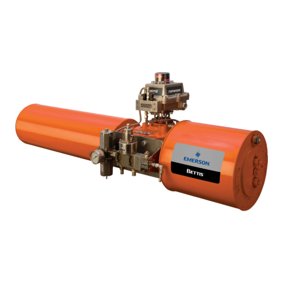
Summary of Contents for Emerson Bettis G Series
- Page 1 Installation, Operation and Maintenance Manual VA-DC-000-1931 Rev. 0 January 2021 Bettis G-Series Acculine Drive Shaft Replacement...
- Page 2 Notes Installation, Operation and Maintenance Manual January 2021 VA-DC-000-1931 Rev. 0 This page intentionally left blank.
-
Page 3: Table Of Contents
Installation, Operation and Maintenance Manual Table of Contents VA-DC-000-1931 Rev. 0 January 2021 Table of Contents Section 1: Introduction General Service Information ................1 Definitions ....................2 General Safety Information ................2 Service Support Items ................... 3 Lubrication and Fluid Requirements .............. 3 Section 2: Removal and Installation Acculine Drive Shaft Removal ................ - Page 4 Notes Installation, Operation and Maintenance Manual January 2021 VA-DC-000-1931 Rev. 0 This page intentionally left blank.
-
Page 5: Section 1: Introduction
Section 1: Introduction Installation, Operation and Maintenance Manual VA-DC-000-1931 Rev. 0 January 2021 Section 1: Introduction General Service Information 1.1.1 This service procedure is offered as a guide to enable Bettis™ Acculine drive shaft replacement to be performed on Bettis™ G01 - G13 G-Series Actuators. 1.1.2 This procedure is applicable with the understanding that all electrical power and pneumatic pressure has been removed from the actuator. -
Page 6: Definitions
Section 1: Introduction Installation, Operation and Maintenance Manual January 2021 VA-DC-000-1931 Rev. 0 Definitions WARNING If not observed, user incurs a high risk of severe damage to actuator and/or fatal injury to personnel. CAUTION If not observed, user may incur damage to actuator and/or injury to personnel. NOTE: Advisory and information comments provided to assist maintenance personnel to carry out maintenance procedures. -
Page 7: Service Support Items
Section 1: Introduction Installation, Operation and Maintenance Manual VA-DC-000-1931 Rev. 0 January 2021 Service Support Items 1.4.1 Bettis module service kits. Commercial leak testing solution. 1.4.2 1.4.3 Non-hardening thread sealant. Lubrication and Fluid Requirements NOTE: Lubricants and hydraulic fluids other than those listed in steps 1.5.1 and 1.5.2 should not be used without prior written approval of Bettis Product Engineering. -
Page 8: Section 2: Removal And Installation
Section 2: Removal and Installation Installation, Operation and Maintenance Manual January 2021 VA-DC-000-1931 Rev. 0 Section 2: Removal and Installation Acculine Drive Shaft Removal WARNING It is possible, that the actuator may contain a dangerous gas and/or liquids. Ensure that all proper measures have been taken to prevent exposure or release of these types of contaminants before commencing any work. - Page 9 Installation, Operation and Maintenance Manual Section 2: Removal and Installation VA-DC-000-1931 Rev. 0 January 2021 2.1.2 Remove the yoke cover (1 - 150) from the actuator. Figure 2 2.1.3 Remove the position indicator assembly (1 - 140) from the actuator. Figure 3 Removal and Installation...
-
Page 10: New Acculine Drive Shaft Installation
Section 2: Removal and Installation Installation, Operation and Maintenance Manual January 2021 VA-DC-000-1931 Rev. 0 2.1.4 Use proper tools to remove the spring pin (1 - 100) from the actuator. Figure 4 New Acculine Drive Shaft Installation NOTE: Properly clean the surfaces before installation to ensure better actuator performance. 2.2.1 Insert the new spring pin (1 - 100) into the yoke, spring pin is provided in the service kit. - Page 11 Installation, Operation and Maintenance Manual Section 2: Removal and Installation VA-DC-000-1931 Rev. 0 January 2021 2.2.2 Pull the new position indicator assembly (1 - 140) out from the new yoke cover (1 - 150). Figure 6 Place the new position indicator assembly (1 - 140) onto the yoke (1 - 70), 2.2.3 make sure the spring pin (1 - 100) is in the slot of the position indicator assembly (1 - 140) plate.
- Page 12 Section 2: Removal and Installation Installation, Operation and Maintenance Manual January 2021 VA-DC-000-1931 Rev. 0 CAUTION Pay attention to the O-ring seals in steps 2.2.4 and 2.2.5. 2.2.4 Install new yoke cover assembly (1 - 150) to the housing cover (1 - 20). Figure 8 2.2.5 Install and tighten the new Hex head screws (1 - 160) and washers (1 - 170).
-
Page 13: Section 3: Actuator Support Information
Installation, Operation and Maintenance Manual Section 3: Actuator Support Information VA-DC-000-1931 Rev. 0 January 2021 Section 3: Actuator Support Information G01 Tool Style and Wrench Size Table 1. G01 Tool Style and Wrench Size Location or Recommended Item No. Wrench Size Item Qty. -
Page 14: G2 Tool Style And Wrench Size
Section 3: Actuator Support Information Installation, Operation and Maintenance Manual January 2021 VA-DC-000-1931 Rev. 0 G2 Tool Style and Wrench Size Table 2. G2 Tool Style and Wrench Size Location or Recommended Item No. Wrench Size Item Qty. Description Tool Style 1 - 110 9/16”... -
Page 15: G4 Tool Style And Wrench Size
Installation, Operation and Maintenance Manual Section 3: Actuator Support Information VA-DC-000-1931 Rev. 0 January 2021 G4 Tool Style and Wrench Size Table 4. G4 Tool Style and Wrench Size Location or Recommended Item No. Wrench Size Item Qty. Description Tool Style 1 - 110 9/16”... -
Page 16: G7 Tool Style And Wrench Size
Section 3: Actuator Support Information Installation, Operation and Maintenance Manual January 2021 VA-DC-000-1931 Rev. 0 G7 Tool Style and Wrench Size Table 6. G7 Tool Style and Wrench Size Location or Recommended Item No. Wrench Size Item Qty. Description Tool Style 1 - 110 3/4”... -
Page 17: G10 Tool Style And Wrench Size
Installation, Operation and Maintenance Manual Section 3: Actuator Support Information VA-DC-000-1931 Rev. 0 January 2021 G10 Tool Style and Wrench Size Table 8. G10 Tool Style and Wrench Size Location or Recommended Item No. Wrench Size Item Qty. Description Tool Style 1 - 110 3/4”... - Page 18 Tianjin 301700 Holland Fasor 6 P. R. China Székesfehérvár 8000 The Emerson logo is a trademark and service mark of Emerson Electric Co. T +86 22 8212 3300 Hungary Bettis is a mark of one of the Emerson family of companies.


