
Related Manuals for Emerson Bettis 500


Summary of Contents for Emerson Bettis 500
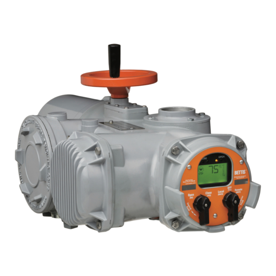
- Page 1 Installation and Operation Manual E2K-405-0218 Rev. 2 February 2018 TEC2 Electric Actuator with Model 500...
-
Page 3: Table Of Contents
Installation and Operation Manual Table of Contents E2K-405-0218 Rev. 2 February 2018 Table of Contents Section 1: Important Notes User Safety ....................1 Purpose ......................1 Storage Procedures ..................2 Section 2: Quick Start Set Position Limits ..................3 Network Setup ....................8 Check Settings .................... - Page 4 Table of Contents Installation and Operation Manual February 2018 E2K-405-0218 Rev. 2 Section 5: Customizing Actuator Settings Entering Setup Mode .................. 40 Setting Limits ....................42 Changing Display ..................42 Displaying Unit Parameters ................. 43 Change Settings ..................45 5.5.1 Passcode Entry .................
- Page 5 Installation and Operation Manual Table of Contents E2K-405-0218 Rev. 2 February 2018 Section 8: Regulatory Information Appendix A: Exploded View (Model-500 Torque Unit Only) ..........82 M-500 with Thrust Base Installation Drawing ..........83 Module Identification and Location ............. 85 Infrared Controller (IRC) –...
- Page 6 Table of Contents Installation and Operation Manual February 2018 E2K-405-0218 Rev. 2 List of Figures Figure 2-1 Declutch Lever and Handwheel ................. 5 Figure 2-2 Setting Limits – Electrical Operation ..............6 Figure 2-3 Setting Limits – Manual Operation ..............7 Figure 3-1 Preparing the Stem Nut ..................
- Page 7 Installation and Operation Manual Table of Contents E2K-405-0218 Rev. 2 February 2018 List of Figures (continuation) Figure 5-1 Setup ......................41 Figure 5-2 Change Display ....................43 Figure 5-3 Displaying Unit Parameters ................44 Figure 5-4 Change Settings ....................46 Figure 5-5 Passcode Entry ....................
- Page 8 Table of Contents Installation and Operation Manual February 2018 E2K-405-0218 Rev. 2 List of Tables Table 3-1 Connecting Actuator A to Actuator B ..............22 Table 3-2 ARM Wiring Connections .................. 23 Table 3-3 RDM Connections with Internal Power Source (24VDC) ........27 Table 3-4 RDM Connections with External Power Source (External AC) ......
-
Page 9: Section 1: Important Notes
Installation and Operation Manual Section 1: Important Notes E2K-405-0218 Rev. 2 February 2018 Section 1: Important Notes User Safety Safety notices in this manual detail precautions the user must take to reduce the risk of personal injury and damage to the equipment. The user must read these instructions in their entirety. -
Page 10: Storage Procedures
This will ensure optimum performance from your TEC2 actuator. Failure to comply with recommended procedures could lead to actuator malfunction and will void the warranty. For storage procedures exceeding one year, contact your local Emerson Representative for recommendations. The TEC2 actuator is a double-sealed and inherently weatherproof unit when shipped from the factory, providing that all compartment covers and cable entry plugs remain intact. -
Page 11: Section 2: Quick Start
Installation and Operation Manual Section 2: Quick Start E2K-405-0218 Rev. 2 February 2018 Section 2: Quick Start The Quick Start Section provides step-by-step instructions for initializing the TEC2 actuator. When these instructions are complete, the position limits will be set and the actuator will be ready for normal operation. - Page 12 Section 2: Quick Start Installation and Operation Manual February 2018 E2K-405-0218 Rev. 2 CAUTION: It is recommended the valve be positioned using the handwheel while setting the limits to prevent valve damage. Valve Operation For Electrical Operation use the control knob to move the valve in the close direction.
-
Page 13: Figure 2-1 Declutch Lever And Handwheel
Installation and Operation Manual Section 2: Quick Start E2K-405-0218 Rev. 2 February 2018 The position limits are now set. The actuator will operate in the normal LOCAL and REMOTE modes. NOTE: The user is not required to exit setup after setting limits for the first time. At the completion of setting the limits, the actuator should be in the “STOP”... -
Page 14: Figure 2-2 Setting Limits - Electrical Operation
Section 2: Quick Start Installation and Operation Manual February 2018 E2K-405-0218 Rev. 2 Figure 2-2 Setting Limits Figure 2-2 Setting Limits - Electrical Operation Electrical Operation Are Limits Set? Set Local and Close Valve LOCAL (BACK) Open Valve Then Select Close Valve Then Select STOP... -
Page 15: Figure 2-3 Setting Limits Manual Operation
Installation and Operation Manual Section 2: Quick Start E2K-405-0218 Rev. 2 February 2018 Figure 2-3 Setting Limits - Manual Operation Figure 2-3 Setting Limits Manual Operation Are Limits Set? Set Local and Close Valve LOCAL (BACK) Open Valve Close Valve Then Then Select Select... -
Page 16: Network Setup
Section 2: Quick Start Installation and Operation Manual February 2018 E2K-405-0218 Rev. 2 Network Setup This is only applicable if the Controlinc Auxiliary Control Module (ACM) and the Communication Adapter Module (CAM) are installed and enabled. These instructions assume all parameters have been set with the exception of the network node address. Remain in the “SETUP”... -
Page 17: Section 3: Installation
Installation and Operation Manual Section 3: Installation E2K-405-0218 Rev. 2 February 2018 Section 3: Installation WARNING: Failure to follow instructions for proper electrical wiring, storage, setup, and maintenance may cause serious injury, damage equipment, or void warranty. WARNING: Use caution when working on, with, or around valves and actuators. High pressures, forces, voltages, and flammable media can be present. -
Page 18: Mechanical Installation Onto The Valve
Tighten to a preload. See Appendix for common bolt tightening torques. NOTE: Mounting screws are provided only if Emerson supplied the adapter. Verify screws are through the adapter; engage a minimum of one screw diameter deep into the actuator base. -
Page 19: Electrical Connections
Installation and Operation Manual Section 3: Installation E2K-405-0218 Rev. 2 February 2018 Electrical Connections 3.3.1 Remove Separate Terminal Chamber (STC) Cover WARNING: BEWARE OF MULTIPLE POWER SOURCES Verify power is disconnected before removing STC Cover. Multiple power sources may exist under the cover. NOTE: Valve actuator requires a circuit breaker within the line of sight, sized for the motor currently specified on the nameplate. -
Page 20: Sealing Cable/Conduit Entries
Section 3: Installation Installation and Operation Manual February 2018 E2K-405-0218 Rev. 2 3.3.2 Sealing Cable/Conduit Entries Seal the cable and conduit entries in accordance with the National Electric Code or your country standard and applicable local codes. All conduit entries should be sealed against the site environment. -
Page 21: Cable Connections
Installation and Operation Manual Section 3: Installation E2K-405-0218 Rev. 2 February 2018 Figure 3-3 Control Terminal Connections Figure 3-4 Power Terminal Connections 3.3.4 Cable Connections Connect the main power supply cables, including the earth/ground wire using #1 Phillips or 3/16 inch (5mm) slotted tip screwdriver. Attach earth/ground wire to internal ground lug using 1/4 inch #11 slotted screwdriver. -
Page 22: Display Backup Module (Dbm) - Optional
Section 3: Installation Installation and Operation Manual February 2018 E2K-405-0218 Rev. 2 Figure 3-5 Earth/Ground Connection Display Backup Module (DBM) – Optional The DBM is a battery pack containing two 9V Lithium battery clips. This battery pack provides power to the electronics, but does not power the motor control circuits or the 24 Vdc power supply. -
Page 23: Discrete Controlled Inputs
Installation and Operation Manual Section 3: Installation E2K-405-0218 Rev. 2 February 2018 NOTE: The battery should not be enabled until the unit is field commissioned and ready for power to be applied. The battery can only be replaced with an Ultralife U9VL 9V battery. To prevent losing the clock settings, install one new battery before removing one old one. -
Page 24: Figure 3-7 Inhibit And Esd Wiring
Section 3: Installation Installation and Operation Manual February 2018 E2K-405-0218 Rev. 2 Figure 3-7 Inhibit and ESD Wiring A. External Power Supply External Open Inhibit Power Supply Close Inhibit 18-150 VDC 0V common 20-250 VAC B. Internal Power Supply Open Inhibit Close Inhibit Internal Power... -
Page 25: Auxiliary Control Module (Acm) - Optional
Installation and Operation Manual Section 3: Installation E2K-405-0218 Rev. 2 February 2018 Auxiliary Control Module (ACM) – Optional The ACM is an optional module used to expand the functionality of the TEC2 actuator. There are several versions of the ACM available: Futronic, Controlinc, and Auxiliary Relay Module (ARM). -
Page 26: Figure 3-10 Acm Installation Connections - Acm (Network Control Module)
Section 3: Installation Installation and Operation Manual February 2018 E2K-405-0218 Rev. 2 Figure 3-10 ACM Installation Connections - ACM (Network Control Module) Alternate Default Signal Function Function Open Digital Input #1 Close Digital Input #2 Stop Digital Input #3 AIN1+ Common (0V) for Control Inputs (1-3) AIN1- AIN2+... -
Page 27: Analog Controlled - Power Supply Connections
Installation and Operation Manual Section 3: Installation E2K-405-0218 Rev. 2 February 2018 3.6.2 Analog Controlled – Power Supply Connections The power sources for analog controlled inputs/outputs are either internal or external. Connect the power supplies as shown in Figure 3-12 through Figure 3-17. -
Page 28: Figure 3-14 Acm - Analog Input With External Power Supply
Section 3: Installation Installation and Operation Manual February 2018 E2K-405-0218 Rev. 2 Figure 3-14 ACM – Analog Input with External Power Supply 24 VDC AIN#1 AIN#2 Earth Figure 3-15 ACM– Analog Input with Internal Power Supply 24 VDC AIN#1 AIN#2 Earth Installation... -
Page 29: Figure 3-16 Futronic - 3 Wire Analog Control With External Power Supply
Installation and Operation Manual Section 3: Installation E2K-405-0218 Rev. 2 February 2018 Figure 3-16 Futronic – 3 Wire Analog Control with External Power Supply External Power Supply External Power Open Open Supply Close Close 18-150VDC 3-Wire 20-250VAC Toggle Common 0v 4-20mA Position Set Point External 24VDC Input... -
Page 30: Network Controlled
Section 3: Installation Installation and Operation Manual February 2018 E2K-405-0218 Rev. 2 3.6.3 Network Controlled For the actuator to be network controlled, a Controlinc ACM and a Communication Adapter Module (CAM) must be installed. Each CAM is required for a specific protocol and network topology, and enables the network capability. -
Page 31: Auxiliary Relay Module (Arm) Wiring
Installation and Operation Manual Section 3: Installation E2K-405-0218 Rev. 2 February 2018 Auxiliary Relay Module (ARM) Wiring The ARM can be used with the Futronic ACM or standalone. Only factory-trained technicians may install the ARM. Connect the ARM within the controller in accordance with Table 3-2. See Section 3.3, Electrical Connections for general electrical connection requirements. -
Page 32: Figure 3-19 Arm Wiring Connections
Section 3: Installation Installation and Operation Manual February 2018 E2K-405-0218 Rev. 2 Figure 3-19 ARM Wiring Connections ARM Wiring Terminals 39 to 44 Installation... -
Page 33: Remote Display Module (Rdm) Connection To The Actuator - Optional
Installation and Operation Manual Section 3: Installation E2K-405-0218 Rev. 2 February 2018 Remote Display Module (RDM) Connection to the Actuator – Optional Connect the RDM to the actuator as shown in Figure 3-20 and in accordance with Section 3.8.1, 24 Vdc Power Source, or Section 3.8.2, 115/230 Vac Power Source, depending on the power source. -
Page 34: 24 Vdc Power Source
Section 3: Installation Installation and Operation Manual February 2018 E2K-405-0218 Rev. 2 3.8.1 24 Vdc Power Source If the RDM is to receive power from the actuator, connect cable type Belden 8723 or equivalent as detailed in Table 3-3. The cable distance is limited to 1,200 feet (366 meters). -
Page 35: 115/230 Vac Power Source
Installation and Operation Manual Section 3: Installation E2K-405-0218 Rev. 2 February 2018 Table 3-3. RDM Connections with Internal Power Source (24VDC) RDM Interface Module Function TEC2 STC Terminals Connector P2 P2-10 (24V +) 24 Vdc(+) P2-9 (24V -) 0V Common P2-3 (CHA -) RS-485 (-) P2-5 (CHA +) -
Page 36: Figure 3-22 Tec2 Wiring Diagram
Section 3: Installation Installation and Operation Manual February 2018 E2K-405-0218 Rev. 2 Figure 3-22 TEC2 Wiring Diagram 3 - Phase Motor Power Thermal Motor Protector Control Supply Module Open Close 24 VDC Power Stop Supply Common 0V Open Inhibit Central Control Module Close Inihbit Note: Maximum Power Rating: 15.12 Watts Maximum Source Current: 0.63 Amps... -
Page 37: Section 4: Operation
Installation and Operation Manual Section 4: Operation E2K-405-0218 Rev. 2 February 2018 Section 4: Operation Figure 4-1 TEC2 Controller Local Display Module Display Module with Bluetooth - Model 87340. ® See Appendix for Specifications. The Local Display module consists of the following as shown in Figure 4-2: •... -
Page 38: Graphics Display And Message Center
Section 4: Operation Installation and Operation Manual February 2018 E2K-405-0218 Rev. 2 4.1.1 Graphics Display and Message Center The graphics display shows the mode of operation, valve status, position, torque, and alarm symbols. The message center displays actuator setup selections, data entry feedback, and alarm messages. -
Page 39: Normal Display Function
Installation and Operation Manual Section 4: Operation E2K-405-0218 Rev. 2 February 2018 4.1.4 Normal Display Function Figure 4-3 details the display during normal function. The bar graphs, position digits, icons, and LEDs indicate normal activity, i.e., the valve opening, closing, or stopping in mid-travel. -
Page 40: Remote Display Module (Rdm) Display Module With Bluetooth
Section 4: Operation Installation and Operation Manual February 2018 E2K-405-0218 Rev. 2 Remote Display Module (RDM) Display Module with Bluetooth - Model 87340 ® See Appendix for Specifications. The RDM performs the same functions as the LDM. NOTE: If the RDM does not receive communication messages from the Central Control Module (CCM) within 5 seconds after power is applied, the RDM will display the flashing message “CCM LINK FAILED”... -
Page 41: Initializing The Actuator
Installation and Operation Manual Section 4: Operation E2K-405-0218 Rev. 2 February 2018 Initializing the Actuator NOTE: The TEC2 has automatic phase correction. 4.3.1 Setting Position Limits Limits must be set before operating. The actuator will not operate until limits are set. NOTE: A passcode is not needed for the initial position limit settings. -
Page 42: Table 4-4 Default Configuration Settings
Section 4: Operation Installation and Operation Manual February 2018 E2K-405-0218 Rev. 2 Table 4-4. Default Configuration Settings Basic Actuator Functions Discrete Outputs Valve Discrete Inhibit and ESD (Relays (ARM Relays Control Inputs 1 thru 5) 9 thru 12) DI#1= Active on RO#9 = Lost Power Mode = 3 Wire RO#1= LSO... - Page 43 Installation and Operation Manual Section 4: Operation E2K-405-0218 Rev. 2 February 2018 Two-Speed Timer Default Configuration Close Open Anti-Water Hammer Mode = OFF Mode = OFF Mode = OFF Start Position = 30% Start Position = 70% Start Position = 10% Stop Position = 1% Stop Position = 99% Pulse ON time = 3.5 Sec...
-
Page 44: Figure 4-4 Display Settings
Section 4: Operation Installation and Operation Manual February 2018 E2K-405-0218 Rev. 2 Figure 4-4 Display Settings Figure 4-5 Display Settings Go to Figure 5-1 BACK NEXT BACK VALVE CONTROL Control Mode Drive Sleeve <pos or trq> Torque Close Torque SETUP? <control mode>... -
Page 45: Local Control Operation
Installation and Operation Manual Section 4: Operation E2K-405-0218 Rev. 2 February 2018 Local Control Operation To locally control the actuator via the LDM or the RDM: Exit “SETUP” mode if applicable. Place the selector knob in the LOCAL position. NOTE: The actuator is shipped configured for inching mode unless specified at the time order is placed;... -
Page 46: Remote/Auto Control Operation
Section 4: Operation Installation and Operation Manual February 2018 E2K-405-0218 Rev. 2 Remote/Auto Control Operation The actuator is shipped configured for “four-wire control” unless otherwise specified at order placement. There are additional remote control modes that can be selected via the “SETUP”... -
Page 47: February
Installation and Operation Manual Section 4: Operation E2K-405-0218 Rev. 2 February 2018 Two-Wire Control The two-wire control mode uses only one contact to control the valve. When the contact is closed, the valve opens, and when the contact is open, the valve closes. The contact open and close status can be reversed in the “SETUP”... -
Page 48: Section 5: Customizing Actuator Settings
Section 5: Customizing Actuator Settings Installation and Operation Manual February 2018 E2K-405-0218 Rev. 2 Section 5: Customizing Actuator Settings Entering Setup Mode The “SETUP” mode must be entered to modify any configuration settings. Place the selector knob in the STOP position. Setup may be performed at any one location;... -
Page 49: Figure 5-1 Setup
Installation and Operation Manual Section 5: Customizing Actuator Settings E2K-405-0218 Rev. 2 February 2018 Figure 5-1 Setup Figure 5-1 Setup Go to Are Limits Set? SETUP? Figure 5-7 Go to Display Unit Figure 5-3 Parameters? Go to Change Settings? Figure 5-4 Go to Display Figure 4-5... -
Page 50: Setting Limits
Section 5: Customizing Actuator Settings Installation and Operation Manual February 2018 E2K-405-0218 Rev. 2 Setting Limits After entering “SETUP” mode, the alarm message “SET LIMITS BEFORE OPERATING” will appear if limits have not been set. See Section 4.3.1, Setting Position Limits, to set the limits for the first time. -
Page 51: Displaying Unit Parameters
Installation and Operation Manual Section 5: Customizing Actuator Settings E2K-405-0218 Rev. 2 February 2018 Figure 5-2 Change Display Figure 5-2 Change Display BACK NEXT Go to Figure 5-15 BACK Change Language? Adjust No to Adjust CHANGE Language? <xxxxxxxx> Contrast? Yes to Accept DISPLAY? Next English, Spanish,Portuguese,... -
Page 52: Figure 5-3 Displaying Unit Parameters
Section 5: Customizing Actuator Settings Installation and Operation Manual February 2018 E2K-405-0218 Rev. 2 Figure 5-3 Displaying Unit Parameters Figure 5-3 Displaying Unit Parameters Go to Figure 5-2 BACK NEXT BACK Tag Name: Control Mode: Network Adapter: Network Node DISPLAY UNIT <16 character max>... -
Page 53: Change Settings
Installation and Operation Manual Section 5: Customizing Actuator Settings E2K-405-0218 Rev. 2 February 2018 Change Settings Enter “SETUP” mode and use the selector knob (NEXT) to scroll to “CHANGE SETTINGS?”. Answer “YES.” See Section 5.1, Entering Setup Mode. Enter passcode. NOTE: A passcode must be entered to change settings. -
Page 54: Figure 5-4 Change Settings
Section 5: Customizing Actuator Settings Installation and Operation Manual February 2018 E2K-405-0218 Rev. 2 Figure 5-4 Change Settings Figure 5-4 Change Settings Displayed only if ACM Installed ANALOG SAVE CHANGE and ANALOG control is enabled. SETUP? SETTINGS? See Figure 5-13 BACK CHANGE Is Controlinc ACM... -
Page 55: Passcode Entry
Installation and Operation Manual Section 5: Customizing Actuator Settings E2K-405-0218 Rev. 2 February 2018 5.5.1 Passcode Entry The actuator is shipped with “000” as a passcode. To change the passcode see Section 5.5.11, Passcode Setup. To enter the passcode: At the “CHANGE SETTINGS?” prompt answer “YES.” “ACCEPT PASSCODE CHARACTER 1? X”... -
Page 56: Valve Control Setup
Section 5: Customizing Actuator Settings Installation and Operation Manual February 2018 E2K-405-0218 Rev. 2 Figure 5-5 Passcode Entry Figure 5-5 Passcode Entry Go to Figure 5-3 BACK NEXT BACK CHANGE Is Passcode Is Passcode Accept Accept Accept SETTINGS? Passcode Passcode Passcode ‘000’? Correct? -
Page 57: Figure 5-6 Valve Control Setup
Installation and Operation Manual Section 5: Customizing Actuator Settings E2K-405-0218 Rev. 2 February 2018 Figure 5-6 Valve Control Setup Associated choices are listed below each setting. Figure 5-6 Valve Control Setup SAVE CHANGE BACK NEXT SETTINGS? BACK VALVE CONTROL Control Mode Position Bandwidth Speed Bandwidth Modulation Delay... -
Page 58: Set Valve Travel Limits
Section 5: Customizing Actuator Settings Installation and Operation Manual February 2018 E2K-405-0218 Rev. 2 5.5.3 Set Valve Travel Limits If the close limit is acceptable, answer “YES.” If not rotate the selector knob to LOCAL. Close valve to desired limit, rotate selector knob to STOP, and answer YES. -
Page 59: Figure 5-8 Set Valve Travel Limits Normal Operation Mode - Set Limits With Handwheel Operation
Installation and Operation Manual Section 5: Customizing Actuator Settings E2K-405-0218 Rev. 2 February 2018 Figure 5-8 Set Valve Travel Limits Normal Operation Mode - Set Limits with Handwheel Operation Figure 5-7 Normal Operation Mode - Set Limits With Electrical Operation Go to Figure 5-6 BACK... -
Page 60: Discrete Input Setup
Section 5: Customizing Actuator Settings Installation and Operation Manual February 2018 E2K-405-0218 Rev. 2 5.5.4 Discrete Input Setup At the “DISCRETE INPUT SETUP” prompt answer “YES.” Use the selector knob (NEXT/BACK) to review the setting for each discrete input. For Input DI #1, use the control knob (NO) to select either “ACTIVE ON CLOSED CONTACT”... -
Page 61: Discrete Output Setup
Installation and Operation Manual Section 5: Customizing Actuator Settings E2K-405-0218 Rev. 2 February 2018 5.5.5 Discrete Output Setup Relay outputs are used primarily for hard wired status feedback. Each relay may be configured (assigned) to various status, alarm, or control functions. Relay outputs can be configured to be active on the listed alarms/conditions. -
Page 62: Table 5-2 Relay Output Function List
Section 5: Customizing Actuator Settings Installation and Operation Manual February 2018 E2K-405-0218 Rev. 2 NOTE: Host Control means the control of this relay has been given to the network if a Controlinc card has been installed. The relay will not function if the Controlinc card is not installed. -
Page 63: Figure 5-10 Discrete Output Setup
Installation and Operation Manual Section 5: Customizing Actuator Settings E2K-405-0218 Rev. 2 February 2018 Figure 5-10 Discrete Output Setup Figure 5-10 Discrete Output Setup BACK NEXT DISCRETE Relay #1 Relay #1 Relay #1 Relay #2 Relay #2 Relay #1 <N.O. / N.C.> <cont / ash>... -
Page 64: Inhibit And Esd Setup
Section 5: Customizing Actuator Settings Installation and Operation Manual February 2018 E2K-405-0218 Rev. 2 Relays #9 through #12 are the auxiliary relays when the Auxiliary Relay Module (ARM) is installed. To configure these relay outputs, follow Step No.1 through No. 3 listed above. See Table 5-3. NOTE: The ARM cannot be added when the Controlinc ACM is installed. -
Page 65: Figure 5-11 Inhibit And Esd Setup
Installation and Operation Manual Section 5: Customizing Actuator Settings E2K-405-0218 Rev. 2 February 2018 Figure 5-11 Inhibit and ESD Setup Figure 5-11 Inhibit & ESD Setup INHIBIT & ESD Open Inhibit ESD Override On SETUP? <Yes=On; Thermal No=Off> <Yes=Off; No=On> ESD Override Close Inhibit On Local:... -
Page 66: Two-Speed Timer Setup
Section 5: Customizing Actuator Settings Installation and Operation Manual February 2018 E2K-405-0218 Rev. 2 5.5.7 Two-Speed Timer Setup The two-speed timers can be configured for the actuator to be controlled with different opening and closing times. All configured timers are active in the LOCAL and REMOTE modes. -
Page 67: Analog Setup (Acm Required)
Installation and Operation Manual Section 5: Customizing Actuator Settings E2K-405-0218 Rev. 2 February 2018 5.5.8 Analog Setup (ACM Required) NOTE: Only displayed/applicable if the ACM is installed and analog control is enabled in the valve control setup. See Section 5.5.2, Valve Control Setup. All analog I/O are loop powered. -
Page 68: Figure 5-13 Analog Setup
Section 5: Customizing Actuator Settings Installation and Operation Manual February 2018 E2K-405-0218 Rev. 2 Figure 5-13 Analog Setup NOTE: The actuator senses that the Futronic ACM is installed and adjusts the display sequence to display only one input. Figure 5-13 Analog Setup Go to Figure 5-13 BACK Position... -
Page 69: Figure 5-13-1 Analog Input 1 Calibration Setup
Installation and Operation Manual Section 5: Customizing Actuator Settings E2K-405-0218 Rev. 2 February 2018 Figure 5-13-1 Analog Input 1 Calibration Setup Figure 5-13-1 Analog Input 1 Calibration Setup Return to Analog Setup? In Figure 5-13 BACK Calibrate AIN #1 4-20MA? Calibrate 4MA Reference Accept... -
Page 70: Figure 5-13-2 Analog Input 2 Calibration Setup
Section 5: Customizing Actuator Settings Installation and Operation Manual February 2018 E2K-405-0218 Rev. 2 Figure 5-13-2 Analog Input 2 Calibration Setup Figure 5-13-2 Analog Input 2 Calibration Setup Return to Analog Setup? In Figure 5-13 BACK Calibrate AIN #2 4-20MA? Calibrate 4MA Reference Accept... -
Page 71: Figure 5-13-3 Analog Output 1 Calibration Setup
Installation and Operation Manual Section 5: Customizing Actuator Settings E2K-405-0218 Rev. 2 February 2018 Figure 5-13-3 Analog Output 1 Figure 5-13-3 Analog Output 1 Calibration Setup Calibration Setup Go to Calibrate Figure 5-13-2 AO#1 4-20MA? Calibrate Is External Meter Accept 4MA 4MA? Connected? Setting? -
Page 72: Figure 5-13-4 Analog Output 2 Calibration Setup
Section 5: Customizing Actuator Settings Installation and Operation Manual February 2018 E2K-405-0218 Rev. 2 Figure 5-13-5 Analog Output 2 Figure 5-13-4 Analog Output 2 Calibration Setup Calibration Setup Return to Analog Setup? Calibrate In Figure 5-13 AO#2 4-20MA? Calibrate Is External Meter Accept 4MA 4MA? Connected? -
Page 73: Network Setup (Cam And Controlinc Acm Required)
Installation and Operation Manual Section 5: Customizing Actuator Settings E2K-405-0218 Rev. 2 February 2018 5.5.9 Network Setup (CAM and Controlinc ACM Required) NOTE: Only displayed/applicable if the Communication Adapter Module (CAM) and the ControIinc ACM are installed, and the network control is enabled. See Section 5.5.2, Valve Control Setup. -
Page 74: Figure 5-14 Network Setup
Section 5: Customizing Actuator Settings Installation and Operation Manual February 2018 E2K-405-0218 Rev. 2 Figure 5-14 Network Setup NOTE: The actuator senses that the Controlinc ACM is installed and adjusts the display sequence to display only one output. Figure 5-14 Network Setup Go to Figure 5-4... -
Page 75: Figure 5-14-1 Network Setup Display Menu
Installation and Operation Manual Section 5: Customizing Actuator Settings E2K-405-0218 Rev. 2 February 2018 Figure 5-14 Setup Figure 5-14-1 Network Setup Display Menu Display Menu Go to Figure 5-13 Chan A Word Length? <wlength> BACK NETWORK Network Node SETUP? Address <xxx> <001-245>... -
Page 76: 5.5.10 Tag Name Setup
Section 5: Customizing Actuator Settings Installation and Operation Manual February 2018 E2K-405-0218 Rev. 2 5.5.10 Tag Name Setup At the “TAG NAME SETUP?” prompt, answer, “YES.” Use the control knob (NO) to increment the data entry selection for each character. NOTE: The tag name consists of a maximum of sixteen characters. -
Page 77: 5.5.11 Passcode Setup
Installation and Operation Manual Section 5: Customizing Actuator Settings E2K-405-0218 Rev. 2 February 2018 5.5.11 Passcode Setup The passcode may be changed via the passcode setup sequence. At the “PASSCODE SETUP?” prompt, answer “YES.” Use the control knob (NO) to increment the data entry selections of 0-9 and A-Z for each character. -
Page 78: Figure 5-17 Battery Enable Menu
Menu Setup Section 5: Customizing Actuator Settings Installation and Operation Manual February 2018 E2K-405-0218 Rev. 2 Go to TAG NAME SETUP MENU Figure 5-13 Figure 5-15 BACK NEXT BACK Figure 5-17 Battery Enable Menu Continue this process TAG NAME for 16 characters ACCEPT? ACCEPT? ACCEPT? -
Page 79: 5.5.12 Reload Factory Settings
Installation and Operation Manual Section 5: Customizing Actuator Settings E2K-405-0218 Rev. 2 February 2018 5.5.12 Reload Factory Settings Factory default settings are detailed in Table 4-4. Factory settings do not overwrite valve travel limits or analog calibration. CAUTION: CLEAR LOGS only clears the alarm log, torque profile, and resets the operation log. -
Page 80: Section 6: Troubleshooting
Section 6: Troubleshooting Installation and Operation Manual February 2018 E2K-405-0218 Rev. 2 Section 6: Troubleshooting CAUTION: This actuator is non-intrusive. Do not open the control compartment on the actuator unless absolutely necessary. It was sealed in dry-clean conditions in the factory and entry into this compartment should not be necessary. -
Page 81: Display Diagnostics
Installation and Operation Manual Section 6: Troubleshooting E2K-405-0218 Rev. 2 February 2018 Display Diagnostics Displaying diagnostics retrieves historical data that is stored in the actuator’s memory. This aids in troubleshooting. At the “DISPLAY DIAGNOSTICS?” prompt, answer “YES.” Use the selector knob (NEXT/BACK) to review the settings. See Figure 6-1. NOTE: When the “SET LIMITS BEFORE OPERATING”... -
Page 82: Display Alarm Log
Section 6: Troubleshooting Installation and Operation Manual February 2018 E2K-405-0218 Rev. 2 6.2.1 Display Alarm Log At the time the alarm occurs, the alarm is displayed on the bottom line of the message center. This display lists the last nine alarms that have occurred. The first alarm listed is the most recent to occur. -
Page 83: Display Torque Profile
Installation and Operation Manual Section 6: Troubleshooting E2K-405-0218 Rev. 2 February 2018 DISPLAY ALARM LOG Figure 6-2 Go to 6.2.2 Display Torque Profile Figure 6-1 BACK NEXT Torque profile is data on the last stroke. Torque data is recorded at 10% intervals of BACK valve travel and is displayed for both open and close directions. -
Page 84: Display Torque Archive
NEXT Section 6: Troubleshooting Installation and Operation Manual @10 Torque = @30 Torque = @50 Torque = @70 Torque = February 2018 Display Open E2K-405-0218 Rev. 2 <xx>% <xx>% <xx>% <xx>% Torque @20 Torque = @40 Torque = @60 Torque = @80 Torque = Profile? <xx>%... -
Page 85: Display Operation Archive
@10 Torque = @30 Torque = @50 Torque = @70 Torque = Display Close <xx>% <xx>% <xx>% <xx>% Torque @20 Torque = @40 Torque = @60 Torque = @80 Torque = Archive? <xx>% <xx>% <xx>% <xx>% Installation and Operation Manual Section 6: Troubleshooting E2K-405-0218 Rev. -
Page 86: Figure 6-6 Display Hardware
DISPLAY Motor Motor Strokes Section 6: Troubleshooting Installation and Operation Manual Starts Run Time OPERATE ARCHIVE? <xxx,xxx,xxx> <xxx,xxx,xxx> <hours> February 2018 E2K-405-0218 Rev. 2 NEXT Figure 6-6 Display Hardware DISPLAY HARDWARE Figure 6-6 REMOTE APD Module Central Control Local Display DISPLAY#1 DISPLAY Inside... -
Page 87: Section 7: Maintenance
Installation and Operation Manual Section 7: Maintenance E2K-405-0218 Rev. 2 February 2018 Section 7: Maintenance Maintenance Schedule TEC2 Series has been designed and manufactured to provide years of trouble free service. Minimal maintenance is required. It is not unusual to experience some minor grease weeping around seals during periods of long storage or inactivity. -
Page 88: Lifting
Section 7: Maintenance Installation and Operation Manual February 2018 E2K-405-0218 Rev. 2 Figure 7-1 Fuses in the STC Lifting Lifting eye should never be used for lifting and moving any TEC2 actuator. TEC2 actuators should be moved using straps. Battery Disposal Proper local battery disposal protocol should be followed. -
Page 89: Section 8: Regulatory Information
Installation and Operation Manual Section 8: Regulatory Information E2K-405-0218 Rev. 2 February 2018 TEC 2000 & RDM Section 8: Regulatory Information Class I, II, III Division 1 Groups B,C,D,E,F,G T4 @ Ta 60ºC, Type 4X, 6P (50 ft for 7 days) T4 @ Ta 60ºC, Type 4X, 6P (50 ft for 7 days) Class I, Groups B C &... -
Page 90: Exploded View (Model-500 Torque Unit Only)
Appendix Installation and Operation Manual February 2018 E2K-405-0218 Rev. 2 Appendix A: Exploded View (Model-500 Torque Unit Only) Bushing Underside Bushing Upside Appendix... -
Page 91: M-500 With Thrust Base Installation Drawing
Installation and Operation Manual Appendix E2K-405-0218 Rev. 2 February 2018 M-500 with Thrust Base Installation Drawing Appendix... - Page 92 Appendix Installation and Operation Manual February 2018 E2K-405-0218 Rev. 2 Appendix...
-
Page 93: Module Identification And Location
Installation and Operation Manual Appendix E2K-405-0218 Rev. 2 February 2018 Module Identification and Location (EXTENSION) (IOM Card) Appendix... -
Page 94: Infrared Controller (Irc) - "Clicker
Appendix Installation and Operation Manual February 2018 E2K-405-0218 Rev. 2 Infrared Controller (IRC) – “Clicker” (Not available in England or Japan) The infrared controller, otherwise known as the “Clicker,” is a small key-size, handheld unit with four buttons as shown in the Figure below. The buttons are labeled as follows: •... -
Page 95: Irda Port
Installation and Operation Manual Appendix E2K-405-0218 Rev. 2 February 2018 IrDa Port IrDA Port The local IrDA port control mode allows the actuator to be controlled via the IrDA port. The “Clicker” with an IrDA port may be used. The “Clicker” will transmit STOP, OPEN, and CLOSE only. NOTE: The setup mode cannot be entered via the IrDA port if this mode is selected in the “SETUP”... -
Page 96: Figure A-2 Circuit Breaker Module (Cbm)
Appendix Installation and Operation Manual February 2018 E2K-405-0218 Rev. 2 Figure A-2 Circuit Breaker Module (CBM) CBM Suitable to Remote Wall or Pipe Mount. Also Available as Close-Coupled to Actuator. Circuit Breaker Module (CBM) – Aluminum Circuit Breaker Module (CBM) – Stainless Steel BETTIS CIRCUIT BREAKERS - CBM MOUNT Rated Current Bettis Part Number... -
Page 97: Common Bolt Tightening Torques
Installation and Operation Manual Appendix E2K-405-0218 Rev. 2 February 2018 Common Bolt Tightening Torques English Units: (Coarse Thread Series) Grade 1 Grade 2 Grades 5, 5.2 & 5.1 Grades 8, 8.1 & 8.2 Thread Size & Tightening Tightening Tightening Tightening Clamp Load (lb) Clamp Load (lb) Clamp Load (lb) - Page 98 Appendix Installation and Operation Manual February 2018 E2K-405-0218 Rev. 2 English Units: (Fine Thread Series) Grade 1 Grade 2 Grades 5, 5.2 & 5.1 Grades 8, 8.1 & 8.2 Thread Size & Tightening Tightening Tightening Tightening Clamp Load (lb) Clamp Load (lb) Clamp Load (lb) Clamp Load (lb) Pitch...
-
Page 99: Bluetooth Specifications
Installation and Operation Manual Appendix E2K-405-0218 Rev. 2 February 2018 Bluetooth Specifications Wireless: Class 2 Bluetooth radio FHSS: GFSK Modulation Method(s): Max Output Power Spectral Density: 0.205mW/MHz Max RF Transmit Power: 4dBm Antenna Gain for Bluetooth: PCB antenna, max gain of 0 dBi at 2.4 GHz Max RF Transmit Power + Antenna Gain = Max (EIRP) Output Power:... - Page 100 Appendix Installation and Operation Manual February 2018 E2K-405-0218 Rev. 2 Range Characteristics Range Distance After One Wall 55 feet After Two Walls 60 feet After Three Walls 36 feet The range values are approximate and may vary depending on RF environment. Bluetooth hops in a pseudo-random fashion over the 79 frequencies in the ISM band to adapt to the interference, hence range depends on RF interference environment.
- Page 102 P. R. China Székesfehérvár 8000 T +86 22 8212 3300 Hungary The Emerson logo is a trademark and service mark of Emerson Electric Co. T +36 22 53 09 50 Bettis is a mark of one of the Emerson family of companies.