
Related Manuals for Emerson Bettis Multiport


Summary of Contents for Emerson Bettis Multiport
- Page 1 Installation, Operation and Maintenance Manual MAN-02-10-93-0700-EN Rev. 0 May 2019 Bettis Multiport Valve Actuator...
-
Page 3: Table Of Contents
Installation, Operation and Maintenance Manual Table of Contents MAN-02-10-93-0700-EN Rev. 0 May 2019 Table of Contents Section 1: Introduction Section 2: Features Section 3: Mechanical and Electrical Installation Section 4: Wiring Power Wiring ....................7 Network Wiring .................... 7 Monitor Relay Wiring..................7 Local ESD Wiring (Emergency Shutdown) ............ - Page 4 Table of Contents Installation, Operation and Maintenance Manual May 2019 MAN-02-10-93-0700-EN Rev. 0 Section 8: Field Diagnostics Fd Fault Codes ..................... 25 Section 9: Remote Network Control Modbus RTU ....................26 Foundation Fieldbus (FF) ................28 Profibus DP Reduntant Networks with Redcom ........... 30 DeviceNet ....................
- Page 5 Section 1: Introduction Installation, Operation and Maintenance Manual MAN-02-10-93-0700-EN Rev. 0 May 2019 WARNING: Use caution when working on, with, or around valves and actuators. High pressures, forces, voltages, and flammable media can be present. WARNING Read this manual in its entirety before installing, operating, or performing maintenance on the MPA valve actuator.
-
Page 6: Section 1: Introduction
Section 1: Introduction Installation, Operation and Maintenance Manual May 2019 MAN-02-10-93-0700-EN Rev. 0 Section 1: Introduction The Multi-Port Actuator is an single turn actuator for control of multi-port flow selectors (MPFS) with 3 to 8 ports. A typical application is oil or gas well selection for well production testing as shown in Figure 1. -
Page 7: Section 2: Features
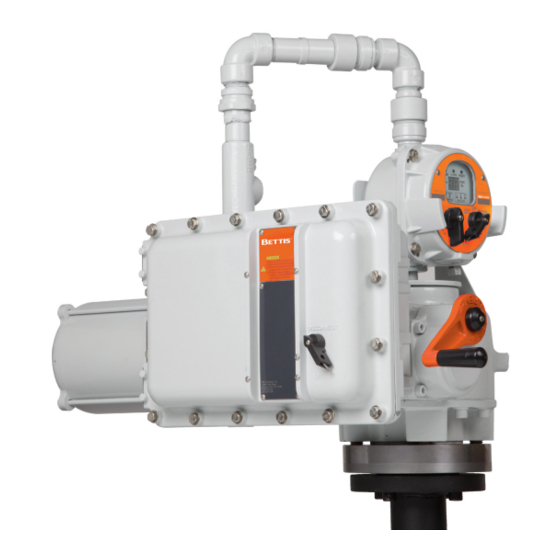
Section 2: Features Installation, Operation and Maintenance Manual MAN-02-10-93-0700-EN Rev. 0 May 2019 Section 2: Features The actuator features several assemblies as shown in Figure 3. Unique features of the actuator are listed below. Figure 3 MPA Features Local Display Module (LDM) Low Voltage with Display &... - Page 8 Section 2: Features Installation, Operation and Maintenance Manual May 2019 MAN-02-10-93-0700-EN Rev. 0 • MPA supports all network protocols available with all other Bettis actuators — Modbus RS485 Bus or E>Net ring available — Profibus Redundancy with Redcom — Foundation Fieldbus —...
- Page 9 Section 2: Features Installation, Operation and Maintenance Manual MAN-02-10-93-0700-EN Rev. 0 May 2019 Figure 4 Local Display Module (LDM) • Remote display module (RDM) option available — RDM displays identical information and performs identical control as LDM — Bettis’s patented combined switch logic allows detection of selector switch position on LDM and RDM —...
-
Page 10: Section 3: Mechanical And Electrical Installation
Section 3: Mechanical and Electrical Installation Installation, Operation and Maintenance Manual May 2019 MAN-02-10-93-0700-EN Rev. 0 Section 3: Mechanical and Electrical Installation Do not connect power until you have gone through the following checklist Does the information given on the nameplate correspond with the application? Have all wire terminations and the equipotential bonding system been connected correctly? EEx d applications: are the cable entries, plugs and adaptors EEx d approved? -
Page 11: Section 4: Wiring
Section 4: Wiring Installation, Operation and Maintenance Manual MAN-02-10-93-0700-EN Rev. 0 May 2019 Section 4: Wiring All user wiring terminations are made inside the Electrical Enclosure shown in Figure 3 on Page 2. Refer to wiring diagram located at the back of this manual for wiring connections. High voltage power connections are made to the disconnect/circuit breaker located inside the electrical enclosure. -
Page 12: Section 5: Local Display Module
Section 5: Local Display Module Installation, Operation and Maintenance Manual May 2019 MAN-02-10-93-0700-EN Rev. 0 Section 5: Local Display Module Description Contains microprocessor controller, position encoder, and network interface. This is the main controller used to setup and operate the actuator. This module displays operating parameters, port position, torque, and alarms. -
Page 13: Operation
Section 5: Local Display Module Installation, Operation and Maintenance Manual MAN-02-10-93-0700-EN Rev. 0 May 2019 Operation Place the “Selector Knob” in the desired operating position. LOCAL – hands on operation at the actuator by manipulation of Control Knob. REMOTE – used within the context of plant operation, i.e. Remote Control Panel, PLC, DCS, etc. -
Page 14: Operational Display
Section 5: Local Display Module Installation, Operation and Maintenance Manual May 2019 MAN-02-10-93-0700-EN Rev. 0 Operational Display Operational indicators for RUN / ALARM / PORT position use long lasting LED’s. Run torque and port position are shown on the digital readout during normal operation. Torque in percent of maximum is displayed as a 2-digit number only while the motor is running. - Page 15 Section 5: Local Display Module Installation, Operation and Maintenance Manual MAN-02-10-93-0700-EN Rev. 0 May 2019 Table 3. Alarm List Alarm Definition Details Lost communication with the Remote Display Module (RDM) Communication Error when configured. Actuator failed to move within 8 seconds after commanded by Stall Alarm either local or remote controls.
-
Page 16: Section 6: Field Setup Using Mpa Config Software
Section 6: Field Setup Using MPA Config Software Installation, Operation and Maintenance Manual May 2019 MAN-02-10-93-0700-EN Rev. 0 Section 6: Field Setup Using MPA Config Software MPA Config is a Windows application for configuration, calibration, test, and operation of the MPA. MPA Config is compatible with Windows XP, Windows 7, and Vista. Connection to the MPA requires a RS485 link. -
Page 17: User Setup Menus
Section 6: Field Setup Using MPA Config Software Installation, Operation and Maintenance Manual MAN-02-10-93-0700-EN Rev. 0 May 2019 If connected to the RDM port, set the computer Baud Rate to 9600, Parity None and Stop Bits to 1. Set the Slave Address to 254. The RDM port configuration of the MPA is fix at 9600,N,8,1, address 254 and may not be changed by the user. - Page 18 Section 6: Field Setup Using MPA Config Software Installation, Operation and Maintenance Manual May 2019 MAN-02-10-93-0700-EN Rev. 0 Figure 10 The Network SetUp changes configuration only for the network ports. It does not affect the RDM port. If a pipeline is not connected to any one or more ports, or if it is desirable to skip any one or more ports, click on the “Delete Port”...
-
Page 19: Selecting New Home Port (Hp Command Using Control Knob Setup)
Section 6: Field Setup Using MPA Config Software Installation, Operation and Maintenance Manual MAN-02-10-93-0700-EN Rev. 0 May 2019 Selecting New Home Port (HP command using Control Knob setup) The User may select any port as the new “Home Port” in the field. When a new home port is selected, the new home port is identified as Port 0 or 8 and the MPA reassigns all other port numbers (1-7) in a counterclockwise sequence around the MPFS. -
Page 20: Home Port Led Function
Section 6: Field Setup Using MPA Config Software Installation, Operation and Maintenance Manual May 2019 MAN-02-10-93-0700-EN Rev. 0 Home Port LED Function The home port LED on the LDM will now identify the newly selected home port position. This LED is on when the actuator is within 0.25 degrees of the selected home port. When the blind cover of the home port is removed in the field to inspect the seals, the home zero may be verified and corrected if an error is detected. -
Page 21: Factory Setup Menus
Section 6: Field Setup Using MPA Config Software Installation, Operation and Maintenance Manual MAN-02-10-93-0700-EN Rev. 0 May 2019 Factory SetUp Menus All factory settings may be viewed but some items in Factory Setup require a Factory Password to change them. The protected items are, RDM Required, Motor Type, Reset User Password, and Calibrate Ports. -
Page 22: Motor Type
Section 6: Field Setup Using MPA Config Software Installation, Operation and Maintenance Manual May 2019 MAN-02-10-93-0700-EN Rev. 0 Motor Type Motor Type is entered at the factory for the type of MPFS, power supply and motor horse power rating as shown in the table below. Motor type is displayed on the MPA Confg Factory Setup Menu for information only and cannot be edited. -
Page 23: Control Screen
Section 6: Field Setup Using MPA Config Software Installation, Operation and Maintenance Manual MAN-02-10-93-0700-EN Rev. 0 May 2019 Control Screen The control screen (see Figure 14) is a valuable tool for commissioning the system. All functions of the system may be tested prior to commissioning with the DCS. This screen may be used to troubleshoot any problems should they occur. -
Page 24: Section 7: Field Setup Using Local Controls
Section 7: Field Setup Using Local Controls Installation, Operation and Maintenance Manual May 2019 MAN-02-10-93-0700-EN Rev. 0 Section 7: Field Setup Using Local Controls Use the Local Control (left) knob and Selector (right) knob to enter setup mode and to execute Setup functions. -
Page 25: Alarm History Display
Section 7: Field Setup Using Local Controls Installation, Operation and Maintenance Manual MAN-02-10-93-0700-EN Rev. 0 May 2019 When the actuator LDM is placed in SETUP mode of operation it first displays the Field Diagnostics (Fd) menu item. The second menu item Alarm History (AH) menu. The field diagnostics and alarm history may be viewed without entering a passcode (See Field Diagnostics and Alarm History Display section). -
Page 26: Setup Mode Display Sequence
Section 7: Field Setup Using Local Controls Installation, Operation and Maintenance Manual May 2019 MAN-02-10-93-0700-EN Rev. 0 Setup Mode Display Sequence The three (3) amber LED’s for the LOR section flash to indicate Setup Mode. When in setup mode, the user must enter the REMOTE(NEXT) or LOCAL(BACK) within 120 seconds or the display will revert back to the normal display mode. - Page 27 Section 7: Field Setup Using Local Controls Installation, Operation and Maintenance Manual MAN-02-10-93-0700-EN Rev. 0 May 2019 Table 6. Setup Mode Parameter Values Menu Parameter Value Units Default Field diagnostics 0-27 Fault code 0=No, Skip to 1st Passcode Display Alarm History? 1=Yes, Display History 1st latest alarm Alarm...
-
Page 28: Section 8: Field Diagnostics
Section 8: Field Diagnostics Installation, Operation and Maintenance Manual May 2019 MAN-02-10-93-0700-EN Rev. 0 Section 8: Field Diagnostics Should trouble occur, the Field Diagnostics feature may be used to help diagnose the problem. Field diagnostics provides more detailed and definitive feedback than the alarms, i.e. -
Page 29: Fd Fault Codes
Section 8: Field Diagnostics Installation, Operation and Maintenance Manual MAN-02-10-93-0700-EN Rev. 0 May 2019 Fd Fault Codes MCP23 Chip will not initialize (pertains to a three phase AC motor type) Motor is wired to turn in the wrong direction Self-detected wiring fault (Emergency Shut Down - LE) Host transmitted ESD command (Emergency Shut Down - LE) Lost Phase, pertains to a three phase AC motor type - PH Motor has over-heated (Motor overload - OL) -
Page 30: Section 9: Remote Network Control
Section 9: Remote Network Control Installation, Operation and Maintenance Manual May 2019 MAN-02-10-93-0700-EN Rev. 0 Section 9: Remote Network Control Modbus RTU The native language of the MPA is Modbus RTU. If other network protocols such as Foun- dation Fieldbus are used, a Communication Adapter Module (CAM) module is installed to translate between the selected protocol and Modbus. - Page 31 Section 9: Remote Network Control Installation, Operation and Maintenance Manual MAN-02-10-93-0700-EN Rev. 0 May 2019 9.1.3 Holding Register Map These are the recommended registers to use. Other registers are active but the user is cautioned not to use the data or write to any other registers. Table 9.
-
Page 32: Foundation Fieldbus (Ff)
Section 9: Remote Network Control Installation, Operation and Maintenance Manual May 2019 MAN-02-10-93-0700-EN Rev. 0 Foundation Fieldbus (FF) The MPA uses a CAM18 to convert between Modbus and Foundation Fieldbus. Refer to M2CP CAM18 & TEC2000 CAM218 Installation, Operation and Instruction Manual for installation and setup of the FF link. - Page 33 Section 9: Remote Network Control Installation, Operation and Maintenance Manual MAN-02-10-93-0700-EN Rev. 0 May 2019 Modbus Foundation Fieldbus Configuration and Calibration Registers MAO (Channel 19) MAI (Channel 20) Register Parameter Parameter Port 0 calibration IN_1 OUT_1 Port 1 calibration IN_2 OUT_2 Port 2 calibration IN_3...
-
Page 34: Profibus Dp Reduntant Networks With Redcom
Section 9: Remote Network Control Installation, Operation and Maintenance Manual May 2019 MAN-02-10-93-0700-EN Rev. 0 Profibus DP Reduntant Networks with Redcom The MPA uses CAM20 to convert between Mosbus RTU and Profibus DP. This section describes the data mapping between the Profibus DP host and MPA Modbus map. The mapping allows the Profibus DP host to control the Flow Selector and monitor the actuator status. -
Page 35: Devicenet
Section 9: Remote Network Control Installation, Operation and Maintenance Manual MAN-02-10-93-0700-EN Rev. 0 May 2019 DeviceNet The MPA uses CAM09 to convert between Modbus and DeviceNet. This section describes the data mapping between the DeviceNet host and MPA Modbus map. The mapping allows the DeviceNet host to control the Flow Selector and monitor actuator status. -
Page 36: Appendix A: Ec Declaration Of Conformity Certificate
Appendix Installation, Operation and Maintenance Manual May 2019 MAN-02-10-93-0700-EN Rev. 0 Appendix A: EC Declaration of Conformity Certificate Appendix... -
Page 37: Appendix B: Wiring Diagrams
Appendix Installation, Operation and Maintenance Manual MAN-02-10-93-0700-EN Rev. 0 May 2019 Appendix B: Wiring Diagrams Three Phase Power Appendix... - Page 38 Appendix Installation, Operation and Maintenance Manual May 2019 MAN-02-10-93-0700-EN Rev. 0 Single Phase Power Appendix...
- Page 39 Appendix Installation, Operation and Maintenance Manual MAN-02-10-93-0700-EN Rev. 0 May 2019 24VDC Power Appendix...
- Page 41 P. R. China Székesfehérvár 8000 T +86 22 8212 3300 Hungary The Emerson logo is a trademark and service mark of Emerson Electric Co. T +36 22 53 09 50 Bettis is a mark of one of the Emerson family of companies.