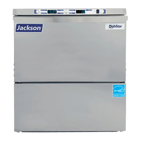
Jackson DISHSTAR Series Installation, Operation And Service Manual
Hide thumbs
Also See for DISHSTAR Series:
- Replacement (3 pages) ,
- Installation, operation and service manual (76 pages)
Table of Contents
Troubleshooting

Related Manuals for Jackson DISHSTAR Series


Summary of Contents for Jackson DISHSTAR Series
- Page 1 INSTALLATION, OPERATION, INSTALLATION, OPERATION, AND SERVICE MANUAL AND SERVICE MANUAL DISHSTAR DISHSTAR SERIES GLASSWASHER DISHMACHINES SERIES GLASSWASHER DISHMACHINES DishStar ADA-SEER Manual • 07610-004-99-71-B...
- Page 2 ONE YEAR LIMITED PARTS AND LABOR WARRANTY For a period of one (1) year from date of original installation of a new Jackson Dishmachine (but in no event to exceed eighteen (18) months from date of shipment from Jackson’s factory), Jackson WWS, Inc. (Jackson) will repair or replace, at its discretion, any original part that proves defective in materials or workmanship at the time the Dishmachine was purchased;...
- Page 3 MANUFACTURER'S LIMITED WARRANTY (CONT.) (APPLICABLE ONLY IN THE UNITED STATES AND CANADA) PRODUCT CHANGES: Jackson reserves the right to make changes in design and specification of any component of the Dishmachine as engineering or necessity requires. DISCLAIMER OF WARRANTIES: THERE ARE NO WARRANTIES, EXPRESSED OR IMPLIED, INCLUDING, WITHOUT LIMITATION, ANY IMPLIED WARRANTY OF FITNESS FOR A PARTICULAR PURPOSE OR MERCHANTABILITY, THAT ARE NOT SET FORTH HEREIN, OR THAT EXTEND BEYOND THE DURATION HEREOF.
- Page 4 REVISION HISTORY Revision Revision Made by Applicable ECNs Details Letter Date 12-13-21 8566 Initial release of the manual. 2-2-22 8709 Updated electical panel, chemical feeder pump assembly, and door interlock.
- Page 5 NOMENCLATURE DishStar ADA-SEER Glasswasher dishmachine; high-temperature, hot-water sanitizing, with a booster tank and detergent and rinse-aid chemical feeder pumps. Equipped with Steam Elimination and Energy Recovery (SEER) system. The manufacturer provides technical support for all of the dishmachines detailed in this manual. We strongly recommend that you refer to this manual before making a call to our technical support...
-
Page 6: Table Of Contents
TABLE OF CONTENTS GUIDES Symbols ............................1 Abbreviations & Acronyms ....................... 1 SPECIFICATIONS Dimensions ............................2 Operating Parameters ........................3 Electrical Requirements ........................4 INSTRUCTIONS Installation Instructions ........................5 Inspection......................... 5 Unpacking ........................5 Plumbing .......................... 5 Water Supply Connections ....................5 Pressure Regulator ...................... - Page 7 TABLE OF CONTENTS MAINTENANCE Preventative Maintenance ......................17 TROUBLESHOOTING Setpoints ............................19 Fault Codes ............................ 21 Troubleshooting ..........................24 PARTS Terminal Block Box ......................... 26 Top Panel ............................27 Electrical Panel ..........................28 Chemical Feeder Pump Assembly ....................30 Door ..............................32 Door Interlock ..........................
-
Page 8: Symbols
GUIDES SYMBOLS - Risk of Injury to Personnel WARNING - Risk of Damage to Equipment CAUTION - Risk of Electrical Shock - Caustic Chemicals - Reference Data Plate - Lockout Electrical Power - Important Note NOTICE - Instructions Hyperlink ABBREVIATIONS &... -
Page 9: Specifications
DIMENSIONS SPECIFICATIONS LEGEND A - Electrical Connection C - Drain Connection All dimensions from the floor (5/8" ID, install into MIN can be increased 1” using the B - Water Inlet (with 5' Hose) 1 1/2" Drain with Air-gap) machine’s adjustable feet. (3/4"... -
Page 10: Operating Parameters
OPERATING PARAMETERS SPECIFICATIONS DishStar ADA-SEER Operating Capacity: Racks per Hour 24 (20)* Dishes per Hour Glasses per Hour Tank Capacity (Gallons): Wash Tank Rinse Tank 1.66 NOTICE Always refer to the machine data plate for specific electrical and water requirements. The material provided on this page is for reference only and is subject to change without notice. -
Page 11: Electrical Requirements
ELECTRICAL REQUIREMENTS SPECIFICATIONS NOTICE DishStar ADA-SEER Electrical Characteristics All electrical ratings provided in this manual are for reference VOLTS only. Always refer to the machine data plate to get exact electrical information for this machine. All electrical work performed on machines should be done in accordance with applicable local, PHASE state, territorial, and national codes. -
Page 12: Instructions
INSTRUCTIONS INSTALLATION INSPECTION Before installing the machine, check packaging and machine for damage. Damaged packaging might be an indication of damage to the machine. If there is any type of damage to both packaging and unit, do not throw away the packaging. The machine Do not throw away has been inspected at the factory before shipping and is expected to arrive in new, packaging if damage is... -
Page 13: Pressure Regulator
INSTRUCTIONS INSTALLATION WATER SUPPLY If water hardness tests at 3 GPG or lower, connect the machine water line (installed at the factory) to the facility water line. A water shut-off valve should be installed in CONNECTIONS: the water line between the facility supply and the machine to allow access for service. WATER HARDNESS The water supply line must be capable of a minimum of 10 PSI “flow”... -
Page 14: Electrical Power Connections
INSTRUCTIONS INSTALLATION ELECTRICAL POWER Electrical and grounding conductors must comply with the applicable portions of the National Electric Code ANSI/NFPA 70 (latest edition) and/or other electrical codes. CONNECTIONS The data plate is located on the left-front of the dishmachine. Refer to the data plate for machine operating requirements, machine voltage, total amperage, and serial number. -
Page 15: Chemical Connections
INSTRUCTIONS INSTALLATION CHEMICAL This machine is supplied with detergent and rinse-aid pumps and all necessary tubing. To connect, simply locate the chemical tubes and place the ends (with tube CONNECTIONS stiffeners) in the appropriate chemical containers (red for detergent and blue for rinse-aid). -
Page 16: Priming Chemical Feeder Pumps
INSTRUCTIONS INSTALLATION PRIMING CHEMICAL Chemical feeder pumps need priming when the machine is first installed or if the chemical lines have been removed and air was allowed to enter. FEEDER PUMPS CAUTION! Water must be in the sump and wash tank before dispensing chemicals. 1. -
Page 17: Operating Instructions
OPERATING INSTRUCTIONS OPERATION PREPARATION 1. Verify strainers are in place and clean. CAUTION CAUTION! Preparation section must be followed before operating machine! 2. Ensure wash and rinse arms are screwed securely in place and end-caps are tight. 3. Verify wash and rinse arms rotate freely. 4. -
Page 18: Filling The Wash Tub
OPERATING INSTRUCTIONS OPERATION FILLING THE 1. Close door. WASH TUB 2. Press power button. LED ring on power button will turn red. ° 1 1 0 3. Machine will start filling automatically. 4. Wait until wash temperature on display reaches a minimum of 155 °F. Temperature shown is °... -
Page 19: Operational Inspection
OPERATING INSTRUCTIONS OPERATION WASHING A RACK 5. Choose cycle. OF WARE ° Normal is the default cycle. If Heavy or Extra Heavy is chosen, Normal Heavy Extra Heavy the machine will 145 Seconds 213 Seconds 313 Seconds Normally-soiled Ware Heavily-soiled Ware Extremely-soiled Ware stay in that cycle until another is chosen. -
Page 20: Shutdown & Cleaning
OPERATING INSTRUCTIONS OPERATION SHUTDOWN & 1. Close door and turn the machine off by pushing power button. CLEANING 2. Drain valve will activate and empty the machine of water. 3. When draining stops, remove and clean strainers and set aside. CAUTION CAUTION! Do NOT beat strainers to remove... - Page 21 OPERATING INSTRUCTIONS OPERATION SHUTDOWN & 6. Replace end-caps and use a screwdriver to ensure they are tight. CLEANING Use a screwdriver to ensure end-caps are tight. 7. Ensure float (located under left strainer) is free of debris. 8. Spray or wipe out interior of the machine. 9.
-
Page 22: Deliming
OPERATING INSTRUCTIONS OPERATION DELIMING To maintain the machine at its optimum performance level, lime and corrosion deposits must be removed. The frequency for deliming will be based on water conditions. A deliming solution is available from your chemical supplier. Read and follow all instructions on the label. -
Page 23: Detergent Control
OPERATING INSTRUCTIONS OPERATION DETERGENT Detergent usage and water hardness are two factors that greatly contribute to the machine's operating efficiency. Using the proper amount of detergent can become a CONTROL source of substantial savings. A qualified water-treatment specialist can determine what is needed for maximum efficiency from the detergent. -
Page 24: Preventative Maintenance
(230 V) DELAI FUSIBLE DE TYPE TEMPS OU LA PROTECTION CONTRE LES SURINTENSITES. MINIMUM CIRCUIT AMPACITY @208 VOLTS: 27.9 AMPS @230 VOLTS: 30.0 AMPS Jackson WWS, Inc Made in the USA 6209 N US HWY 25E MAXIMUM OVERCURRENT PROTECTION @208 VOLTS: 30 AMPS... - Page 25 PREVENTATIVE MAINTENANCE MAINTENANCE PREVENTATIVE 5. Do not overfill racks. MAINTENANCE 6. Ensure glasses are placed upside-down in rack. 7. Ensure all chemicals being injected into the machine have been verified at correct concentrations. 8. Clean the machine at end of every workday (see Shutdown and Cleaning section).
-
Page 26: Troubleshooting
SETPOINTS TROUBLESHOOTING ADJUSTING To access setpoints, the machine should be on and not in cycle. WASH TEMP 1. Push and hold cycle button for a minimum of six seconds. Wash temperature SETPOINT shows on left display and will flash on and off. °... - Page 27 SETPOINTS TROUBLESHOOTING ADJUSTING 3. Once desired temperature is selected, press and hold cycle button for a minimum of three seconds and no more than six seconds (after three seconds RINSE TEMP rinse temperature will stop flashing). Release cycle button to accept and move SETPOINT to next setting (temperature scale).
-
Page 28: Fault Codes
FAULT CODES TROUBLESHOOTING DISPLAY SHOWS POSSIBLE CAUSES REMEDY 1. Verify incoming water pressure is 10 ± 2 PSI. 1. Low or no water pressure. 2. Verify that fill relay is supplying voltage to fill solenoid. Replace faulty component. 2. Faulty inlet valve or fill relay. 3. - Page 29 FAULT CODES TROUBLESHOOTING DISPLAY SHOWS POSSIBLE CAUSES REMEDY 1. Verify incoming water pressure is 10 ± 2 PSI. 1. Low or no water pressure. 2. Verify that fill relay is supplying voltage to fill solenoid. 2. Faulty inlet valve or fill relay. Replace faulty component.
- Page 30 FAULT CODES TROUBLESHOOTING DISPLAY SHOWS POSSIBLE CAUSES REMEDY "F12 Service needed," "Check booster Faulty temperature probe (T3). Replace probe that connects to P13. thermostat" 1. Fully disconnect 6-pin cable at each end, and reconnect 1. Loose connection in 6-pin cable between each end until a click is heard.
-
Page 31: Troubleshooting
TROUBLESHOOTING TROUBLESHOOTING WARNING! Inspection, testing, and repair of electrical equipment should only be performed by qualified service personnel. Certain procedures in this section require electrical tests or measurements while power is applied to the machine. Exercise extreme caution at all times. If test points are not easily accessible, disconnect WARNING power, attach test equipment, and reapply power to test. - Page 32 TROUBLESHOOTING TROUBLESHOOTING WARNING! Inspection, testing, and repair of electrical equipment should only be performed by qualified service personnel. Certain procedures in this section require electrical tests or measurements while power is applied to the machine. Exercise extreme caution at all times. If test points are not easily accessible, disconnect WARNING power, attach test equipment, and reapply power to test.
-
Page 33: Parts
TERMINAL BLOCK BOX PARTS ITEM DESCRIPTION PART NUMBER Power Connection Decal 09905-011-47-35 Terminal Block Box 05700-004-36-47 Terminal Box Cover (not shown) 05700-003-27-70 Strain Relief 05975-003-37-56 Terminal Block Track 05700-000-43-60 Terminal Block 05940-500-02-19 Locknut, 10-24 Hex with Nylon Insert 05310-373-01-00 Decal, L1, N 09905-011-62-72 Ground Lug 05940-200-76-00... -
Page 34: Top Panel
TOP PANEL PARTS Complete Top Panel Assembly 05700-004-94-13 ITEM DESCRIPTION PART NUMBER Power Button 05930-004-85-60 Start Button 05930-004-96-58 LED Display 05945-004-85-61 Top Panel 05700-004-94-11 Top Control Decal 09905-004-94-08 Cycle Button 05700-003-14-91 Prime Switch 05930-004-97-47 07610-004-99-71-B... -
Page 35: Electrical Panel
ELECTRICAL PANEL PARTS Complete Electrical Panel Assembly 05700-005-00-22 07610-004-99-71-B... - Page 36 ELECTRICAL PANEL PARTS ITEM DESCRIPTION PART NUMBER Contactor, 30 A 240 V 05945-002-74-20 Relay 05945-111-89-75 Soft Start 05945-004-55-75 I/O Module 05945-004-47-81 Dinrail, 5 3/4” 05700-021-72-75 Terminal Block 05999-004-90-68 Separator, Terminal Block 05999-004-90-67 End Bracket, Terminal 05999-004-90-66 Jumper Bars, 3-pole 05999-004-90-71 Tag, Marking 05999-004-90-72 Holder, 6-pole Fuse...
-
Page 37: Chemical Feeder Pump Assembly
CHEMICAL FEEDER PUMP ASSEMBLY PARTS Complete Chemical Feeder Pump Assembly 05700-005-00-23 07610-004-99-71-B... - Page 38 CHEMICAL FEEDER PUMP ASSEMBLY PARTS ITEM DESCRIPTION PART NUMBER Motor, Peri-pump, 14 RPM 04320-011-63-33 Pump Cover, Clear 04320-004-59-45 Pump Housing, Clear 04320-004-59-41 Tube, 8" 04320-004-59-44 Screw, 6-32 x 3/4" 05305-011-37-05 Screw, 8-32 x 1/2" 05305-011-37-06 Screw, 8-32 x 3/8" 05305-011-37-07 Washer, Thrust 04320-004-75-85 Roller, Red Dot...
-
Page 39: Door
DOOR PARTS Complete Door Assembly 05700-004-94-14 07610-004-99-71-B... - Page 40 DOOR PARTS ITEM DESCRIPTION PART NUMBER Outer Door Weldment 05700-004-94-15 Spacer, Hinge 05700-003-33-42 Hinge, Right 05700-003-32-72 Hinge, Left 05700-003-32-71 Baffle, Door 05700-003-33-38 Inner Door 05700-004-94-18 Fastener, 10-32 05340-111-58-10 Stop, Door Hinge 05700-003-32-55 Retaining Plate 05700-011-44-37 Screw, 10-32 x 1/4" 05305-173-01-00 Gasket, Door 20"...
-
Page 41: Door Interlock
DOOR INTERLOCK PARTS Complete Door Interlock Assembly 05700-004-99-57 07610-004-99-71-B... - Page 42 DOOR INTERLOCK PARTS ITEM DESCRIPTION PART NUMBER Screw, 6-32 x 5/8" 05305-011-39-85 Locknut, 6-32 with Nylon Insert 05310-373-03-00 Link, Interlock Connector 05700-004-71-37 Pin, Interlock 05700-004-71-49 Switch, Interlock 05930-004-71-36 Gear Motor 06105-004-70-04 Interlock Guide 05700-004-71-50 Interlock Cam 05700-004-71-39 Screw, Shoulder, 10-32 x 1/4" 05305-004-71-40 Relay, 10 A, 220 V AC 05945-004-84-93...
-
Page 43: Miscellaneous Door Components
MISCELLANEOUS DOOR COMPONENTS PARTS Parts are not shown to scale in relation to each other. ITEM DESCRIPTION PART NUMBER Switch Mounting Plate Assembly 05700-003-33-54 Door Spring 05700-003-32-85 Cover, Left Hinge Weldment 05700-004-36-80 Cover, Right Hinge Weldment 05700-004-36-81 Hinges secured with Locknut, 1/4-20 Hex with Nylon Insert 05310-374-01-00 O-ring 05330-003-32-34... -
Page 44: Wash & Motor
WASH & MOTOR PARTS 07610-004-99-71-B... - Page 45 WASH & MOTOR PARTS ITEM DESCRIPTION PART NUMBER Wash Arm Assembly 05700-021-39-23 Motor Support 05700-004-53-96 Wash Halo 05700-004-42-21 Pipe Clamp 05700-000-35-06 Wash Arm End-cap 05700-003-31-59 Gasket, Manifold 05330-003-75-91 Hose, 5/8" ID, Blue Silicone 05700-004-53-99 Gasket, Wash Hub 05330-002-34-77 Wash Hub 05700-004-43-04 Pump and Motor 06105-004-50-75...
-
Page 46: Rinse Manifold
RINSE MANIFOLD PARTS Rinse Arm Bearing Kit 06401-004-57-50 ITEM DESCRIPTION PART NUMBER Complete Rinse Manifold Assembly 05700-004-52-44 Pipe Clamp 05700-000-35-06 Rinse Arm End-cap (includes o-ring) 05700-004-34-62 Complete Rinse Arm Assembly 05700-004-39-39 Rinse Arm 05700-004-38-75 Bearing Assembly, Rinse Arm 05700-004-54-71 O-ring (included in item #5) 05330-002-60-69 Retaining Ring 05340-112-01-11... -
Page 47: Plumbing
PLUMBING PARTS Complete SEER Plumbing Assembly 05700-004-63-78 CONNECTS TO COLD WATER INLET ON SEER SYSTEM CONNECTS TO HOT WATER OUTLET ON SEER SYSTEM *Item not included in part number of complete SEER plumbing assembly and must be ordered separately. 07610-004-99-71-B... - Page 48 PLUMBING PARTS ITEM DESCRIPTION PART NUMBER Inlet Plumbing Assembly 05700-004-53-98 Pressure Regulating Valve Assembly, Dial-set 05700-004-94-35 Booster Tank Discharge Assembly 05700-004-55-97 Tee, 1/2" Brass 04730-211-27-00 Nipple, 1/2" Close Brass 04730-207-15-00 Water Hammer Arrestor, 1/2" 04730-004-58-56 SEER Inlet Plumbing Assembly 05700-004-60-46 Elbow, 90-degree, 1/2"...
-
Page 49: Rinse Plumbing
RINSE PLUMBING PARTS Complete Rinse Plumbing Assembly 05700-004-61-32 07610-004-99-71-B... - Page 50 RINSE PLUMBING PARTS ITEM DESCRIPTION PART NUMBER Vacuum Breaker, 1/2" Brass 04820-003-06-13 Hose, 1/2" ID, 14" 05700-004-99-89 Nipple, 1/2" x 3", Brass 04730-004-20-10 Elbow, 1/2", 90-degree, Brass 04730-011-42-96 Elbow, 90-degree 04730-406-32-01 Pipe, 3", Copper 05700-001-05-21 Adapter, 1/2" 04730-002-64-68 Complete Rinse Injector Assembly 05700-004-43-86 Rinse Injector Only 09515-004-22-73...
-
Page 51: Scale Prevention System
SCALE PREVENTION SYSTEM PARTS SCALE PREVENTION SYSTEM (SPS) OPTION 04730-003-28-03 NOTICE Must be installed vertically. The provided bracket is secured to the wall. Observe proper inlet/outlet water directions (flow directions are molded into the top of the head). Line pressure should be released before changing cartridges. -
Page 52: Rinse Tank
RINSE TANK PARTS Front of Rinse Tank Back of Rinse Tank 07610-004-99-71-B... - Page 53 RINSE TANK PARTS ITEM DESCRIPTION PART NUMBER Rinse Tank 05700-004-41-88 Heater Gasket 05330-011-47-79 Rinse Heater, 5.45 kW, 208-230 V 04540-004-45-12 Lockwasher, Split 5/16" 05311-275-01-00 Nut, Hex 5/16-18 05310-275-01-00 Cable, Temperature Probe 05700-004-33-23 Thermistor Probe, 4" with 18" Cable 06685-004-34-58 Fitting, 1/4", Brass Nut/Sleeve 05310-924-02-05 Plug, 1/4"...
-
Page 54: Seer System
SEER SYSTEM PARTS Complete SEER System Assembly 05700-004-63-06 07610-004-99-71-B... - Page 55 SEER SYSTEM PARTS ITEM DESCRIPTION PART NUMBER Motor, Fan 05999-004-63-31 Wheel, Blower 05999-004-59-13 Bracket, Bearing Boot 05700-004-50-94 Bushing and Housing Assembly 03120-004-50-88 Locknut, 10-24 Hex with Nylon Insert 05310-373-01-00 Bracket, Motor Adjustment 05700-004-58-81 Grommet, Push-in, 3/4" ID 05330-004-59-14 Bracket, Enclosure Filler Plate 05700-004-58-93 Diversion Plate 05700-004-59-04...
-
Page 56: Tub & Frame
TUB & FRAME PARTS DETAIL A 07610-004-99-71-B... - Page 57 TUB & FRAME PARTS ITEM DESCRIPTION PART NUMBER Panel,Top 05700-004-94-13 Shroud, Left 05700-004-55-00 Hinge Cover, Left 05700-002-18-41 Hinge Stop, Left 05700-003-32-61 Door Spring 05700-003-32-85 Strainer 05700-004-09-43 Panel, Kick 05700-004-94-07 Hinge Cover, Right 05700-004-22-66 Door Interlock Assembly See Door Interlock page. Foot, Adjustable 05340-002-71-71 Shroud, Right...
-
Page 58: Miscellaneous Parts
MISCELLANEOUS PARTS PARTS Parts are not shown to scale in relation to each other. Drain Water Tempering Kit Install Instructions ITEM DESCRIPTION PART NUMBER Rail, Left Rack 05700-031-37-88 Rail, Right Rack 05700-031-37-88 Splash Shield 05700-003-33-51 Dual Float Switch 06680-004-48-53 Drain Water Tempering Kit 06401-004-59-11 07610-004-99-71-B... -
Page 59: Schematics
208/230 V, 50/60 HZ, 1-PHASE SCHEMATICS 07610-004-99-71-B... - Page 60 Jackson WWS, Inc. • 6209 N. US Hwy 25E • Gray, KY 40734 USA 1.888.800.5672 • www.jacksonwws.com DishStar ADA-SEER Manual • 07610-004-99-71-B...