Table of Contents
Advertisement
Quick Links
Installation, Operation,
and Maintenance
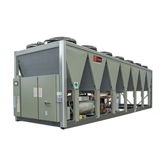
Sintesis™ Air-Cooled Chillers
Model RTAF
Only qualified personnel should install and service the equipment. The installation, starting up, and servicing
of heating, ventilating, and air-conditioning equipment can be hazardous and requires specific knowledge and
training. Improperly installed, adjusted or altered equipment by an unqualified person could result in death or
serious injury. When working on the equipment, observe all precautions in the literature and on the tags,
stickers, and labels that are attached to the equipment.
June 2015
SAFETY WARNING
RTAF-SVX001A-EN
Advertisement
Table of Contents

Related Manuals for Trane Sintesis RTAF


Summary of Contents for Trane Sintesis RTAF
- Page 1 Installation, Operation, and Maintenance Sintesis™ Air-Cooled Chillers Model RTAF SAFETY WARNING Only qualified personnel should install and service the equipment. The installation, starting up, and servicing of heating, ventilating, and air-conditioning equipment can be hazardous and requires specific knowledge and training.
-
Page 2: Introduction
NEVER PERFORM ANY Practices SWITCHING, DISCONNECTING, OR VOLTAGE TESTING WITHOUT PROPER ELECTRICAL PPE AND Trane believes that responsible refrigerant practices are ARC FLASH CLOTHING. ENSURE ELECTRICAL important to the environment, our customers, and the air METERS AND EQUIPMENT ARE PROPERLY RATED conditioning industry. -
Page 3: Copyright
Copyright This document and the information in it are the property of Trane, and may not be used or reproduced in whole or in part without written permission.Trane reserves the right to revise this publication at any time, and to make changes to its content without obligation to notify any person of such revision or change. -
Page 4: Table Of Contents
Table of Contents Introduction Water Treatment ....18 ......2 Warnings, Cautions, and Notices . - Page 5 Table of Contents Refrigerant Cycle ..... 33 Running (Lag Compressor/Circuit Start and Run) ......56 Refrigerant and Oil .
-
Page 6: Model Number Description
Identifies unit electrical requirements. • Compressor model number. See “Compressor Model • Lists correct operating charges of R-134a and Number, ” p. refrigerant oil (Trane OIL00311). • Compressor serial number. See “Compressor Serial • Lists unit test pressures. Number, ” p. -
Page 7: Model Number Descriptions
Factory Installed - Water Limit Setpoint 45 cm/s Location Percent Capacity Digit 22 — Insulation Percent Capacity and Leaving Trane Commercial Systems, Water and Demand Limit Pueblo, CO USA Factory Insulation Setpoint All Cold Parts 0.75” Digits 10, 11— Design Sequence Percent Capacity and Digit 23 —... -
Page 8: Compressor Model Number
Model Number Descriptions Compressor Model Number Digits 1-3 — Compressor Family CHH= Positive displacement, refrigerant, helical rotary, hermetic compressor Digit 4— Compressor Type GP2+ Digit 5 All compressors Digit 6 — Frame Size K Frame L Frame M Frame N Frame Digit 7 —... -
Page 9: General Information
General Information The Sintesis RTAF units are helical-rotary type, air-cooled chillers designed for outdoor installation.The refrigerant circuits are factory-piped, leak tested and dehydrated. Every unit is electrically tested for proper control operation before shipment. Chilled water inlet and outlet openings are covered for shipment.The Sintesis RTAF featuresTrane’s exclusive... -
Page 10: General Data
Refrigerant Charge (ckt 1/ckt 2) 134.3/129.4 134.7/129.8 84.9 84.9 99.0 99.0 96.3 39.2/38.5 39.3/38.5 46.0/44.9 50.4/44.9 49.5/43.7 60.9/58.7 61.1/59.0 Trane Oil 00311 (bulk)/OIL00315 (1 gal)/OIL00317 (5 gal) Oil Charge/ckt 1.53 1.56 1.56 1.56 1.64 1.96 2.01 (a) Nominal tonnage at 60 Hz. RTAF-SVX001A-EN... -
Page 11: Pre-Installation
Pre-Installation Inspection When the unit is delivered, verify that it is the correct unit and that it is properly equipped. Inspect all exterior components for visible damage. Report any apparent damage or material shortage to the carrier and make a “unit damage” notation on the carrier’s delivery receipt. -
Page 12: Installation Requirements
(a) Start-up must be performed by Trane or an agent of Trane specifically authorized to perform start-up and warranty of Trane products. Contractor shall provide Trane (or an agent of Trane specifically authorized to perform start-up) with notice of the scheduled start-up at least two weeks prior to the scheduled start-up. -
Page 13: Dimensions And Weights
Dimensions and Weights Service Clearance Figure 2. RTAF service clearances Notes: • Area above unit required for operation, maintenance, replacement is shown (right side of unit, as facing panel access and airflow. control panel). However, either side is acceptable. NO OBSTRUCTIONS ABOVE UNIT •... -
Page 14: Installation Mechanical
Installation Mechanical Location Requirements Lifting and Moving Instructions Sound Considerations WARNING Heavy Objects! • Locate the unit away from sound-sensitive areas. Failure to follow instructions below or properly lift unit • Install the optional elastomeric isolators under the could result in unit dropping and possibly crushing unit. -
Page 15: Center Of Gravity
Installation Mechanical Center of Gravity Figure 5. Lifting configuration — 4 point Figure 6. Center of gravity 96” (2438mm) Spreader Bar Lifting Location 2 (Lifting location 3 located on other side of unit) Lifting Location 1 Control (Lifting location 4 Panel located on other side of unit) Table 5. -
Page 16: Isolation And Sound Emission
Installation Mechanical Isolation and Sound Emission Figure 7. Elastomeric isolator The most effective form of isolation is to locate the unit 6.25 away from any sound sensitive area. Structurally 1/2 - 13NC - 2B transmitted sound can be reduced by elastomeric vibration eliminators. - Page 17 Installation Mechanical Table 7. Point weights Location Tons 1567 1601 1496 1530 1589 1623 1517 1551 2342 1062 2386 1082 1420 1445 1009 1025 2294 1041 2332 1058 1557 1586 2169 2658 1206 1621 1489 1077 2189 2162 1734 1702 2303 1045 2159...
-
Page 18: Chilled Water Piping Recommendations
Install shutoff valves on both the entering and treatment specialist be engaged to determine what leaving water lines so that the evaporator can be isolated water treatment, if any, is required. Trane assumes no responsibility for equipment failures which result from for service. -
Page 19: Entering Chilled Water Piping
Installation Mechanical Figure 9. Evaporator water piping Bypass Valve Pressure Gauge Isolation Valve Water Flow Switch Vibration Isolators Evaporator Water Inlet Temperature Sensor Evaporator - End View (2-pass) Evaporator Water Outlet Temperature Sensor Evaporator Waterbox Isolate unit for initial water loop cleaning Vent Vent must be installed at the high point of the line Strainer... -
Page 20: Evaporator Flow Switch
Installation Mechanical potential for hydrostatic pressure buildup on a water • A minimum distance of 5x pipe diameter must be temperature increase. Refer to applicable local codes for maintained between flow switch and any bends, relief valve installation. valves, changes in cross sections, etc. Figure 10. -
Page 21: Evaporator Waterside
Installation Mechanical Evaporator Waterside Pressure Drop Curves Figure 11. Evaporator water pressure drop — 2-pass without turbulators 215T 200T 180T 170T 150T 130T 115T 1000 Water Flow (GPM) RTAF-SVX001A-EN... - Page 22 Installation Mechanical Figure 12. Evaporator water pressure drop — 2-pass with turbulators 88.0 215T 80.0 200T 180T 72.0 170T 64.0 150T 56.0 130T 48.0 115T 40.0 32.0 24.0 16.0 1000 Water Flow (GPM) RTAF-SVX001A-EN...
-
Page 23: Freeze Avoidance
Installation Mechanical Freeze Avoidance One or more of the ambient freeze avoidance methods in Table 9 must be used to protect the Sintesis™ chiller from ambient freeze damage. Table 9. RTAF freeze avoidance methods Protects to ambient Method temperature Notes •... -
Page 24: Low Evaporator Refrigerant Cutout And Glycol Requirements
Installation Mechanical Low Evaporator Refrigerant Cutout and Glycol Requirements The table below shows the low evaporator temperature Note: Table below should not be interpreted as cutout for different glycol levels. Additional glycol beyond suggesting operating ability or performance what is required for freeze protection will adversely effect characteristics at all tabulated glycol percentages. -
Page 25: Installation Electrical
For variable frequency drives or other energy storing components provided by Trane or All units are factory-connected for appropriate labeled others, refer to the appropriate manufacturer’s literature voltages. - Page 26 Installation Electrical Chilled Water Pump Control In general, when there is either a non-latching or latching diagnostic, the EWP relay is turned off as though there was a zero time delay. Exceptions whereby the relay continues NOTICE: to be energized occur with: Equipment Damage! •...
-
Page 27: Programmable Relays
Installation Electrical Programmable Relays Table 12. Alarm and status relay output configuration Description A programmable relay concept provides for enunciation of This relay output is energized any time either certain events or states of the chiller, selected from a list of the Low Evaporator Water Temperature –... -
Page 28: Low Voltage Wiring
Installation Electrical Low Voltage Wiring Communicated input (Tracer) to initiate and command the Ice Building mode. The remote devices described below require low voltage UC800 also provides a “Front Panel IceTermination wiring. All wiring to and from these remote input devices Setpoint”... -
Page 29: External Demand Limit Setpoint (Edls) Option
Installation Electrical mA each correspond to a 10 to 65°F (-12 to 18°C) external field installation, or can be used to enable or disable the chilled water setpoint. feature (if installed). The following relationships exist: EDLS and ECWS Analog Input Signal Wiring Details: Voltage Signal External Water Setpoint... -
Page 30: Afd Drive
MAXIMUM RESET is a user adjustable limit providing the • Unit Mounted with factory pre-wiring maximum amount of reset. For all types of reset, CWS' - • ‘Trane Drive Utility’ for configuration and tracking CWS < or = Maximum Reset. See Service Manual BAS-SVM01*-EN for more information. Range... -
Page 31: Afd Drive Installation
Installation Electrical AFD Drive Installation Table 14. Non-compressor specific parameter settings Description Setting The AFD drive is manufactured with a jumper installed 1-24 Motor Current Table 15 between terminal 12 (+24Vdc source) and terminal 37 (Safe Stop digital input).This jumper must be removed 1-25 Motor Nominal Speed Table 15... -
Page 32: Communication Interfaces
Installation Electrical Table 15. Compressor-specific parameter settings 115 to 215 tons — 60Hz Parameters Description 460V 380V 575V 460V 380V 575V 460V 380V 575V 460V 380V 575V 460V 380V 575V 1-21 Motor Power (hp) 1-22 Motor Voltage (V) 460V 380V 575V 460V 380V... -
Page 33: Operating Principles
The Sintesis™ chiller uses environmentally friendly electronic expansion valve. Fully modulating compressor refrigerants.Trane believes that responsible refrigerant and electronic expansion valve provide variable capacity practices are important to the environment, our modulation over the entire operating range. -
Page 34: Evaporator
Operating Principles All condenser fan motors are designed with permanently lubricated ball bearings and internal temperature and current overload protection. Evaporator The evaporator is a tube-in-shell heat exchanger design constructed from carbon steel shells and tubesheets with internally and externally finned seamless copper tubes mechanically expanded into the tube sheets.The evaporator is designed, tested and stamped in accordance with the ASME Boiler and Pressure Vessel Code for a... -
Page 35: Controls
Controls Overview UC800 Specifications Sintesis™ RTAF chillers utilize the following control/ This section covers information pertaining to the UC800 interface components: controller hardware. • Tracer™ UC800 Controller Wiring and Port Descriptions • Tracer AdaptiView™TD7 Operator Interface Figure 16 illustrates the UC800 controller ports, LEDs, rotary switches, and wiring terminals.The numbered list following Figure 16... -
Page 36: Communication Interfaces
Controls Communication Interfaces Table 16. LED behavior There are four connections on the UC800 that support the communication interfaces listed. See Figure 16, p. 35 UC800 Status the locations of each of these ports. Powered. If the Marquee LED is green solid, the UC800 is powered and no problems exist. -
Page 37: Viewing Chiller Operating Modes
Controls Home screen: Chiller status information Note: You can also access the Chiller Operating Modes screen from the chiller status button in the upper The home screen (Table 19) provides the most frequently left corner of the screen. needed chiller status information on “touch targets” (the entire white rectangular areas) for each chiller component. - Page 38 Controls Table 18. Operating modes (continued) Chiller Modes Description Starting is Inhibited by External The chiller is inhibited from starting or running by the “external stop” hardwired input. Source Power Up Delay Inhibit: min:sec On power up, the chiller will wait for the Power Up Delay Timer to expire. The chiller is currently being inhibited from starting (and running), but may be allowed to start Run Inhibit if the inhibiting or diagnostic condition is cleared.
-
Page 39: Alarms
Controls Table 18. Operating modes (continued) Chiller Modes Description The chiller is still running but shutdown is imminent. The chiller is going through a compressor Shutting Down run-unload or extended operational pumpdown of the lag circuit/compressor (or all circuits simultaneously). Evaporator Water Pump Off Delay The evaporator water pump is continuing to run past the shutdown of the compressors, executing the pump min:sec... - Page 40 Controls • Log Sheet Figure 23. Edit custom report screen • ASHRAE Chiller Log Each button links to the report named on the button. Figure 22. Report screen Figure 24. Report evaporator screen The Reports tab allows a user to select from a list of reports headings.
- Page 41 Controls Table 21. Report compressor screen items Figure 25. Report condenser screen Description Resolution Units Compressor Running Time XX:XX Hr:Min Oil Loss Level Sensor Wet, Dry Text Discharge Temperature °F / °C Discharge Temperature °F / °C Compressor Oil Pressure XXX.X PSIA/kPaA Evaporator Refrigerant Pressure...
-
Page 42: Equipment Settings
Controls Viewing and Changing Equipment Settings Table 22. Report motor screen items Each button in the Equipment Settings column on the Settings screen takes you to a menu screen that contains Description Resolution Units a group of buttons. Each button displays the name of a Active Current Limit Setpoint %RLA setting and its current value... - Page 43 Controls Table 23. Settings screen items Figure 30. Chilled water setpoint screen Description Resolution Units Chiller Settings Active Chilled Water Setpoint ± XXX.X °F / °C Active Current Limit Setpoint XXX% %RLA Active Panel Base Load Cmd On/Auto Text Active Base Loading Setpoint Active Base Loading Command On/Auto Text...
-
Page 44: Display Settings
Controls Display Settings Figure 33. Date format page You can use theTracer AdaptiView display to change the format of the information that appears on the display, and to clean the touch screen. Viewing the Settings Screen Touch the Settings button in the main menu area (Figure 28, p. -
Page 45: Cleaning The Display
Controls To change the date or time: Figure 34. Language page 1. Touch the square presenting the attribute you want to change.The square becomes highlighted. 2. Touch the up or down arrow key on the screen until the your desired selection appears. Repeat the process for any other attributes you want to change. - Page 46 Controls 3. Touch Save.The Settings screen appears with only the 2. Use the keypad to enter your PIN. Security button visible.The Log in/Logout button is a. The PIN is a four-digit number, which was gone. configured for your system with theTracerTU To enable security: service tool.
-
Page 47: Tracer Tu
® adequately service Sintesis chillers,Tracer TU service • 1 GB RAM (minimum) tool is required. (Non-Trane personnel, contact your local • 1024 x 768 screen resolution Trane office for software purchase information.)TracerTU • CD-ROM drive adds a level of sophistication that improves service technician effectiveness and minimizes chiller downtime. -
Page 48: Pre-Start
Pre-Start Upon completion of installation, complete the Sintesis™ RTAF Installation Completion Check Sheet and Request for Trane Service checklist in chapter “Log and Check Sheets, ” Important: Start-up must be performed byTrane or an agent ofTrane specifically authorized to perform start-up and warranty ofTrane products. -
Page 49: Start-Up And Shutdown
“OPEN” position. unit operating pressures. If chiller is limited by any limiting conditions, contact local NOTICE: Trane service organization for more information. Equipment Damage! Temporary Shutdown And Lock the disconnect in the “OPEN” position to prevent accidental start-up and damage to the system when it Restart has been shut down for extended periods. -
Page 50: Seasonal Unit Start-Up Procedure
3. Close the vents in the evaporator chilled water circuits. engaged to determine what water treatment, if any, is required. Trane assumes no responsibility for 4. Open all the valves in the evaporator chilled water equipment failures which result from untreated or circuits. -
Page 51: Sequence Of Operation
Start-Up and Shutdown Sequence of Operation This section will provide basic information on chiller • The text in the circles is the visible top level operating operation for common events. With microelectronic modes that are displayed onTracer™ AdaptiView. controls, ladder diagrams cannot show today’s complex •... -
Page 52: Power Up Diagram
Start-Up and Shutdown Power Up Diagram Figure 43, p. 52 shows the respectiveTD-7 AdaptiView independent of the last mode. If the last mode before screens during a power up of the UC800 and display.This power down was 'Auto', the transition from 'Stopped' to process takes 25 seconds for the UC800 and 90 seconds for 'Starting' occurs, but it is not apparent to the user. -
Page 53: Power Up To Starting
Start-Up and Shutdown Power Up to Starting Figure 44, p. 53 diagram shows the timing from a power • Need to cool (differential to start) already exists up event to energizing the first compressor.The shortest • Oil level is detected immediately allowable time would be under the following conditions: The above conditions would allow for a minimum power •... -
Page 54: Stopped To Starting
Start-Up and Shutdown Stopped to Starting Figure 45 shows the timing from a stopped mode to • Evaporator Water flow occurs quickly with pump on energizing the first compressor.The shortest allowable command time would be under the following conditions: • Need to cool (differential to start) already exists •... -
Page 55: Running (Lead Compressor/Circuit Start And Run)
Start-Up and Shutdown Running (Lead Compressor/Circuit Start and Run) Figure 46 shows a typical start and run sequence for the lead compressor and its circuit. Figure 46. Sequence of operation: running (lead compressor/circuit start nd run) RTAF-SVX001A-EN... -
Page 56: Running (Lag Compressor/Circuit Start And Run)
Start-Up and Shutdown Running (Lag Compressor/Circuit Start and Run) Figure 47 shows a typical start and run sequence for the lag compressor and its circuit. Figure 47. Sequence of operation: running (lag compressor/circuit start nd run) RTAF-SVX001A-EN... -
Page 57: Satisfied Setpoint
Start-Up and Shutdown Satisfied Setpoint Figure 48 shows the normal transition from Running to shutting down due to the Evap Leaving water temp falling below the differential to stop setpoint. Figure 48. Sequence of events: satisfied setpoint RTAF-SVX001A-EN... -
Page 58: Normal Shutdown To Stopped Or Run Inhibit
Start-Up and Shutdown Normal Shutdown to Stopped or Run Inhibit Figure 49 shows theTransition from Running through a attempt to show the final mode if you enter the stop via Normal (friendly) Shutdown.The Dashed lines on the top various inputs. Figure 49. -
Page 59: Immediate Shutdown To Stopped Or Run Inhibit
Start-Up and Shutdown Immediate Shutdown to Stopped or Run Inhibit Figure 50 hows the transition from Running through an to show the final mode if you enter the stop via various Immediate Shutdown.The dashed lines on the top attempt inputs. Figure 50. -
Page 60: Ice Making (Running To Ice Making To Running)
Start-Up and Shutdown Ice Making (Running to Ice Making to Running) Figure 51 shows the transition from normal cooling to Ice making, back to normal cooling. Figure 51. Sequence of events: ice making (running to ice making to running) RTAF-SVX001A-EN... -
Page 61: Ice Making (Auto To Ice Making To Ice Making Complete)
Start-Up and Shutdown Ice Making (Auto to Ice Making to Ice Making Complete) Figure 52 shows the transition from Auto to Ice making, to Ice Making Complete. Figure 52. Sequence of events: ice making (auto to ice making to ice making complete) RTAF-SVX001A-EN... -
Page 62: Maintenance
For variable frequency drives or • Perform all weekly maintenance procedures. other energy storing components provided by Trane or • Record the system subcooling. others, refer to the appropriate manufacturer’s literature •... -
Page 63: Refrigerant And Oil Charge Management
Contact your localTrane office. Note: Low temperature applications units will have values that vary from Table 24. Contact your local Trane office for more information. Table 24. Typical Sintesis baselines (AHRI conditions) Measurement Baseline Evaporator Pressure 50.5 psia... -
Page 64: Microchannel Condenser Coils
Follow proper lockout/ tagout procedures to ensure the power cannot be inadvertently energized. For variable frequency drives or other energy storing components provided by Trane or others, refer to the appropriate manufacturer’s literature for allowable waiting periods for discharge of capacitors. - Page 65 Maintenance 2. Use a soft brush or vacuum to remove base debris or surface loaded fibers from both sides of the coil. Note: When possible, clean the coil from the opposite direction of normal air flow (inside of unit out) to push debris out.
-
Page 66: Diagnostics
Diagnostics Diagnostic Name (Text) and Source: “not active” in as an exception to the active modes.The inactive modes are enclosed in brackets, [ ]. Note that the Black text is the full-context diagnostic name with few or modes used in this column are internal and not generally no abbreviations. -
Page 67: Afd Diagnostics
Diagnostics AFD Diagnostics Table 25. AFD diagnostics Diagnostic Active Modes Name and Affects [Inactive Reset Source Target Severity Persistence Modes] Criteria Level AFD Fault. Numerous drive faults can cause this general fault AFD Fault - xA Cprsr Immediate NonLatch Local including High Pressure Cutout for AFD compressors. -
Page 68: Starter Diagnostics
Diagnostics Starter Diagnostics Table 26. Starter diagnostics Diagnostic Active Modes Name and Affects [Inactive Reset Source Target Severity Persistence Modes] Criteria Level Acceleration Time Out Action set to Shutdown: Compressor motor Compressor current did not drop below 85% RLA within the Maximum Acceleration Did Not Cprsr Accelerate:... -
Page 69: Main Processor Diagnostics
Diagnostics Table 26. Starter diagnostics (continued) Diagnostic Active Modes Name and Affects [Inactive Reset Source Target Severity Persistence Modes] Criteria Level The Starter Module did not receive a transition complete signal in the Starter Did designated time from its command to transition. The Must Hold time On the first from the Starter Module transition command is 1 second. - Page 70 Diagnostics Main Processor Diagnostics Table 27. Main processor diagnostics Active Modes Diagnostic Affects [Inactive Reset Name Target Severity Persistence Modes] Criteria Level AFD%RLA Cprsr Normal Latch Out-Of-Range Low or Hi or bad LLID Remote Feedback - xA The BAS was setup as “installed” at the MP and the Lontalk LCIC lost communications with the BAS for 15 contiguous minutes after it had been established.
- Page 71 Diagnostics Table 27. Main processor diagnostics (continued) Active Modes Diagnostic Affects [Inactive Reset Name Target Severity Persistence Modes] Criteria Level Evaporator Entering Water Pressure Chiller Info Latch Bad Sensor or LLID Remote Evap Entering Water Pressure Evaporator Entering Water Temperature Sensor Bad Sensor or LLID.
- Page 72 Diagnostics Table 27. Main processor diagnostics (continued) Active Modes Diagnostic Affects [Inactive Reset Name Target Severity Persistence Modes] Criteria Level Evaporator Leaving Water Temperature Sensor Evaporator Chiller Normal Latch Bad Sensor or LLID Remote Leaving Water Temp Sensor Evap Leav Water Temp Sensor For systems with no evaporator pump, a single evaporator pump, or a...
- Page 73 Diagnostics Table 27. Main processor diagnostics (continued) Active Modes Diagnostic Affects [Inactive Reset Name Target Severity Persistence Modes] Criteria Level A. The Evaporator water flow switch input was open for more than 6 Evaporator contiguous seconds (or 15 seconds for thermal dispersion type flow Water Flow Lost [All Stop Chiller...
- Page 74 Diagnostics Table 27. Main processor diagnostics (continued) Active Modes Diagnostic Affects [Inactive Reset Name Target Severity Persistence Modes] Criteria Level Heat Recovery Leaving Water Temperature Sensor Heat Recovery Chiller Info Latch Bad Sensor or LLID Remote Leaving Water Temp Sensor Heat Rcvry Leav Water Temp High...
- Page 75 Diagnostics Table 27. Main processor diagnostics (continued) Active Modes Diagnostic Affects [Inactive Reset Name Target Severity Persistence Modes] Criteria Level Either the leaving or the entering water temperature exceeded the high evap water temp limit (TU service menu settable –default Only effective 105F(65.55C), range 80F(26.67C)-150F(65.55C) for 15 continuous if either...
- Page 76 Diagnostics Table 27. Main processor diagnostics (continued) Active Modes Diagnostic Affects [Inactive Reset Name Target Severity Persistence Modes] Criteria Level Low Differential Refrigerant The system differential pressure for the respective circuit was below the Pressure - xy greater of 25 psid (240.5 kPa) or the pressure ratio listed in the table Low Differential Cprsr in GP2 Compressor Type FSpec while the compressor is running for a...
- Page 77 The presence of this software error message suggests an Local functions SW Error 1001- internal software problem has been detected. The events that led up to Call Trane this failure, if known, should be recorded and transmitted to Trane Controls Engineering. RTAF-SVX001A-EN...
- Page 78 SW Error 1002- software problem has been detected. The events that led up to this Call Trane failure, if known, should be recorded and transmitted to Trane Controls Engineering. Reported if state chart misalignment occurred inferred from the Software Error...
-
Page 79: Communication Diagnostics
Diagnostics Communication Diagnostics Notes: one functional output associated with it. A comm loss with such a multiple function board, will generate • 1The following communication loss diagnostics will multiple diagnostics. Refer to the Chiller's wiring not occur unless that input or output is required to be diagrams to relate the occurrence of multiple present by the particular configuration and installed communication diagnostics back to the physical LLID... - Page 80 Diagnostics Table 28. Communications diagnostics (continued) Active Modes Affects [Inactive Reset Diagnostic Name Target Severity Persistence Modes] Criteria Level Comm Loss: Condenser Refrigerant Pressure Comm Loss: Condenser Continual loss of communication between the MP and the Circuit Immediate Latch Remote Rfgt Pressure Functional ID has occurred for a 30 second period.
- Page 81 Diagnostics Table 28. Communications diagnostics (continued) Active Modes Affects [Inactive Reset Diagnostic Name Target Severity Persistence Modes] Criteria Level Comm Loss: Evaporator Leaving Water Temperature Continual loss of communication between the MP and the Comm Loss: Evap Leaving Chiller Normal Latch Remote Functional ID has occurred for a 30 second period.
- Page 82 Diagnostics Table 28. Communications diagnostics (continued) Active Modes Affects [Inactive Reset Diagnostic Name Target Severity Persistence Modes] Criteria Level Comm Loss: Evaporator Water Pump Inverter Speed Continual loss of communication between the MP and the Comm Loss: Evap Water Chiller Normal Latch Remote...
- Page 83 Diagnostics Table 28. Communications diagnostics (continued) Active Modes Affects [Inactive Reset Diagnostic Name Target Severity Persistence Modes] Criteria Level Comm Loss: Heat Recovery Leaving Water Temperature Sensor Continual loss of communication between the MP and the Comm Loss: HR Leaving Chiller Info Latch...
- Page 84 Diagnostics Table 28. Communications diagnostics (continued) Active Modes Affects [Inactive Reset Diagnostic Name Target Severity Persistence Modes] Criteria Level Comm Loss: Programmable Relay Continual loss of communication between the MP and the Board 2 None Info Latch Remote Functional ID has occurred for a 30 second period. Comm: Program Relay Board 2 Comm Loss: Slide Valve...
-
Page 85: Wiring
Wiring Table 29 provides a list of electrical schematics, field wiring diagrams and connection diagrams for RTAF units. Complete wiring package is documented in RTAF-SVE001*-EN. A laminated wiring diagram booklet is also shipped with each chiller. Table 29. RTAF unit wiring drawing numbers Drawing Number Description 5722-6999... -
Page 86: Log And Check Sheets
Log and Check Sheets The operator log and check sheet are included for use as appropriate, for installation completion verification before Trane start-up is scheduled, and for reference during the Trane start-up. Where the log or check sheet also exists outside of this publication as standalone literature, the literature order number is also listed. - Page 87 Sintesis™ RTAF Installation Completion Check Sheet and Request for Trane Service Important: A copy of this completed form must be submitted to theTrane service agency that will be responsible for the start- up of the chiller. Start-up will NOT proceed unless applicable items listed in this form have been satisfactorily completed.
- Page 88 HVAC systems, comprehensive building services, and parts. For more information, visit www.Trane.com. Trane has a policy of continuous product and product data improvement and reserves the right to change design and specifications without notice. © 2015Trane All rights reserved...
- Page 89 Operator Log Sintesis™ RTAF Chiller with UC800 Controller - Tracer AdaptiView Reports - Log Sheet Unit Circuit 1 Circuit 2 Start 15 min 30 min 1 hr Start 15 min 30 min 1 hr Start 15 min 30 min 1 hr EVAPORATOR Active Chilled Water Setpoint Entering Water Temperature...
- Page 92 HVAC systems, comprehensive building services, and parts. For more information, visit www.Trane.com. Trane has a policy of continuous product and product data improvement and reserves the right to change design and specifications without notice. © 2015Trane All rights reserved...