Table of Contents
Advertisement
Quick Links
Wireless Teach Pendant F IWLAN V2
SIMATIC HMI
HMI device
Wireless Teach Pendant F IWLAN
V2
Operating Instructions
08/2010
A5E02453837-01
PRELIMINARY II
___________________
Preface
___________________
Overview
Safety instructions and
___________________
standards
___________________
Planning the use
___________________
Mounting and connection
Operator controls and
___________________
displays
___________________
Configuring the HMI device
___________________
Safety-related configuration
___________________
Commissioning a project
___________________
Commissioning the plant
___________________
Fail-safe operation
___________________
Operating a project
___________________
Service and maintenance
___________________
Technical specifications
___________________
Appendix
___________________
Abbreviations
1.7.2010
1
2
3
4
5
6
7
8
9
10
11
12
13
A
B
Advertisement
Table of Contents

Related Manuals for Siemens F IWLAN


Summary of Contents for Siemens F IWLAN
- Page 1 PRELIMINARY II 1.7.2010 ___________________ Wireless Teach Pendant F IWLAN V2 Preface ___________________ Overview Safety instructions and ___________________ standards SIMATIC HMI ___________________ Planning the use HMI device ___________________ Wireless Teach Pendant F IWLAN Mounting and connection Operator controls and ___________________ displays...
-
Page 2: Germany
Note the following: WARNING Siemens products may only be used for the applications described in the catalog and in the relevant technical documentation. If products and components from other manufacturers are used, these must be recommended or approved by Siemens. Proper transport, storage, installation, assembly, commissioning, operation and maintenance are required to ensure that the products operate safely and without any problems. -
Page 3: Preface
It is also assumed that those using the manual have experience in using personal computers and an understanding of Microsoft operating systems. Scope of this manual The manual applies to the "Wireless Teach Pendant F IWLAN V2" HMI device in combination with the following software: ● STEP 7 V5.4, as of SP2 ●... - Page 4 PRELIMINARY II 1.7.2010 Preface Trademarks The following names marked with the ® symbol are registered trademarks of Siemens AG: ● HMI ® ● SIMATIC ® ● WinCC ® Style conventions This manual uses the following style conventions. Style Convention Scope Terminology that appears in the user interface, for example "Add screen"...
- Page 5 You can also send batteries and rechargeables to the following address: Siemens AG Industry Sector Returns Center Siemensstr. 2 90766 Fürth Germany Wireless Teach Pendant F IWLAN V2 Operating Instructions, 08/2010, A5E02453837-01...
-
Page 7: Table Of Contents
PRELIMINARY II 1.7.2010 Table of contents Preface ..............................3 Overview..............................13 Product overview .........................13 Scope of delivery .........................13 Wireless Teach Pendant F IWLAN ....................14 Main rechargeable battery ......................16 Accessories..........................16 Equipment for HMI device and plant....................17 1.6.1 Overview ............................17 1.6.2 Docking station..........................17 1.6.3... - Page 8 Operating the illuminated push-button ..................93 5.5.3 Evaluating operator controls ....................... 93 5.5.3.1 Overview ............................. 93 5.5.3.2 Evaluating operator controls as direct keys ................94 Holding, operating and setting down the HMI device ..............95 Wireless Teach Pendant F IWLAN V2 Operating Instructions, 08/2010, A5E02453837-01...
- Page 9 Configuring e-mail........................148 6.13 Changing Internet settings ......................151 6.13.1 Changing general settings ......................151 6.13.2 Setting the proxy server ......................152 6.13.3 Changing Internet security settings ...................153 6.13.4 Importing, displaying and deleting certificates ................154 Wireless Teach Pendant F IWLAN V2 Operating Instructions, 08/2010, A5E02453837-01...
- Page 10 Restoring the factory settings with ProSave ................197 Commissioning an RFID tag ..................... 199 Replacing an RFID tag......................202 Commissioning the plant........................203 Overview ........................... 203 Acceptance of the plant......................203 Diagnostics..........................204 Wireless Teach Pendant F IWLAN V2 Operating Instructions, 08/2010, A5E02453837-01...
- Page 11 Error cases in the project operation...................235 11.9 Closing the project ........................236 Service and maintenance ........................237 12.1 Maintenance and care .......................237 12.2 Replacing the rechargeable buffer battery.................238 12.3 Spare parts and repairs ......................239 Wireless Teach Pendant F IWLAN V2 Operating Instructions, 08/2010, A5E02453837-01...
- Page 12 PRELIMINARY II 1.7.2010 Table of contents Technical specifications ......................... 241 13.1 Dimension drawings........................241 13.1.1 Wireless Teach Pendant F IWLAN ................... 241 13.1.2 Docking station.......................... 242 13.1.3 RFID tag ............................ 243 13.2 Specifications ..........................244 13.2.1 Wireless Teach Pendant F IWLAN V2..................244 13.2.2...
-
Page 13: Overview
Product overview Additional application scenarios with Wireless Teach Pendant F IWLAN The Wireless Teach Pendant F IWLAN offers the option of implementing mobile safety functions ("EMERGENCY STOP" and "Enabling") anywhere in the plant. The HMI device communicates with the F-CPU via WLAN. The operator can operate the plant without disturbing cables. -
Page 14: Wireless Teach Pendant F Iwlan
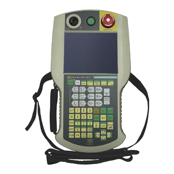
PRELIMINARY II 1.7.2010 Overview 1.3 Wireless Teach Pendant F IWLAN Wireless Teach Pendant F IWLAN Front view and side view ① Rotary switch ② EMERGENCY STOP button ③ Illuminated pushbutton ④ Display with touch screen ⑤ LED display ⑥ Carrying strap ⑦... - Page 15 ● Japanese ● English ● French ● Chinese ● Czech ● Russian The Wireless Teach Pendant F IWLAN works wirelessly on battery power, or it can be mounted in the docking station. Rear view ① Tray foot ② Nameplate ③...
-
Page 16: Main Rechargeable Battery
The set contains 10 protective foils. Order number: 6AV6645-7BF25-0TA0 ● Memory card Only use SD memory cards that have been tested and approved for used by Siemens AG for the Wireless Teach Pendant F IWLAN. Note The MicroMemory card of the SIMATIC S7 controller is not suited for use with this HMI device. -
Page 17: Equipment For Hmi Device And Plant
1.6.2 Docking station The docking station is used for secure storage of the Wireless Teach Pendant F IWLAN. When the Wirreless Teach Pendant F IWLAN rests in the docking station, the rechargeable batteries. i.e. main battery and backup battery, will be charged. -
Page 18: Charger
1.6.3 Charger° The charger is used to charge and store the main batteries for the Wireless Teach Pendant F IWLAN. You can charge one main battery in each of the two charger sections. NOTICE Chargers suited for office environments only If you use the charger in ambient conditions that do not correspond to an office environment, malfunctions may occur. -
Page 19: Power Supply Unit
120 and 230 V AC power networks. The setting of the voltage range takes place automatically. The output voltage is 24 VDC. ① "Power" LED ② Connecting cable ③ Power supply unit ④ Power supply cable Order number: 6AV6671-5CN00-0TA0 Wireless Teach Pendant F IWLAN V2 Operating Instructions, 08/2010, A5E02453837-01... -
Page 20: Rfid Tag
The RFID tag is required to log onto a machine. The RFID tag is a MDS D100 mobile data storage unit. Order number: 6GT2600-0AD10 The RFID tag includes the following accessories: ● Spacer Order number: 6GT2190-0AA00 ● Fixing pocket Order number: 6GT2190-0AB00 Wireless Teach Pendant F IWLAN V2 Operating Instructions, 08/2010, A5E02453837-01... -
Page 21: Access Point
W788-2RR 6GK5 788-2AA60-6AB0 SCALANCE Internal 6GK5 786-1BA60-2AA0 W786-1PRO 6GK5 786-1BA60-2AB0 SCALANCE Internal 6GK5 786-2BA60-6AA0 W786-2RR 6GK5 786-2BA60-6AB0 SCALANCE External 6GK5 786-2AA60-6AA0 W786-2RR 6GK5 786-2AA60-6AB0 US version Read the relevant documentation. Wireless Teach Pendant F IWLAN V2 Operating Instructions, 08/2010, A5E02453837-01... -
Page 22: Communication And Approved Controllers
Additional access points and WLAN products are available in the Internet at: Industry Mall (http://mall.automation.siemens.com) Communication and approved controllers Number of communication connections Communication link Wireless Teach Pendant F IWLAN V2 Quantity, max. Approved PLCs NOTICE Safety-related communication A non-fail-safe controller cannot ensure safety-related communication. -
Page 23: Supported Wincc Flexible Objects
Object Specification HMI device Number 2 048 Limit value monitoring Input/Output Linear scaling Input/Output Text list Number Graphics list Number The maximum total of text and graphics lists is 500. Wireless Teach Pendant F IWLAN V2 Operating Instructions, 08/2010, A5E02453837-01... - Page 24 Filing format CSV with ANSI character set Location Memory card USB stick Network drive The number of entries in the log may be restricted by the capacity of the storage medium. Wireless Teach Pendant F IWLAN V2 Operating Instructions, 08/2010, A5E02453837-01...
- Page 25 PROFINET IO direct keys Device-specific functions Object Specification HMI device Main rechargeable battery Showing the battery charge WLAN quality Displaying WLAN quality Effective range (RFID) name Display effective range name Wireless Teach Pendant F IWLAN V2 Operating Instructions, 08/2010, A5E02453837-01...
-
Page 26: Configuration And Process Control Phases
Process control phase The process control phase includes operation and monitoring of active production processes with the HMI device. The HMI screens on the HMI device visualize the production process. Wireless Teach Pendant F IWLAN V2 Operating Instructions, 08/2010, A5E02453837-01... -
Page 27: Areas In The Rfid Tag System
Overview 1.11 Areas in the RFID tag system The following figure shows an example configuration of a plant control system which is operated with a Wireless Teach Pendant F IWLAN. 1.11 Areas in the RFID tag system The following areas are available in a plant for fail-safe operation with RFID tag logon: ●... - Page 28 HMI device to log onto a machine. The RFID transmission and reception range of the HMI device is brought into the effective range of the RFID tag in order to log on. A signal lamp indicates whether an HMI device is logged onto a machine. Wireless Teach Pendant F IWLAN V2 Operating Instructions, 08/2010, A5E02453837-01...
-
Page 29: Rapid Roaming
This makes it possible to switch to another access point very quickly if it becomes necessary. Unlike iPCF, with iPCF-MC the handover times do not depend on the number of radio channels in use. Wireless Teach Pendant F IWLAN V2 Operating Instructions, 08/2010, A5E02453837-01... - Page 30 For rapid roaming with iPCF-MC, you will require a suitable access point – see section "Access point (Page 21)". We always recommend that you activate iPCF or iPCF-MC mode for PNIO communication. Wireless Teach Pendant F IWLAN V2 Operating Instructions, 08/2010, A5E02453837-01...
- Page 31 Make sure that a segment is available with a sufficiently powerful signal. Limitations due to iPCF-MC iPCF-MC is an in-house development of the Siemens AG that will only work with participants in which iPCF-MC has been installed. Operating principle of iPCF-MC iPCF-MC uses both radio interfaces of the access point differently: One interface works as management interface and sends a beacon every five milliseconds.
-
Page 32: Terms For Fail-Safe Operation
The HMI device revokes the operator authorization for the enabling button. The operator is prompted to confirm the "Forced logoff" dialog. ● Automatic logoff in the event of a communication error Wireless Teach Pendant F IWLAN V2 Operating Instructions, 08/2010, A5E02453837-01... - Page 33 A communication error occurs when the communication between HMI device and fail-safe controller is interrupted. Additional information is available in the section "Communication error for the integrated HMI device (Page 256)". Wireless Teach Pendant F IWLAN V2 Operating Instructions, 08/2010, A5E02453837-01...
- Page 34 PRELIMINARY II 1.7.2010 Overview 1.13 Terms for fail-safe operation Wireless Teach Pendant F IWLAN V2 Operating Instructions, 08/2010, A5E02453837-01...
-
Page 35: Safety Instructions And Standards
Commissioning of the HMI device is prohibited until it has been absolutely ensured that the machine to be operated with the HMI device complies with Directive 2006/42/EC. Verify before commissioning that the provisions of Directive 2006/42/EC are fulfilled. Wireless Teach Pendant F IWLAN V2 Operating Instructions, 08/2010, A5E02453837-01... -
Page 36: Approvals
● 1999/5/ECG "Directive of the European Parliament and of the Council from March 9, 1999 relating to Radio Equipment and Telecommunications Terminal Equipment and the Mutual Recognition of their Conformity" Wireless Teach Pendant F IWLAN V2 Operating Instructions, 08/2010, A5E02453837-01... - Page 37 AS/NZS 2064 (Class A). Wireless approval The national approvals for the HMI device are listed on the back of the device and in the product information for "Wireless Teach Pendant F IWLAN" in the Internet (http://support.automation.siemens.com/WW/view/en/30360848/133300). Requesting certificates...
-
Page 38: Standards On Operating Safety
EN 301489-3 Electromagnetic compatibility and radio spectrum 01.01.2003 matters (ERM) EN 301489-17 Electromagnetic compatibility and radio spectrum 01.07.2009 matters OET 65, RSS-210, Part 15247, 15407 radio authorization RFID 15225, RSS 210 Wireless Teach Pendant F IWLAN V2 Operating Instructions, 08/2010, A5E02453837-01... -
Page 39: Operating Conditions
● Taiwan – LP0002 Operating conditions The national approvals for the HMI device are listed on the back of the device and in the product information for "Wireless Teach Pendant F IWLAN V2" in the Internet (http://support.automation.siemens.com/WW/view/en/30360848/133300). NOTICE Wireless control device A wireless control device may cause interference. -
Page 40: Risk Analysis Of The Plant
Take the plant configuration as a whole into consideration in the risk analysis and not just the separate sections. For additional information on risk analysis and risk mitigation, refer to the "Safety Technology in SIMATIC S7" system manual (http://support.automation.siemens.com/WW/view/en/12490443). See also Safety-related operator controls (Page 88) Wireless Teach Pendant F IWLAN V2 Operating Instructions, 08/2010, A5E02453837-01... -
Page 41: Safety Functions Of The Emergency Stop Button
EMERGENCY STOP button must not cause a hazardous situation (see also EN 60204- 1, Section 9.2.5.3). The stop function is not to be used as a replacement for safety equipment. Wireless Teach Pendant F IWLAN V2 Operating Instructions, 08/2010, A5E02453837-01... -
Page 42: Safety Functions Of The Enabling Mechanism
Positions 1 and 3 of the enabling button are Off functions. Only the middle position allows the enabling function. EN 60204-1 is identical to IEC 60204-1, whereby the 3-stage enabling button is gaining international importance. Wireless Teach Pendant F IWLAN V2 Operating Instructions, 08/2010, A5E02453837-01... - Page 43 The enabling button only has an effect when the HMI device is logged onto a machine and the "RNG" LED on the HMI device is lit. See also Risk analysis of the plant (Page 40) Wireless Teach Pendant F IWLAN V2 Operating Instructions, 08/2010, A5E02453837-01...
-
Page 44: Electromagnetic Compatibility
"Lightning and overvoltage protection". Pulse-shaped disturbance Tested with Degree of severity Asymmetrical coupling 2 kV power cable DC voltage with protective elements Symmetrical coupling 1 kV power cable DC voltage with protective elements Wireless Teach Pendant F IWLAN V2 Operating Instructions, 08/2010, A5E02453837-01... - Page 45 < 47 dB (V/m) quasi-peak Note Before you connect the HMI device to the public electrical network, ensure that it is compliant with Limit Value Class B in accordance with EN 55022. Wireless Teach Pendant F IWLAN V2 Operating Instructions, 08/2010, A5E02453837-01...
-
Page 46: Transport And Storage Conditions
● Proper transportation and storage ● Proper installation and mounting ● Careful operation and maintenance The warranty for the HMI device will be deemed void if these stipulations are not heeded. Wireless Teach Pendant F IWLAN V2 Operating Instructions, 08/2010, A5E02453837-01... -
Page 47: Planning The Use
Planning the installation location and clearance of the clearance for the docking station. docking station (Page 56) Plan the location for the signal Planning the installation location of signal lamps lamps. (Page 57) Wireless Teach Pendant F IWLAN V2 Operating Instructions, 08/2010, A5E02453837-01... -
Page 48: 3.2 Operating Conditions
If you place the HMI device on a surface with a high natural frequency, malfunctions may occur as a result. Do not place the HMI device on a surface with a high natural frequency. Wireless Teach Pendant F IWLAN V2 Operating Instructions, 08/2010, A5E02453837-01... - Page 49 < 0.5 vpm, Test: 10 cm ; 10 days relative humidity < 60%, no condensation S < 0.1 vpm, Test: 1 cm ; 10 days relative humidity < 60%, no condensation Wireless Teach Pendant F IWLAN V2 Operating Instructions, 08/2010, A5E02453837-01...
-
Page 50: Insulation Resistance, Protection Class And Degree Of Protection
< 50 V 500 VDC Protection class of the HMI device HMI device Protection class according to IEC 60417-DB-HS Front and rear panel Protection class III Wireless Teach Pendant F IWLAN V2 Operating Instructions, 08/2010, A5E02453837-01... -
Page 51: Wlan Properties
Check your local wireless conditions prior to start-up. When planning the wireless channels, mode 802.11a is preferable. Ad hoc network An ad hoc network cannot be used in conjunction with the HMI device. Wireless Teach Pendant F IWLAN V2 Operating Instructions, 08/2010, A5E02453837-01... -
Page 52: Planning Protection Zones In The Rfid Tag System
However, operation in the fail-safe mode with the enabling button is then not possible. The following figure shows a plant with a protection zone. ① Protection zone limit ② Plant section in the protection zone ③ RFID tag with effective range Wireless Teach Pendant F IWLAN V2 Operating Instructions, 08/2010, A5E02453837-01... - Page 53 The security system can be controlled by a safety program, such as a program for robot control conforming to a robotics directive. See also Example of an application (Page 267) Wireless Teach Pendant F IWLAN V2 Operating Instructions, 08/2010, A5E02453837-01...
-
Page 54: Planning An Installation Location For Rfid Tags
The HMI device uses the RFID tag to log onto a machine within a protected area. Effective range of the RFID tag The radius of the effective range of an RFID tag is a maximum of 5 cm. Wireless Teach Pendant F IWLAN V2 Operating Instructions, 08/2010, A5E02453837-01... - Page 55 ● An RFID tag cannot be assigned to two machines. ● To log onto a machine, the distance between the HMI device and the RFID tag may not be more than 5 cm. Wireless Teach Pendant F IWLAN V2 Operating Instructions, 08/2010, A5E02453837-01...
-
Page 56: Planning The Installation Location And Clearance Of The Docking Station
● No exposure to direct sunlight ● It is easy to hook in and remove the HMI device in the docking station ● Ergonomic operation of the HMI device in the docking station is ensured Wireless Teach Pendant F IWLAN V2 Operating Instructions, 08/2010, A5E02453837-01... -
Page 57: Planning The Installation Location Of Signal Lamps
The signal lamp notifies the operator that he/she has logged on to the machine. Plan a clearly visible installation location for the signal lamp that is assigned to a machine. Wireless Teach Pendant F IWLAN V2 Operating Instructions, 08/2010, A5E02453837-01... -
Page 58: Coexistence Of The Frequency Bands
LAN systems and WirelessHART systems in the 2.4 GHz band. Avoid simultaneous use of overlapping frequency ranges. There is overlapping between Industrial Wireless LAN and WirelessHART – see "SCALANCE W-700" configuration manual (http://support.automation.siemens.com/WW/view/en/32816761), section 2.3. See also WLAN properties (Page 51) Wireless Teach Pendant F IWLAN V2 Operating Instructions, 08/2010, A5E02453837-01... -
Page 59: Planning Information Security
WLAN. In doing so, take into consideration: ● Configuration phase ● Process control phase Check the interplay of the specified measures. Wireless Teach Pendant F IWLAN V2 Operating Instructions, 08/2010, A5E02453837-01... - Page 60 "SCALANCE W-700" configuration Configure the access point so that the SSID of manual the radio cell remains hidden. (http://support.automation.siemens. com/WW/view/en/32816761) Change the SSID setting. Entering and deleting a password (Page 114) Wireless Teach Pendant F IWLAN V2 Operating Instructions, 08/2010, A5E02453837-01...
- Page 61 Enable encryption for data transmission in the Section "Configuring the WLAN WLAN configuration. connection (Page 116)" Change the default password for accessing the WLAN configuration in the Web Based management. Wireless Teach Pendant F IWLAN V2 Operating Instructions, 08/2010, A5E02453837-01...
- Page 62 ● System manual "Fundamentals - Industrial Wireless LAN", section "Information security of wireless communication in accordance with IEEE 802.11". ● Brochure "Wireless Communication Systems and their Security Aspects" published by the German Federal Agency for Security in Information Technology Wireless Teach Pendant F IWLAN V2 Operating Instructions, 08/2010, A5E02453837-01...
-
Page 63: Mounting And Connection
Do not use damaged parts If you use defective parts from the scope of delivery, you may experience malfunctions. If you find defective parts in the scope of delivery, contact your Siemens partner. Only install undamaged parts. Installing an RFID tag Requirement ●... -
Page 64: Installing The Docking Station
1. Place the docking station on the mounting surface. 2. Mark the fastening holes with a marking-off tool. 3. Drill two through holes or two threaded holes M5. 4. Mount the docking station. Wireless Teach Pendant F IWLAN V2 Operating Instructions, 08/2010, A5E02453837-01... -
Page 65: Connecting The Docking Station And Charger
1. Pull the plug of the 24 V power cable out of the socket of the docking station or out of the charger. 2. Disconnect the power supply unit from the mains. See also Power supply unit (Page 19) Wireless Teach Pendant F IWLAN V2 Operating Instructions, 08/2010, A5E02453837-01... -
Page 66: Connecting The Hmi Device
Do not open the connection or battery compartment if dust or moisture can enter the device. Close an open compartment completely. See also ESD guideline (Page 251) Wireless Teach Pendant F IWLAN V2 Operating Instructions, 08/2010, A5E02453837-01... -
Page 67: Opening And Closing The Terminal Compartment
When closing the connection compartment, ensure that: – The seal is present and properly positioned. – The connection cables of the rechargeable buffer battery are not pinched. 2. Tighten the screws. The connection compartment is open. Wireless Teach Pendant F IWLAN V2 Operating Instructions, 08/2010, A5E02453837-01... -
Page 68: Ports And Reset Button
The RJ45 interface is only suitable for commissioning. If you want to use the RJ45 port, the connection compartment must be open. The IP65 degree of protection is no longer met for the Wireless Teach Pendant F IWLAN when the connection compartment is open. -
Page 69: Inserting A Memory Card
An arrow on the memory card indicates the front side and the direction of insertion. When the memory card is correctly inserted into the slot, it stands approx. 3 mm proud of the slot. 3. Close the connection compartment or proceed with the following tasks. Wireless Teach Pendant F IWLAN V2 Operating Instructions, 08/2010, A5E02453837-01... - Page 70 Procedure – removing a memory card Proceed as follows: 1. Pull the memory card out of the slot. 2. Store the memory card in a safe place. 3. Close the connection compartment. Wireless Teach Pendant F IWLAN V2 Operating Instructions, 08/2010, A5E02453837-01...
-
Page 71: Connecting The Rechargeable Buffer Battery
2. Plug the connector if the cable into the socket on the printed circuit board. 3. Position the cable so that it is not pinched when you close the connection compartment. 4. Close the connection compartment. Wireless Teach Pendant F IWLAN V2 Operating Instructions, 08/2010, A5E02453837-01... -
Page 72: Replacing And Charging The Main Rechargeable Battery
Store unused rechargeable batteries away from the following items which can cause the contacts to be bridged. These include: – Paper clips – Coins – Keys – Nails – Screws or other small metal objects Wireless Teach Pendant F IWLAN V2 Operating Instructions, 08/2010, A5E02453837-01... -
Page 73: Replacing The Main Rechargeable Battery
The rechargeable battery is charged again in this state and then reaches 100 percent. Discharging to 80 percent and recharging to 100% adds up to a full charge cycle. Keep main rechargeable batteries in stock. Wireless Teach Pendant F IWLAN V2 Operating Instructions, 08/2010, A5E02453837-01... - Page 74 If you are using the HMI device for the first time, there is no main rechargeable battery in the battery compartment. 3. Remove the main rechargeable battery by pulling on the ribbon. 4. Insert a charged main rechargeable battery. 5. Close the compartment cover fully. Wireless Teach Pendant F IWLAN V2 Operating Instructions, 08/2010, A5E02453837-01...
-
Page 75: Charging The Main Rechargeable Battery
The "POWER" LED lights up. 4. Place the rechargeable battery into the charger. The rechargeable battery is fully charged once all five LEDs are lit. See section "Showing the battery charge (Page 76)". Wireless Teach Pendant F IWLAN V2 Operating Instructions, 08/2010, A5E02453837-01... -
Page 76: Showing The Battery Charge
If all the LEDs light up, the main rechargeable battery is fully charged. Note This applies to rechargeable batteries that are stored – read the section "Maintenance and care (Page 237)". Wireless Teach Pendant F IWLAN V2 Operating Instructions, 08/2010, A5E02453837-01... -
Page 77: Connecting The Plc
Connecting the PLC Only use approved components to connect a SIMATIC S7 PLC. You can find more information on this on the Internet in Industry Mall (http://mall.automation.siemens.com). Configuration graphic The following figure shows the connection between the PLC and the HMI device. -
Page 78: Connecting The Configuration Pc
● Connection via WLAN ● Connection via LAN and RJ45 interface ● Connection via USB Configuration graphic The following figure illustrates the options for connection between the HMI device and the configuration PC. Wireless Teach Pendant F IWLAN V2 Operating Instructions, 08/2010, A5E02453837-01... - Page 79 PC via the RJ45 port. Connect a configuration PC directly to the HMI device only as long as it is necessary. You can find additional information in the "Restoring factory settings (Page 194)" section. Wireless Teach Pendant F IWLAN V2 Operating Instructions, 08/2010, A5E02453837-01...
-
Page 80: Connecting A Usb Device
Devices without a separate power supply connected to the USB port increase the power load. This will reduce the service life of the HMI device. See also Specifications (Page 244) Wireless Teach Pendant F IWLAN V2 Operating Instructions, 08/2010, A5E02453837-01... -
Page 81: Switching On And Testing The Hmi Device
– No project is loaded on the device. – At least one data channel has been configured. The following dialog appears: 2. Press the "Cancel" button. The transfer is canceled. The Loader appears. Wireless Teach Pendant F IWLAN V2 Operating Instructions, 08/2010, A5E02453837-01... -
Page 82: Switching Off The Hmi Device
HMI device. Procedure Proceed as follows: 1. Press the "ON/OFF" button on the HMI device at least 4 seconds. The HMI device switches off. See also Switch-off behavior (Page 208) Wireless Teach Pendant F IWLAN V2 Operating Instructions, 08/2010, A5E02453837-01... -
Page 83: Operator Controls And Displays
The following figure shows the membrane keyboard of the Wireless Teach Pendant F IWLAN. ① Membrane keyboard – six buttons simultaneously enabled ② Membrane keyboard for robot control ③ Key "ON/OFF" Wireless Teach Pendant F IWLAN V2 Operating Instructions, 08/2010, A5E02453837-01... - Page 84 Outside of the project, the keys of the membrane keyboard have no function. Displays and other operator controls ● LED display ● EMERGENCY STOP button ● Enabling button ● Rotary switch ● Illuminated pushbutton Wireless Teach Pendant F IWLAN V2 Operating Instructions, 08/2010, A5E02453837-01...
-
Page 85: Led Display
The "RNG" LED is off when the HMI device is logged off a machine. Refer to the plant documentation for additional information on the meaning of the LEDs. Wireless Teach Pendant F IWLAN V2 Operating Instructions, 08/2010, A5E02453837-01... - Page 86 ● If the battery is not fully charged, the "BAT" LED signals according to column ● If the main rechargeable battery is fully charged, the "BAT" LED signals according to ③ column Wireless Teach Pendant F IWLAN V2 Operating Instructions, 08/2010, A5E02453837-01...
-
Page 87: Power Management
● "Power Save 2" corresponds to the "Switch off screen" setting. Note When the HMI device is logged on to a machine, "Power Save 2" operating mode is not available. Wireless Teach Pendant F IWLAN V2 Operating Instructions, 08/2010, A5E02453837-01... -
Page 88: Safety-Related Operator Controls
Annex K. You can find additional information in the section "Safety functions of the EMERGENCY STOP button (Page 41)". Due to its position, the EMERGENCY STOP button is equally accessible for both left-handed and right-handed persons. Wireless Teach Pendant F IWLAN V2 Operating Instructions, 08/2010, A5E02453837-01... - Page 89 Proceed as follows: 1. Press the EMERGENCY STOP button fully if a dangerous situation develops. The EMERGENCY STOP button engages in the EMERGENCY STOP position. The associated plant unit is stopped. Wireless Teach Pendant F IWLAN V2 Operating Instructions, 08/2010, A5E02453837-01...
-
Page 90: Enabling Button
HMI device. You can find additional information in the "Safety functions of the enabling mechanism (Page 42)" section. The enabling button is required to confirm axis movements, for example. Wireless Teach Pendant F IWLAN V2 Operating Instructions, 08/2010, A5E02453837-01... - Page 91 If you do not press the center of the enabling button, the enabling button may tilt. The switching process is delayed by this. A discrepancy error may occur – see section "Discrepancy error during enabling (Page 258)". Press the enabling button in the middle. Wireless Teach Pendant F IWLAN V2 Operating Instructions, 08/2010, A5E02453837-01...
-
Page 92: Testing The Function
Procedure Proceed as follows: 1. Switch on the HMI device. 2. Press both enabling buttons when the "Test Enabling Button" dialog is shown. 3. Press the EMERGENCY STOP button. Wireless Teach Pendant F IWLAN V2 Operating Instructions, 08/2010, A5E02453837-01... -
Page 93: Operator Controls
5.5.3 Evaluating operator controls 5.5.3.1 Overview The following information can be obtain between the Wireless Teach Pendant F IWLAN and PLC: ● Control state of the rotary switch ● Control state of the illuminated pushbutton ● Signal status of the LEDs There are two ways of transferring information: ●... -
Page 94: Evaluating Operator Controls As Direct Keys
Refer to your plant documentation for additional information. Bit assignment The following tables show the bit assignment for the rotary switch and illuminated pushbutton: ● Bit coding of rotary switch State Automatic mode Manual control Wireless Teach Pendant F IWLAN V2 Operating Instructions, 08/2010, A5E02453837-01... -
Page 95: Holding, Operating And Setting Down The Hmi Device
Read the section "Safety-related operator controls (Page 88)". The neck strap provides support for holding of the Wireless Teach Pendant F IWLAN. Use the velcro closure on the neck strap to attach the strap to HMI device and adjust the length as necessary. - Page 96 The HMI device can be used as a stationary device when it is placed in the docking station. The following figure shows how the HMI device is placed in the docking station. Wireless Teach Pendant F IWLAN V2 Operating Instructions, 08/2010, A5E02453837-01...
-
Page 97: Desktop And Loader
Once the HMI device is switched on and booted, the display shows the desktop with the Loader. ① Desktop ② Loader ③ Start menu ④ Icon for screen keyboard ⑤ Icon for displaying IP information about the WLAN/LAN connection Wireless Teach Pendant F IWLAN V2 Operating Instructions, 08/2010, A5E02453837-01... -
Page 98: Enabling And Disabling Securemode
Control Panel and the Windows CE taskbar. Backup password to protect it against loss. You can find additional information on updating the operating system in the section "Updating the operating system (Page 191)." Wireless Teach Pendant F IWLAN V2 Operating Instructions, 08/2010, A5E02453837-01... -
Page 99: Control Panel
Internet Explorer for Windows CE has separate proxy settings that are independent of the settings in the Control Panel of the HMI device. For more detailed information, refer to the Microsoft website. Wireless Teach Pendant F IWLAN V2 Operating Instructions, 08/2010, A5E02453837-01... -
Page 100: Operator Input Options
You can operate the Windows CE interface and Control Panel with an external mouse in the exact same way as you do with the touch screen of the HMI device. Wireless Teach Pendant F IWLAN V2 Operating Instructions, 08/2010, A5E02453837-01...